
ในกรณีส่วนใหญ่ มอเตอร์ไฟฟ้าไม่เสียหายเนื่องจากไฟฟ้าลัดวงจร โดยปกติแล้ว มอเตอร์จะหยุดทำงานเนื่องจากความร้อนสูงเกินไปจากการทำงานต่อเนื่องที่ 110% ของกระแสไฟฟ้าที่กำหนดเป็นเวลา 40 นาที เนื่องจากแบริ่งแห้งหรือการไหลถูกจำกัดผ่านปั๊มหรือข้อผิดพลาดอื่น ๆ ที่คล้ายกันซึ่งไม่ได้รับการตรวจพบจนฉนวนพันม้วนล้มเหลว อุปกรณ์เดียวที่สามารถตรวจจับความผิดปกติได้คือรีเลย์โอเวอร์โหลด ซึ่งเป็นส่วนป้องกันที่ถูกที่สุดของมอเตอร์สตาร์ทเตอร์.
ข้อมูลด้านล่างนี้อธิบายว่ารีเลย์โอเวอร์โหลดให้บริการอะไรในวงจรควบคุมมอเตอร์ วิธีการทำงานของรีเลย์แต่ละประเภท คลาสทริปที่ควรเลือก สาเหตุของการทริป และวิธีการตั้งค่ารีเลย์.
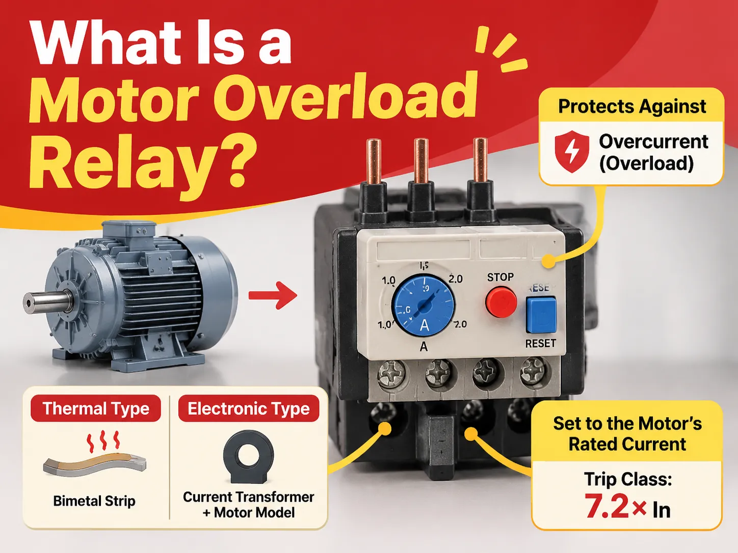
กล่าวโดยสรุป รีเลย์โอเวอร์โหลดมอเตอร์คืออุปกรณ์ในมอเตอร์สตาร์ทเตอร์ที่วัดกระแสไฟฟ้าและตัดวงจรควบคุมหากมอเตอร์ใช้กระแสไฟฟ้ามากเกินไปเป็นเวลานาน ดังนั้นอุปกรณ์นี้จึงไม่ให้การป้องกันไฟฟ้าลัดวงจร ซึ่งจะถูกจัดการโดยเบรกเกอร์ชนิดวงจรความร้อนใช้แถบไบเมทัลที่ถูกความร้อนจากกระแสไฟฟ้า ขณะที่ชนิดอิเล็กทรอนิกส์ใช้หม้อแปลงกระแสและแบบจำลองของมอเตอร์ การตั้งค่าคือกระแสไฟฟ้าที่กำหนดของมอเตอร์ ขณะที่คลาสทริปที่กำหนดไว้ที่ 7.2 เท่าของกระแสนี้ต้องพิจารณาเวลาการสตาร์ทของมอเตอร์.
สิ่งที่รีเลย์โอเวอร์โหลดทำในวงจรควบคุมมอเตอร์
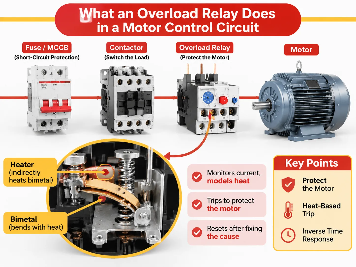
รีเลย์โอเวอร์โหลดไฟฟ้ามีบทบาทเฉพาะในควบคุมมอเตอร์ วัตถุประสงค์ของรีเลย์โอเวอร์โหลดในระบบคือปกป้องมอเตอร์จากการไหม้ของพันม้วน มากกว่าการปกป้องสายเคเบิลหรือคอนแทคเตอร์ ซึ่งเป็นสิ่งที่อธิบายได้มากในกระบวนการตั้งค่าเครื่องนี้.
ตัวป้องกันจะทำงานในสถานการณ์ที่แตกต่างกัน ดังนั้นอุปกรณ์แต่ละชิ้นจะรับผิดชอบต่อความล้มเหลวของตนเอง ประเภทแรกคืออุปกรณ์ป้องกันไฟฟ้าลัดวงจร เช่น ฟิวส์และเบรกเกอร์แบบเคสขึ้นรูปซึ่งสามารถรับมือกับกระแสไฟฟ้าลัดวงจรได้ถึงกิโลแอมป์ในเวลาเป็นมิลลิวินาที ประเภทที่สองคือคอนแทคเตอร์ที่ใช้แรงงานไฟฟ้าเมื่อสวิตช์โหลด รีเลย์โอเวอร์โหลดจะถูกใช้ระหว่างอุปกรณ์ทั้งสองเพื่อระบุเมื่อมอเตอร์ทำงานในสภาพที่พันมอเตอร์เสียหายและเครื่องยนต์ร้อนเกินไป.
ดังนั้นรีเลย์จึงทำงานตามฟังก์ชันหลักและไม่อนุญาตให้เครื่องยนต์ร้อนเกินไปหรือเสียหาย เมื่อพบความผิดปกติ รีเลย์จะเปิดคอนแทคเล็ก ๆ ซึ่งใช้ในวงจรคอนแทคเตอร์ หลังจากคอนแทคของคอนแทคเตอร์ถูกตัด มอเตอร์จะหยุดทำงาน แต่รีเลย์ต้องการการรีเซ็ตด้วยมือ.
ดังนั้นในความเป็นจริง รีเลย์จะปกป้องความจุความร้อนของมอเตอร์ เนื่องจากกระแสไฟฟ้าเป็นเพียงตัวบ่งชี้ทางอ้อม หากมอเตอร์ทำงานร้อน รีเลย์จะหยุดเครื่องยนต์ได้ยากกว่าหากอุปกรณ์ทำงานในโหมดเย็น เนื่องจากต้องพิจารณาความร้อนสะสมของมอเตอร์ก่อนการทำงาน.
การปฏิบัติแสดงให้เห็นว่าหากมอเตอร์มีการป้องกันที่เหมาะสม ไม่สำคัญว่ารีเลย์จะมีขนาดใหญ่แค่ไหน ปัญหาหลักของรีเลย์คือไม่ว่าจะทำงานหรือไม่ก็ตาม การเพิ่มความจุของรีเลย์ไม่ได้หมายความอะไรจนกว่าจะค้นพบสาเหตุหลักของปัญหา เวอร์ชันรวมของชุดประกอบทั้งหมด คอนแทคเตอร์บวกโอเวอร์โหลดบวกตัวครอบ เป็นสิ่งที่ มอเตอร์สตาร์ทเตอร์ประเภทนี้ บรรจุภัณฑ์ และการซื้อเป็นหน่วยเดียวช่วยลดความเสี่ยงของความไม่ตรงกันระหว่างคอนแทคเตอร์และรีเลย์ซึ่งเป็นสาเหตุของข้อผิดพลาดในการติดตั้งส่วนใหญ่.
วิธีการทำงานของ Motor Overload Relay แต่ละประเภท
ตลาดมีลักษณะโดยกลไกหลักสองประเภทและกลไกหนึ่งประเภทที่เพิ่งเกิดขึ้น.
- ประเภทแรกคือ Bimetal ซึ่งใช้การให้ความร้อนโดยอ้อม แต่ละเฟสผ่านองค์ประกอบที่ให้ความร้อนโดยส่วนประกอบไบเมทัลซึ่งประกอบด้วยโลหะสองชนิดที่ขยายตัวในอัตราที่แตกต่างกันทำให้มันโค้งงอเมื่อได้รับความร้อน เมื่อโค้งงอ มันจะทำงานกับแท่งสรุปและคันโยก ซึ่งปลดกลไกสแนปและเปิดคอนแทค 95-96 การให้ความร้อนโดยอ้อมหมายความว่า ฮีตเตอร์เป็นตัวรับผิดชอบในการให้ความร้อนแก่ไบเมทัล แตกต่างจากกระแสไฟฟ้าที่ส่งผ่านความร้อนผ่านไบเมทัล ข้อดีคือสามารถใช้เฟรมเดียวสำหรับระดับกระแสต่าง ๆ โดยการเปลี่ยนฮีตเตอร์ ผลลัพธ์ของการออกแบบนี้คือการบรรลุผลของเวลาผกผัน ที่กระแสที่กำหนดสองเท่า ไบเมทัลจะโค้งงอช้า ที่กระแสหกเท่า ไบเมทัลจะโค้งงอเร็ว ซึ่งสอดคล้องกับพฤติกรรมทางกายภาพของมอเตอร์ที่สามารถทนต่อกระแสสูงในเวลาสั้น ๆ และกระแสต่ำในโหมดเดินเบา มีไบเมทัลที่แตกต่างกันสำหรับวัตถุประสงค์การชดเชยซึ่งยกเลิกผลกระทบของอุณหภูมิแวดล้อม.
- ประเภทที่สองคือ Electronic หม้อแปลงกระแสตรวจสอบค่ากระแสของแต่ละเฟส และตามนั้นวงจรอิเล็กทรอนิกส์จะตัดสินใจตามแบบจำลองความร้อนและเปิดใช้งานรีเลย์ขนาดเล็กหรือทรานซิสเตอร์ที่สวิตช์วงจรเปิด ไม่มีฮีตเตอร์ในกระบวนการนี้ และ DVR สามารถสวิตช์กระแสต่าง ๆ ได้โดยการเปลี่ยนการตั้งค่า อุปกรณ์ไฟฟ้าเหล่านี้ใช้สำหรับการป้องกันมอเตอร์ รวมฟังก์ชันของอุปกรณ์ตัดวงจรลัดวงจรแม่เหล็กและโอเวอร์โหลดความร้อนในอุปกรณ์เดียวกัน.
ไม่ว่าจะใช้การป้องกันประเภทใด การเชื่อมต่อไฟฟ้าจะเหมือนกัน: ขั้ว 95-96 เป็นคอนแทคที่ปกติปิดสำหรับการตัดวงจรที่เชื่อมต่อแบบอนุกรมกับขดลวดคอนแทคเตอร์ ขั้ว 97-98 เป็นคอนแทคที่ปกติเปิดและใช้เป็นคอนแทคแสดงสถานะหรือส่งสัญญาณไปยัง PLC รีเลย์ที่เชื่อมต่อผ่านขั้ว 97-98 แทนขั้ว 95-96 จะไม่ตัดวงจร และข้อผิดพลาดนี้เกิดขึ้นบ่อยพอที่จะต้องตรวจสอบด้วยมิเตอร์ทุกครั้งที่ได้รับแผงวงจร ขดลวดของวงจรเดียวกันนี้ครอบคลุมใน ข้อกำหนดของ AC contactor, ซึ่งระบุแรงดันไฟฟ้าขดลวดที่วงจรควบคุมต้องตรงกัน.
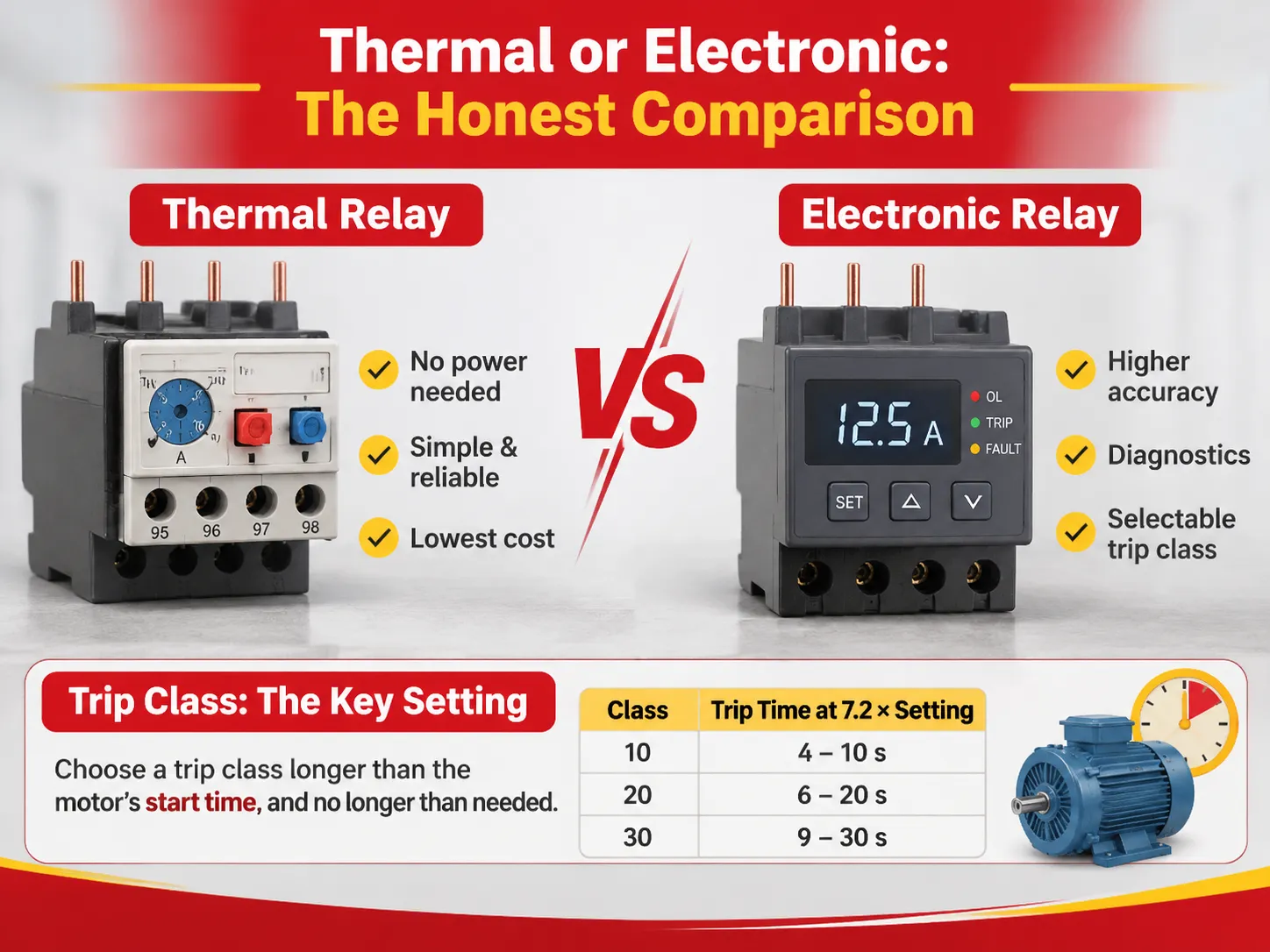
Thermal หรือ Electronic: การเปรียบเทียบอย่างตรงไปตรงมา
ทั้งสองเป็นคำตอบที่ถูกต้องสำหรับงานที่แตกต่างกัน และความแตกต่างของราคาน้อยกว่าความแตกต่างของฟีเจอร์.
| ปัจจัย | ความร้อน (ไบเมทัล) | อิเล็กทรอนิกส์ |
|---|---|---|
| ความแม่นยำ | ±10% ถึง 20% รอบการตั้งค่า | โดยทั่วไป ±5% หรือดีกว่า |
| การชดเชยสภาพแวดล้อม | −20 ถึง +60 °C บนโครงส่วนใหญ่ | −25 ถึง +60 °C กว้างขึ้นในบางรุ่น |
| คลาสทริป | กำหนดค่าคงที่เมื่อซื้อ โดยปกติเป็น Class 10 | เลือกได้ มักเป็น 5E ถึง 30E |
| หน่วยความจำความร้อน | โดยการระบายความร้อนทางกายภาพ ซึ่งเป็นไปได้จริง | ตามรุ่นและสถานะที่จัดเก็บ |
| การวินิจฉัย | ทริปหรือไม่ทริป | กระแสต่อเฟส โหลดความร้อน สาเหตุการทริป |
| ราคา | ต่ำสุด | สองถึงห้าครั้งของความร้อน ลดลง |
| เหมาะสำหรับ | ปั๊มมาตรฐาน พัดลม สตาร์ทเตอร์ง่าย | ไดรฟ์สำคัญ โหลดความเฉื่อยสูง โรงงานที่เชื่อมต่อเครือข่าย |
ข้อเสียของรีเลย์ความร้อนคือใช้ไบเมทัลที่ทำงานในลักษณะเดียวกับมอเตอร์แต่ไม่ใช่ในลักษณะที่ขจัดข้อจำกัดของมัน รีเลย์ความร้อนไม่แสดงสาเหตุของการทริปและได้รับผลกระทบจากอุณหภูมิในแผง นอกจากนี้ ความแม่นยำของรีเลย์ความร้อนยังได้รับผลกระทบจากปัจจัยอื่น เช่น ความคลาดเคลื่อนของฮีตเตอร์.
ข้อเสียของรีเลย์อิเล็กทรอนิกส์คือการพึ่งพาการตั้งค่าที่ถูกต้องและแหล่งจ่ายไฟ หากมีปัญหากับเอาต์พุต จะไม่มีสัญญาณส่งออก อย่างไรก็ตาม มีข้อดีเนื่องจากค่าที่อ่านได้จากรีเลย์อิเล็กทรอนิกส์สามารถนำไปใช้โดยทีมบำรุงรักษาสำหรับการใช้งานอื่น ๆ พฤติกรรมของด้านคอนแทคเตอร์ภายใต้ภาระงานเดียวกันถูกกำหนดไว้ในนี้ แนวทางการเลือกและการเดินสายคอนแทคเตอร์ AC, เพราะรีเลย์จะปกป้องมอเตอร์ได้ก็ต่อเมื่อคอนแทคเตอร์ยังทำงานได้เพียงพอที่จะตัดวงจร.
คลาสทริป: การตั้งค่าที่ทำให้เกิดการทริปรบกวนมากที่สุด
ตามมาตรฐาน IEC 60947-4-1 คลาสทริปหมายถึงเวลาที่ใช้ในการทริปที่ 7.2 เท่าของกระแสที่ตั้งไว้เมื่อมอเตอร์เย็น ถูกพัฒนาขึ้นเพื่อให้มอเตอร์ผ่านกระบวนการสตาร์ทโดยไม่ตรวจจับกระแสจนกว่ามอเตอร์จะหยุดทำงานอย่างสมบูรณ์.
| คลาส | เวลาในการทริปที่ 7.2 × การตั้งค่า จากสถานะเย็น | โหลดทั่วไป |
|---|---|---|
| 10A | 2 ถึง 10 วินาที | สตาร์ทเร็ว ความเฉื่อยต่ำ ระบบทำความเย็นแบบปิดสนิท |
| 10 | 4 ถึง 10 วินาที | Pumps, fans, small conveyors, general duty |
| 20 | 6 to 20 s | Loaded conveyors, compressors, larger fans |
| 30 | 9 to 30 s | Crushers, mills, centrifuges, high-inertia loads |
The demand for usage of tolerance band E in electronic relays is that the minimum rates for the classes are lower than for others, 3 seconds for 5E, 5 seconds for 10E, 10 seconds for 20E, and 20 seconds for 30E with the upper rates being equal to the one for other classes.
In order to decide on the proper trip class, the initial requirements can be put simply: it should be longer than the leading time of the motor. Still, despite the simplicity of the described rule, there is a risk of making a mistake while selecting a relay. When using Class 10 relay with a motor taking 14 seconds to reach working speed, it will trip at every attempt, so the temptation will be to adjust the setting current instead of changing the class of the relay, which will allow fixing the problem but deprive the motor of protection.
The people often make mistakes when calculating the possible current in case of using the star-delta starter. The current flowing through the overload relay installed on the main contactor is equal to 0.58 of the nominal current of the motor. If there is an additional overload relay protecting the motor during the star phase, it will be set to work at one third of the current value.
What Causes an Overload Relay to Trip, and What Does Not
The list of real causes is small compared to the long list of alleged causes associated with overloads.
A motor overload takes place when the effective current exceeds the rating for long enough to exceed the thermal limit. There are four major causes of overloads: mechanical issues, like a stuck bearing, or the impeller being blocked or misaligned; supply problems, such as low voltage, where the current increases; usage changes, such as the workpiece being heavier, or the damper being shut; and a failed start, where the motor does not change its speed and remains in the blocked current mode.
However, one must note some mistakes people make in their overload interpretations. Some of them are: a short circuit related to the breaker; a ground fault, requiring protection by the RCD; burnt-out main contacts of a contactor leading to an open circuit; and a fault in the control circuit manifesting in a failure of the latch-up. The last one is the most common misinterpretation since it produces the very same symptom: complete stoppage of the motor, which has to be restarted. A contactor that has lost a phase through contact erosion will draw more current on the remaining phases and will look exactly like an overload until someone inspects it, and the symptoms of that failure are set out in this look at อาการล้มเหลวของคอนแทคเตอร์ AC.
Repeating trips on a motor used for years is a mechanical, not a signal issue. Repeating trips on a new installation is most likely a setting or class fault. Any trips occurring only during the summer are likely to be temperature related. Any trips upon starting are likely to be a class fault or a star-delta setting fault. The fastest way to classify a trip is by its timing.
Setting the Dial: Rated Current, Not Tripping Current
The dial is calibrated according to the motor’s full-load current rating written on the nameplate and not to a value that prevents it from tripping. The standard IEC 60947-4-1 specifies that the relay should not trip under conditions where the current exceeds this value by a factor of 1.05, and it must trip within 2 hours where the current exceeds it by a factor of 1.2. The value on the dial becomes the starting point for the drawing of the inverse-time characteristics for the relay.
The typical range of the settings is 1.5:1, for instance 7.5-11 Amperes, and should ensure that the motor works within the specified range instead of at the extreme values to allow for small readjustments afterwards. In situations when the motor’s service factor exceeds 1.0, it would be reasonable to set it slightly higher than that specified in the nameplate information. If the service factor is equal to 1.0, then it should be set according to the nameplate data or slightly below this figure.
Once the commissioning is complete, the following three steps should be adhered to. The running current of the completed set-up should be measured and compared with that of the nameplate. The setting itself must be recorded on the panel schedule. The last step would be to choose the mode of change, manual or automatic, depending on whether a person will observe the equipment or not.
Where Phase Loss Changes Everything
Single phasing may create the most hazardous overload condition that a three-phase motor will have to face. When one phase has failed and the motor continues to run on two phases, the current flowing through the remaining windings rises sharply and takes up some of the bimetallic relay’s current load. A plain three-bimetal relay could be slow enough to allow for a first profession of winding failure.
The phase-loss-sensitive construction, sometimes referred to as differential, will incorporate a second summing bar that senses the difference in deflection between phases. An unbalanced-represented or missing phase will trip the relay faster than a symmetric overload with the same magnitude. The published figures bring the effect down to earth. On one common relay family, the ultimate trip current is 120% of full load, and with phase loss, it is 115%. Modern IEC relays are phase-loss-sensitive by default; older stock and cheap imports are often, and the data sheet does not always say so in plain English.
Choosing a Relay by Application
Five common situations and what to specify for each.
| การใช้งาน | Specification that matters | Suggested type |
|---|---|---|
| Pump or fan, direct on line | Class 10, phase-loss sensitivity, manual reset | Thermal relay, mounted on the contactor |
| Loaded conveyor or compressor | Class 20, thermal memory, remote reset | Electronic relay with selectable class |
| Crusher, mill, centrifuge | Class 30, stalled-rotor detection, current per phase | Electronic relay with communications |
| Star-delta starter | Setting at 0.58 times rated current, second relay in star | Thermal, sized to the main contactor |
| Single motor, small rating | Combined magnetic and thermal, one device | เบรกเกอร์ป้องกันวงจรมอเตอร์ |
In cases where a facility manufactures its own starters instead of purchasing it, the relay forms part of a triad of elements needed to make the decision. The coordination between the relay and the contactor has to take place so that the starter is not harmed as a result of fault clearing; this is indeed the essence of the meaning of type 2 coordination, and the degree of success in achieving this is entirely down to the selection of the upstream device.A 63 A frame miniature circuit breaker is the usual upstream choice on small starters, and its curve has to match the motor’s starting current or the first start will clear the breaker instead of the relay.
คำถามที่พบบ่อย
What is the function of an overload relay in a motor circuit?
In order to safeguard the motor winding from prolonged overcurrent, the method consists of opening the control circuit once the duration of the current is sufficient enough to surpass the thermal ability of the motor. It does not eliminate short circuits and cannot replace the breaker or fuse ahead of the control circuit.
What is the purpose of a thermal overload relay in a motor starter?
This protection mechanism operates using bimetal strips that are heated using the motor current. Its advantage in a starting switch is that it does not require any additional power source and behaves like the motor in temperature and current characteristics. Thus, this type of protection remains the standard for simple direct-on-line starters.
How does a motor overload relay work?
The heat produced by the current in a bimetal or a current transformer is compared with a thermal model. However, should the resulting signal exceed the limit according to the trip class, a normally-closed contact opens and the contactor drops. The contactor remains latched until reseting.
What is a type of overload relay used in a motor starter?
Four types of relays are generally used in practical applications. These are the thermal bimetal relay, electronic overload relay, motor protection circuit breaker which combines the properties of both thermal and magnetic relays, and the solid-state overload block which uses electronic methods to measure overload but has the same dimensions as thermally actuated relays.
What causes an overload relay to trip?
The occurrence of mechanical overload, low voltage supply, changes in the operational load, or a motor that fully fails to attain speed. In an older installation, a potential mechanical problem will show signs of multiple trips; however, a new installation could simply indicate the need for a different trip class or the wrong trip setting.
Does an overload relay protect against short circuit?
No, it is purposely made slow so that it can be able to pass through the starting of motors. Hence, it does not work for fault current. Hence, separate protection has to be provided against short circuit failures. These two devices have to be chosen together, so that starter survives the failure without being damaged.
Can I set the overload relay above the motor’s rated current?
The service factor can only be set higher if there is a valid reason for that. Putting the service factor higher to avoid nuisance trips defeats the purpose of having the motor in the first place, and instead of a trip, the next failure will be a winding.
อ้างอิง
- Siemens — SIRIUS Overload Relay Technical Documentation
- ABB — Thermal and Electronic Overload Relays
- Newark — Overload Relay and Motor Protection Components
- Grainger — Motor Controls and Overload Relays
- NEMA — Motor Control Equipment Standards
สรุป
An overload relay is slow at its work, guarding the appliance energetically. The essence of its task is to detect slight prolonged overcurrent, which implies setting its dial at motor rated current, the trip class just over the start time, and understanding that a trip is information only.
The only defects to watch for are a relay set too high and a relay 95-96 contact not connected to the coil circuit. In both cases, a motor is still unprotected even with a seemingly fully assembled panel, and checking for both cases doesn’t take more than a minute.