Ticari binanızda elektrik muayenesi yapmak üzere bir kişi gelir. Mühendis, toprak elektrodunun 22 Ohm olarak test edildiğini bildirir. Yakındaki biri, NEC 25 Ohm’a izin verdiği için her şeyin yolunda olduğunu söyler. Ancak ekipman üreticisinin el kitabı, hassas elektroniklerle çalıştığı için maksimum 5 Ohm gerektiğini belirtir; bu nedenle devreye alma mühendisi sizin için yeni olan bir spesifikasyona atıfta bulunur. Hangi değere uyulmalıdır? Sorulan soru, ticari elektrik alanında çalışanlar için çok yaygındır, ancak cevap ölçtüğünüz standarda bağlıdır.
Bu yazı, doğru olan kesin sayılarla cevabı hemen gösterir – hayali sayılar kullanılmayacaktır. NEC’in tam olarak ne istediğini, IEEE’nin ne dediğini, “25 Ohm kuralının nasıl çalıştığını” ve neyin güvenli kabul edildiğini öğreneceksiniz.
Hızlı bir cevap arıyorsanız, tüm ticari binalarda topraklama için maksimum direnç konusunda evrensel olarak geçerli net bir sayı yoktur çünkü bu cevap hangi standarda ve sistemin hangi bölümüne atıfta bulunduğunuza bağlıdır. NEC (NFPA 70) bir bina için genel maksimum direnç belirlemez, ancak 25 ohm kombinasyonu (aslında 250.53“te belirtilmiştir) sadece topraklama çubuğu veya plakası için pratik anlam taşır ve sadece 1 çubuk veya plakanın topraklama elektrodu için yeterli olup olmadığını görmek için kullanılır (yani, 1 elektrodun 25 ohm veya altında olması durumunda ikinci elektrodun kullanılmaması uygundur). Büyük ticari ve endüstriyel sistemler için IEEE’nin Std 142 (”Green Book”), birincil topraklama elektrodunun toprağa direncinin 1-5 ohm aralığında olması gerektiğini belirtir ve sektör uygulaması (NFPA/IEEE önerileri, NETA ATS uygulamaları, telekom endüstri standartları vb.) ticari binalar için yaklaşık 5 ohm ve hatta trafo merkezleri ve üretim tesisleri için 1 ohm hedeflemektedir. Özetle, NEC’in minimum gereksinimleri, ticari binalar için 1-5 ohm aralığında IEEE tarafından talep edilen performansla ilgili değildir; bu aralık sektörde yaygın olarak kabul edilen hedef değerdir ve 25 ohm üzeri ticari topraklama elektrodu için zayıf ve kabul edilemez olarak görülür.
Doğru olalım, çünkü yanlış bilginin kaynağı burasıdır. İlgili sayılar ve kaynakları:
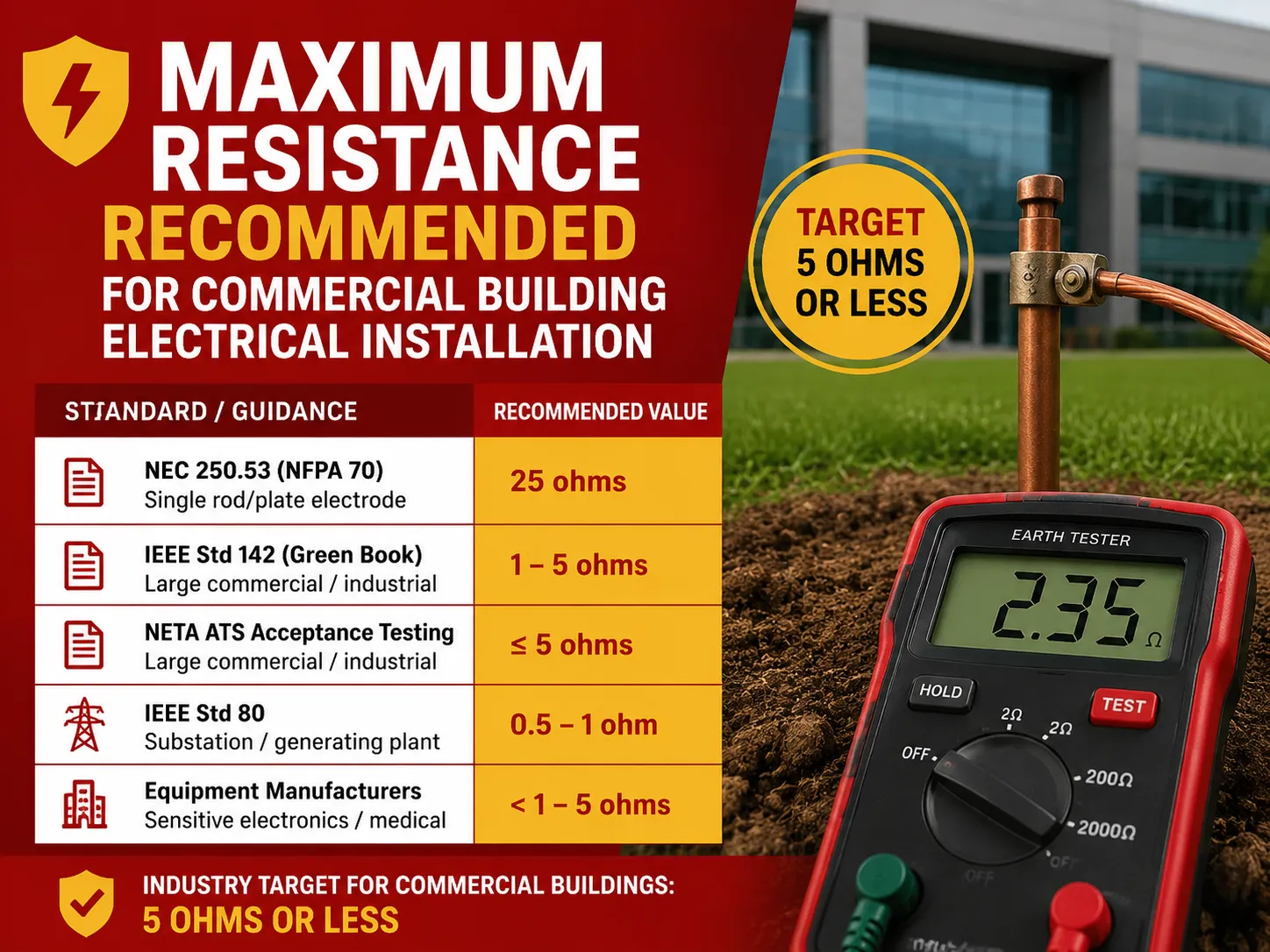
| Standart / Rehberlik | Değer | Uygulandığı Alan |
|---|---|---|
| NEC 250.53 (NFPA 70) | 25 ohm | Tek çubuk/plaka elektrod — direnç testi 25Ω veya daha az ise ikinci elektrod gerekmez |
| NEC 250.53 varsayılan | İki elektrod | Çubuk/boru/plaka elektrodlar varsayılan olarak iki adet; her ikisi takıldığında 25Ω testi gerekmez |
| IEEE Std 142 (Yeşil Kitap) | 1–5 ohm | Büyük ticari/endüstriyel sistemler için ana topraklama elektrodunun önerilen toprak direnci |
| IEEE Std 80 | 5–1 ohm | Trafo merkezi / üretim tesisi topraklama şebekeleri |
| NFPA/IEEE sektör rehberi | 5 ohm veya daha az | Yaygın olarak belirtilen ticari hedef; telekom endüstri standardı |
| NETA ATS kabul testi | 5 ohm / 1 ohm | ≤5Ω büyük ticari/endüstriyel; ≤1Ω üretim/iletim istasyonları |
| Ekipman üreticileri | <1 ila 5 ohm | Hassas elektronik / tıbbi tanı ekipmanı spesifikasyonları |
Önemli gerçek: NEC’de ticari bir topraklama için “25 ohm veya daha az” olma zorunluluğu yoktur. 25 sayısı yalnızca tek bir elektrottan yeterli mesafe olup olmadığını belirlemek için dahil edilmiştir. IEEE 142 ve NETA önerileri ve uygulamaları gibi performans gereksinimleri 1 ile 5 ohm arasında bir değer önermektedir – en yaygın kullanılan sınır ise 5 ohmdur.
NEC 25-Ohm Kuralı — Gerçek Anlamı
NEC Bölüm 250.53(A)(2) (ve ayrıca 2005 NEC Bölüm 250-56) uyarınca, kod iki topraklama elektrodu kurulmasını gerektirir. Ancak, tek bir elektrodun 25 ohm veya daha az toprak direncini sağladığı durumlarda izin verildiğine dair önemli bir istisna vardır. Ne yazık ki, bu genellikle sadece bir elektrodun kurulup direncinin test edilmesi ve eğer ilk elektrod 25 ohm direncini karşılamazsa ikinci elektrodun eklenmesi gerektiği şeklinde yanlış yorumlanmaktadır.
Aslında, dağılım şu şekildedir:
- Varsayılan = en az 6 feet arayla iki elektrodun kurulması.
- İzin verilen = toprak direncinin 25Ω veya daha az olduğunu doğrulayan uygun bir direnç testine tabi tutulan tek elektrod.
İkinci elektrodun kurulması durumunda, kombinasyonun 25 ohm koşulunu karşılaması gerekmez — çünkü ikinci elektrod kurulumuyla NEC gereksinimlerini yerine getirmiş sayılır.
IEEE 142 (Yeşil Kitap): 1–5 Ohm Önerisi
“Ticari bir yapı için önerilen direnç nedir?” sorusu, IEEE Std 142 olarak bilinen Yeşil Kitap’tan otoriter bir mühendislik çözümü alır. Önerilen değer, büyük endüstriyel ve ticari sistemlerde ana topraklama elektrodu için 1 ila 5 ohm arası toprak direncidir.
Bu direnç değerinin 25 ohma tercih edilmesinin nedeni, ticari tesislerin genellikle hassas elektroniklerle donatılmış olması ve bu nedenle sadece kod minimumuyla sağlanamayan çok stabil ve düşük empedanslı bir toprak referansına ihtiyaç duymasıdır. Yukarıda belirtilen düşük toprak direnci şunları sağlar:
- Arızadan kaynaklanan yüksek akımın kaynağa daha hızlı dönmesi
- Arıza sırasında ekipman kasasında daha az voltaj artışı
- Daha iyi yıldırım dalga sönümlenmesi
- Daha az elektriksel gürültü
Özetle, kod 25 ohm gerektirir; mühendislik terimleriyle iyi performans için gereken değer 1-5 ohmdur.
Sektör Uygulaması: Ticari Hedef Olarak 5 Ohm
Sahada, çoğu kişinin ticari sistemler için duyacağı bilgi “5 ohm veya daha az”dır. Bu, aşağıdaki çeşitli ancak tamamlayıcı kaynaklardan gelir:
- NFPA ve IEEE’nin 5.0 ohm veya daha azı iyi bir hedef olarak önerileri
- Telekomünikasyondaki yaklaşımlar (topraklama ve bağlama için 5 ohm veya daha az)
- NETA’nın kabul testleri standartları (ticari/endüstriyel sistemler için ≤5 ohm; enerji santralleri/iletim istasyonları için ≤1 ohm)
- farklı ekipman üreticileri tarafından verilen rakamlar (hassas elektronikler için 1 ila 5 ohm arasında)
Farklı mühendisler ve test uzmanlarının ortak tavsiyesine göre, ticari binalar için 5 ohm veya daha az iyidir, alt istasyonlar için ise ortalama değer 1 ohm ve altıdır. Bu NEC tarafından bir gereklilik değildir, ancak birçok tasarımcının takip ettiği ve testlere tabi olan en iyi uygulamalardır.
Güvenli Bir Aralık Var Mı? Sayıları Anlamak
Toprak direnç ölçümlerini pratikte nasıl yorumlayacağınız aşağıda açıklanmıştır:
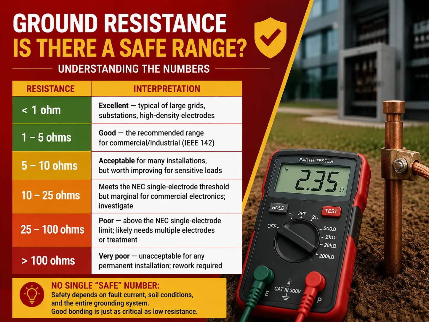
| Direnç | Yorumlama |
|---|---|
| < 1 ohm | Mükemmel — büyük şebekeler, trafo merkezleri, yüksek yoğunluklu elektrotlar için tipik |
| 1–5 ohm | İyi — ticari/endüstriyel için önerilen aralık (IEEE 142) |
| 5–10 ohm | Birçok kurulum için kabul edilebilir, ancak hassas yükler için iyileştirilmesi önerilir |
| 10–25 ohm | NEC tek elektrot eşik değerini karşılar ancak ticari elektronik için sınırda; inceleme yapılmalı |
| 25–100 ohm | Kötü — NEC tek elektrot sınırının üzerinde; muhtemelen birden fazla elektrot veya işlem gerektirir |
| > 100 ohm | Çok kötü — herhangi bir kalıcı kurulum için kabul edilemez; yeniden çalışma gereklidir |
Ana uyarı şudur: güvenlik açısından her durum için geçerli tek bir “güvenli” değer yoktur — bu, toprak hata akımı, toprak koşulları ve gerçek devre gibi farklı faktörlerden de etkilenir. Elektrot topraklama direncinin kalitesi sorunun sadece bir parçasıdır; tüm topraklama sisteminin bütünlüğü de aynı derecede önemlidir. 2 Ohm mükemmel bir elektrot, cihazların toprak iletkenleri eğri veya korozyona uğramışsa işe yaramaz.
20 Ohm Kötü mü? Ölçümünüzü Yorumlama
20 ohm direnç seviyeleri ticari bina inşaat kodunda olumlu görülmez, ancak bu değerle ilgili herhangi bir kod ihlali de yoktur, dolayısıyla:
- NEC standardı: Bu seviye yukarıdaki mevzuat tarafından belirlenen maksimum tek elektrot değerinden düşüktür. Yine de, 20 ohm direnç seviyesi, topraktaki nem seviyesinin mevsimsel artış ve azalışına bağlı olarak standartları aşmaya yakındır.
- IEEE 142 standardı: Bu standarda göre, 20 ohm direnç seviyesi önerilen 1-5 ohm değerini aşar, bu da aşırı gerilim koruması gibi bazı elektronik ekipmanların uygunsuz topraklama seviyesi nedeniyle zarar görebileceği anlamına gelir.
Pratikte, herhangi bir ticari kuruluş topraklamanın belirlenen standartlara uygun olmasını sağlar.
Sonuç: Genel olarak, 20 ohm direnç binanın güvenliğini tehdit etmeyebilir, ancak ticari bir bina için hala çok yüksektir; bu nedenle iyileştirilmesi gerekir.
Diğer Ticari Gereksinimler: Prizler ve Bağlantı
Toprak direnci ticari elektrik güvenliğinin bir parçasıdır. Ulusal Elektrik Kodu (NEC) gereksinimleri aşağıdaki gibidir:
- Ticari prizlerin özellikleri (NEC 406, 210.52, 210.8): Ticari prizler 125V, 15A ve/veya 20A tipinde belirtilmelidir, belirli yerlerde (banyolar, çatı katları, mutfaklar, dış mekanlar vb. 210.8(B) uyarınca) GFCI koruması sağlanmalıdır, tüm prizler metal kutuya bağlanacak ve her priz topraklama iletkenine bağlanmış olmalıdır.
- Bağlama işlemi (NEC 250.102-250.104): Borulama, çerçeveli ekipman, yapısal çelik, pompalama ekipmanı gibi enerjilenebilecek tüm metalik parçaların topraklama sistemine bağlanması gerektiğini anlamak esastır. Bağlama sürekliliği testi, elektrot direncinden ayrı olarak yapılacaktır (ekipman topraklama sistemine bağlıyken nokta-nokta direnç 0,5 ohm’u aşmamalıdır).
- Topraklama elektrot iletkeni (NEC 250.66): Topraklama elektrotları, servis maksimum çapını aşmayacak şekilde boyutlandırılmalı ve topraklama sistemini servis ekipmanına bağlamalıdır.
Devredeki koruyucu cihazları da doğruluyorsanız, açıklamamız devre kesiciler ile toprak kaçak devre kesicileri arasındaki farkları ticari panoda hangi korumanın ne yaptığını netleştirir.
Yüksek Elektrik Direnci Nedir?
Bağlam, “yüksek direnç” ifadesinin anlamında rol oynar:
- Topraklama elektrotları ölçülürken, yaklaşık 25 ohm’dan büyük olması anlamına gelir (örneğin, 100 ohm veya daha yüksek çok yüksek bir değerdir). “İdeal” direnç seviyesi 1-5 ohm’dur.
- Topraklama sürekliliği açısından, 0,5 ohm’dan fazla herhangi bir değer arıza olduğunu gösterir. Ekipman ile toprak arasındaki bağlantı neredeyse sıfır olmalıdır.
- İzolasyon direnci açısından, yüksek direnç değeri iyi bir direnç anlamına gelir çünkü mega ve gigaohm cinsinden ölçülür; 1 MΩ altındaki değerler arıza olasılığının yüksek olduğunu gösterir.
Sonuç olarak, “yüksek direnç” neredeyse her zaman bir sorun anlamına gelir (topraklama için) ancak iyi bir durumu da ifade edebilir (izolasyon için). “Yüksek direnç” terimi kullanılırken tam olarak ne kastedildiğinden emin olunmalıdır.
Toprak Direncini Etkileyen Faktörler
Toprak direnci sabit bir değer değildir. Koşullara göre değişir:
- Toprak direnç katsayısı: Kil/çamur (10–100 Ω·m) kum/çakıldan (1.000–10.000 Ω·m) daha düşük direnç katsayısına sahiptir.
- Nem içeriği: Islak topraklar daha düşük direnç gösterirken kuru hava direnci önemli ölçüde artırır.
- Sıcaklık: Soğuk toprak çok daha yüksek direnç gösterir.
- Elektrot derinliği ve kesit alanı: Daha uzun elektrotlar ve daha büyük plakalar toprağa daha derin iner.
- Elektrot sayısı ve aralığı: Elektrot sayısı arttıkça ve aralarındaki mesafe büyüdükçe direnç azalır.
- Elektrot malzemesi ve korozyon: Elektrotlar toprakta ne kadar uzun kalırsa korozyon o kadar artar ve direnç yükselir.
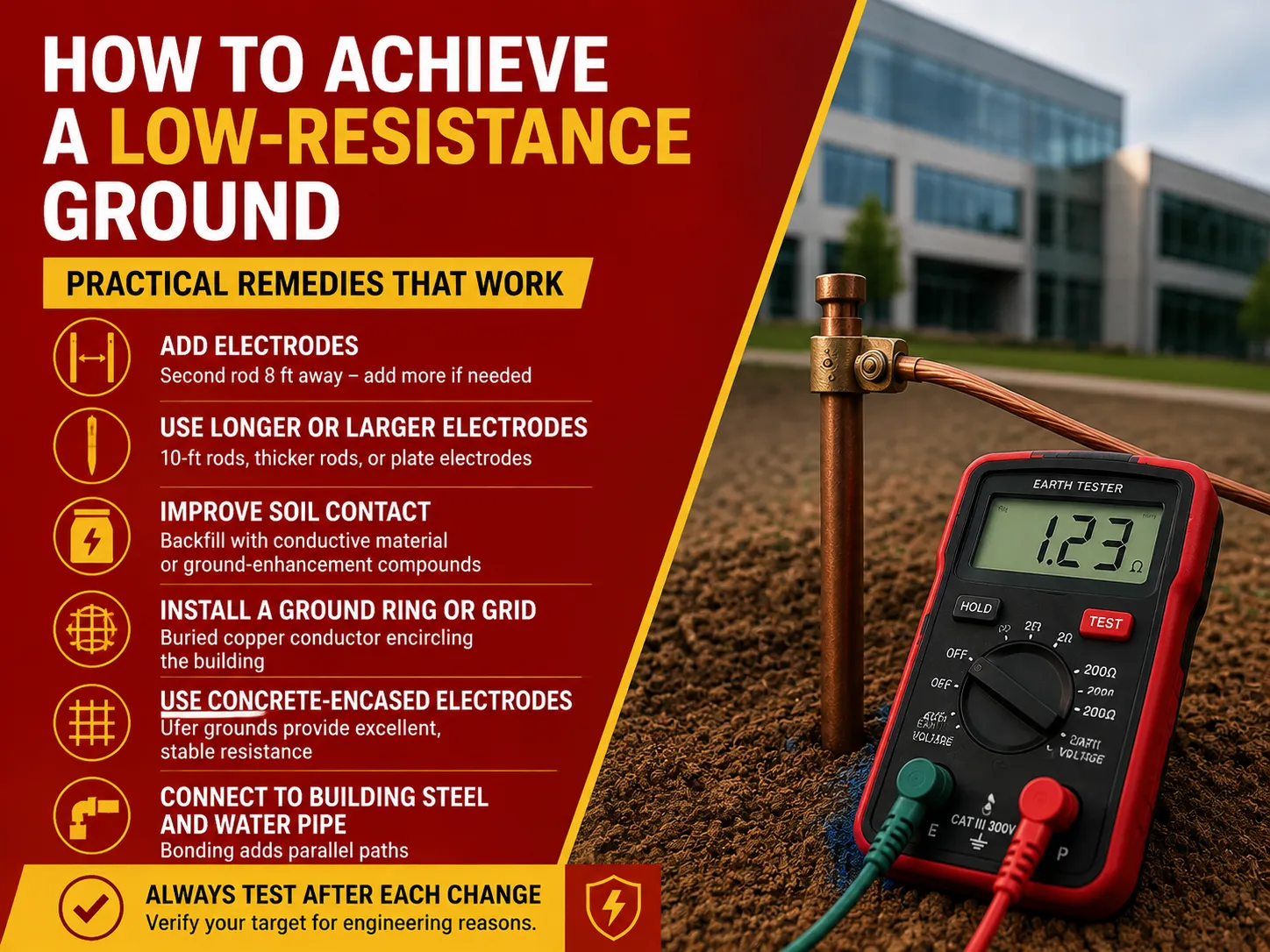
Düşük Dirençli Topraklama Nasıl Sağlanır
Ticari topraklamanız aşırı yüksekse, işte en maliyet-etkin çözümlerin sıralı listesi:
- Çubuk ekleyin: İlk çubuktan 8 feet uzaklıkta ikinci bir topraklama çubuğu eklemek direnci büyük ölçüde azaltır. Doğru direnç sağlanana kadar ek çubuklar eklemeye devam edin (eklenen her çubukla sağlanan fayda azalır).
- Daha büyük veya uzun çubuklar kullanın: Daha uzun (10 feet) veya kalın çubuklar ya da plaka elektrotlar kullanmak, daha derin ve daha az dirençli topraklara ulaşmaya yardımcı olur.
- Toprak bağlantısını iyileştirin: Çubuğun etrafına iletken malzemeler veya kimyasal katkılar doldurmak, çubuğun toprakla bağlantısını iyileştirecektir.
- Toprak halkaları veya ızgara oluşturun: Yapıyı çevreleyen yeraltı bakır iletken, daha büyük bir bağlantı alanı oluşturur (bu çözüm ticari/endüstriyel alanda yaygın olarak kullanılır).
- Betonla kaplanmış elektrotlar kullanın (Ufer toprakları): Betona gömülü donatı ve iletken, mükemmel ve güvenilir iletkenlik özellikleri gösterir.
- Binanın çelik parçalarına ve su borusuna bağlanma: Metal yapısal çelik ve yer altı su borularına (varsa) bağlanmak, ek iletim yolları sağlar.
Sistemi her değiştirdiğinizde mutlaka test yapın, ancak NEC'in iki elektrotlu sistemi yeniden test etmeyi zorunlu kılmadığını unutmayın.
Toprak Direnci Nasıl Test Edilir
Toprak testi, bu iş için nitelikli kişiler tarafından yapılmalıdır. Ana ve yaygın yöntemler şunlardır:
- Potansiyel Düşüşü (daha yaygın olarak üç nokta testi olarak bilinir): Potansiyel düşüşü yöntemi, iki geçici kazık kullanımı ve artan mesafeyle direnç ölçümünden oluşur. Küçük ve orta ölçekli tesisatlar için en hassas tekniktir.
- Kelepçe (veya indüktif) testi: Kelepçe yöntemi, döngü direncinin döngüyü kesmeden ölçülebilmesi için çubuğun/iletkenin etrafına kelepçe takılmasını içerir. Mevcut tesisatlar için avantajlıdır ancak tüm döngünün bağlı olmasını gerektirir.
- İki nokta testi: İki nokta yöntemi, bilinen bir referans elektrota karşı hızlı ölçümler yapmak için kullanılır; bu teknik daha az hassastır ve kaba hesaplamalarda kullanılır.
Test yapmak tehlikelidir, çünkü genellikle elektrotun izole edilmesini gerektirir ve arıza akımı mevcut olabilir; bu iş sıradan bir ev sahibi tarafından yapılmamalıdır. Ticari binalarda devreye alma ve düzenli testler genellikle NETA standartlarına uygun olarak müteahhitler veya uzman şirketler tarafından yapılır.
Sıkça Sorulan Sorular
Hangi kılavuz, ticari tesislerde topraklama için kabul edilebilir maksimum direnci belirler?
NEC tek bir standart maksimum değer belirtmez. NEC 250.53'te belirtilen 25 ohm gereksinimi yalnızca tek elektrotlu sistemler için geçerlidir, tüm bina için değil. Önemli bir mühendislik standardı olan IEEE Std 142 (Yeşil Kitap), büyük ticari ve endüstriyel tesislerde ana topraklama elektrodunun değerinin 1-5 ohm aralığında olması gerektiğini önerir. Pratikte ve NETA tarafından belirlenen standartlar kabul edilerek, ticari binalar için 5 ohm değeri tatmin edicidir (bir trafo merkezi için 1 ohm). Genel olarak, NEC kod gereksinimlerine göre sınırı gösterir, IEEE 142 mühendislik gereksinimlerine göre kabul edilebilir aralığı sağlar ve ardından 5 ohm kabul edilen uygulama olarak ortaya çıkar.
Toprakta 20 ohm direnç kötü müdür?
20 ohm direnç kendi başına tehlikeli değildir ancak ticari binalar için sınırda kabul edilebilir bir değerdir. NEC’nin 25 ohm’luk tek çubuk kriteri geçilirken, bu sayı ticari tesisler için IEEE 142 tarafından önerilen 1-5 ohm aralığının ve yaygın kabul gören 5 ohm seviyesinin üzerindedir. Bu seviyedeki topraklama ile arıza akımı daha yavaş geri dönmekte ve hassas elektronikler için kayda değer bir aşırı gerilim koruması veya referans topraklama sağlamamaktadır. Ayrıca, kod eşiğinin hemen altında olduğundan, mevsimsel toprak koşullarındaki değişiklikler nedeniyle bu seviye yükselebilir. Bu nedenle, ticari tesislerde topraklama sistemi iyileştirilmelidir.
NEC ticari priz gereksinimleri nelerdir?
Tüm ticari prizlerin voltaj derecesi NEC 406’da belirtildiği gibi 125 volt ve 15 veya 20 amperdir ve minimum miktar ile aralık kuralları genel alanlar için 210.52’de bulunabilir. NEC 210.8(b) kapsamında banyo, mutfak, çatı, dış mekan ve garaj/hizmet alanları gibi belirli ticari alanlarda GFCI koruması zorunludur. Tüm prizler ekipman topraklaması ile donatılmalı ve metal kutular topraklanmalıdır. Birçok ticari çocuklu mekanda, müdahaleye karşı dirençli prizler zorunludur; bazı işyeri türlerinin ise sağlanan prizler için özel kuralları vardır.
Yüksek elektrik direnci nedir?
“Yüksek elektrik direnci” eldeki ölçüme bağlıdır. Topraklama elektrotları açısından yaklaşık 25 ohm üzeri yüksek kabul edilirken, 100 ohm üzeri çok yüksek sayılır. İdeal olarak direnç 1 ile 5 ohm arasında olmalıdır. Ekipman topraklama sürekliliği açısından, ekipman ile toprak arasındaki elektrik direnci 0,5 ohmu geçmemelidir. İzolasyonda yüksek direnç olumlu bir işarettir. İzolasyonun sağlıklı sayılması için milyonlarca ohm (MΩ) veya hatta milyarlarca ohm dirençte olması gerekir. 1 MΩ altındaki direnç seviyesi kaçak tehlikesi ile arıza olduğunu gösterir.
Referanslar
- NFPA 70 — Ulusal Elektrik Kodu (NEC), Madde 250 (Topraklama ve Bağlama), 210.8, 406
- IEEE Std 142-2007 — Endüstriyel ve Ticari Güç Sistemleri Topraklama için Önerilen Uygulama (Yeşil Kitap)
- IEEE Std 81 — Toprak Direnci, Toprak Empedansı ve Toprak Yüzey Potansiyellerinin Ölçülmesi Kılavuzu
- NETA — Elektrik güç ekipmanları için Kabul Testi Spesifikasyonları (ATS)
- Vertiv — Topraklama Sistemleri Neden Test Edilir (NEC/IEEE 142/80 topraklama değerleri)
- Fluke — Toprak direnci test uygulama notları
Sonuç
NEC’nin iki rakamı — IEEE 142 kılavuzuna göre 25 ohm ve 1-5 ohm, ticari bir binanın izin verilen maksimum elektriksel toprak direncini kapsar. NEC, ticari bir bina için kod uyumluluğunu performans standardı olarak gösterecek 25 ohm altındaki değeri dikkate almaz, bu tek bir elektrodun yeterli olup olmadığına bağlıdır. Bu açıdan, ticari tesisatın güvenilir ve güvenli performansı için ideal değer IEEE tarafından belirtilen 1-5 ohm aralığında olup, hızlı arıza giderme, etkili dalgalanma koruması ve ticari elektronikler için düşük gürültü seviyesi sağlar.
İyi bir ölçüm almak için uygun potansiyel düşüş testi kullanın ve bunu aralık tablosuyla karşılaştırın (iyi değer 5’in altında, 5 ile 25 arası değer sınırda, 25’in üzerindeki değer kabul edilebilir seviyenin altındadır); ölçümler tatmin edici değilse topraklama sistemine daha fazla veya daha uzun elektrot eklemeniz gerekebilir. Son olarak, elektrotların direncinin hikayenin sadece yarısı olduğunu ve bağlama ile topraklama sürekliliğinin de dikkate alınması gerektiğini unutmayın.