An electrician will check the earthing types at their first visit to install a new consumer unit in a residential house in the UK and the site engineer will check the arrangements when they are specifying how to distribute electricity to a new factory in Germany. The type of earth system that has been installed between the utility transformer and the load, and the arrangement of both the neutral and protective earth conductors will dictate how the installation will be protected against overcurrent/earth fault (they will need to install the required protection), the maximum earth fault loop impedance permitted and, ultimately, the speed by which a fault/earth fault can be cleared and how quickly a metal enclosure will become live (i.e. a metal enclosure at earth potential/ground potential (/e) can carry this voltage until a fault is cleared)). TN-C, TN-S, TN-C-S, TT, IT are all common notations used throughout the installations and codes for the purpose of completing registration. Understanding the definitions associated to these abbreviations is fundamental to ensure the electrical safety throughout low voltage (LV) electrification systems.
Why the Earthing System Matters for Every Installation
An earthing system provides a conductive pathway for a fault current to travel from a short circuit back to the source of the electricity. This path must have a relatively low impedance so a protective device (circuit breaker or fuse) can react quickly (the required disconnection time) when there is a fault condition. If the earthing system is incorrectly selected or applied, the circuit breaker may never trip and a person touching a faulty appliance could become the means of conducting fault current to earth. The International Electrotechnical Commission (IEC) classifies low‑voltage earthing systems in IEC 60364‑1, and the same classification is adopted with minor variations in national codes including BS 7671 in the UK, AS/NZS 3000 in Australia, and the NEC in the United States. Major electrical manufacturers such as Schneider Electric and ABB provide detailed application guides on matching protective devices to earthing systems.
The Five Standard Earthing System Types
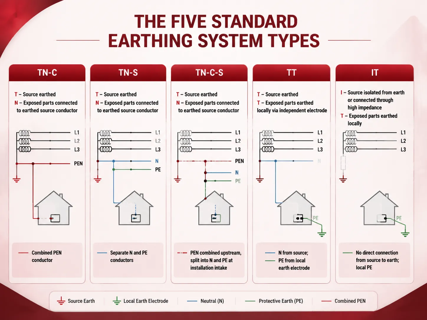
The IEC system uses a two‑letter code. The first letter — T or I — indicates how the supply source is connected to earth. The second letter — N or T — indicates how the installation’s exposed conductive parts are earthed. Additional letters describe the arrangement of the neutral and protective conductors. The table below summarises the five standard types.
| System | First Letter (Source Earth) | Second Letter (Installation Earth) | Neutral & PE Arrangement |
|---|---|---|---|
| TN-C | T — source earthed | N — exposed parts connected to the earthed source conductor | Combined PEN conductor (Protective Earth & Neutral) |
| TN-S | T — source earthed | N — exposed parts connected to the earthed source conductor | Separate N and PE conductors from source to load |
| TN-C-S | T — source earthed | N — exposed parts connected to the earthed source conductor | Combined PEN upstream, separated into N and PE at the installation intake |
| TT | T — source earthed | T — exposed parts earthed locally via an independent electrode | Separate N from source; PE from local earth electrode |
| IT | I — source isolated from earth or connected through a high impedance | T — exposed parts earthed locally | No direct connection from source to earth; local PE |
TN-C: The Combined PEN Conductor
The neutral and earth functions are combined into one conductor (the PEN) over the entire length from transformer to load in a TN–C system. This means copper is saved by using one conductor instead of two; however, it creates a specific hazard, as if the PEN conductor were to break or come apart, there would be full line voltage on all exposed metallic surfaces downstream of the break or separation. Because of the above point, TN–C generally is not permitted for building wiring past the point of service entrance and is also not permitted to be used for circuits that have RCDs on the load side. Presently, the majority of use of TN–C systems are only within the utility’s distribution networks, and even then only in certain countries.
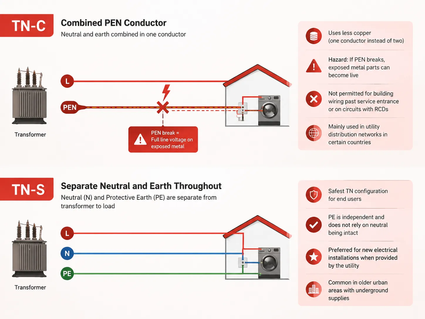
TN-S: Separate Neutral and Earth Throughout
In a TN-S system, there are two conductors (neutral and PE) running through the installation from the supply transformer. The PE connections to the earth path are independent and do not rely on the neutral being intact (i.e. broken neutral). TN-S is often referred to as the safest TN configuration/option for an end user and is the preferred way to set up or install new electrical services when the utility provides a separate earth conductor. In fact, many older urban areas that have underground electricity supplies are configured as TN-S.
TN-C-S: Protective Multiple Earthing (PME)
TN-C-S Protective Multiple Earthing (PME) is commonly used in UK homes. The PEN conductor is the path for the power supply and has the neutral and earth wire together from the transformer to the service head, this happens before the cable is separated out into individual earth and neutral wires at the service head and the earth is earthed to a local grounding electrode as a failsafe. The “multiple” means the PEN conductor is connected to the earth at multiple points. Providing that the PEN conductor is in good condition, this has the advantage of providing a low impedance fault current path through the system, enabling breaker devices to trip quickly. However, there is a risk of a PEN conductor fault, as with a TN-C system, resulting in an exposed part of the system becoming energised (potentially at a high voltage) if the PEN conductor should break before it is split into individual wires. One of the methods used to mitigate against this risk is bonding any other conductive parts of the building (water/gas pipes, reinforcing steel etc.) and using a local earthing electrode at the service head. Our guide on what size circuit breaker you need explains how fault loop impedance informs breaker selection, which is directly influenced by the earthing system.
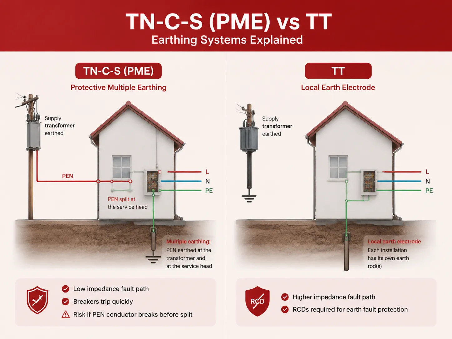
TT: Local Earth Electrode, No Earth from the Utility
The supply transformer in a TT system is earthed, but the earth connector for the installation is absent. Typically, the building has its own local earth electrode — which generally means one or more rods driven into the soil — and any exposed metalwork within the building is connected to the local earth electrode. Since the fault path back to the supply side is via the general mass of earth, the fault path has a relatively higher impedance than a plastic conductor. Further, due to the high impedance of the earth fault loop, a standard protective device may not operate sufficiently fast for an earth fault. Therefore, TT systems require the use of residual current detecting devices (RCDs) for earth fault protection. TT systems are typically used on rural overhead supplies throughout Europe and Australia, where there are individual earth stakes/rods for each residence.
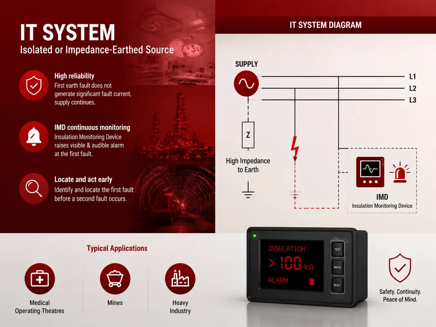
IT: Isolated or Impedance‑Earthed Source
An IT system separates the supply from earth in a manner that either isolates the supply from earth or connects it through a high impedance. The first earth fault that occurs on the IT system does not generate significant fault current thereby eliminating the need to disconnect the supply immediately. This is especially important within medical operating theatres, mines, and heavy industry; sudden loss of supply resulting from disconnecting the IT system could result in catastrophic consequences. An insulation monitoring device (IMD) continually monitors the resistance to earth in the IT system and raises a visible and audible alarm to identify and locate the first fault prior to the second fault on another phase and the creation of a short circuit. IT systems are not used in residential or general commercial installations as they are intended for use in high-reliability applications only.
TN-C-S vs. PME: The Same System, Different Jargon
TN-C-S and PME could be considered as two different words that can be used to describe the same type of electrical distribution arrangement, at least when it comes to the usage of those terms within the UK electrical context. They both refer to an arrangement of a combined PEN conductor that comes from the transformer, is split at the service head and has multiple bonded ground connections along the distribution system. The term that describes this system according to the International Electrotechnical Commission is TN-C-S. The UK term PME denotes that there are multiple grounding points; therefore, even though there are no electrical differences between the two terms, they are simply a difference in which terminology is used to describe this system. From an inspector or electrician’s perspective, the applicable standard is BS 7671 (the IEE Wiring Regulations), which uses the TN-C-S term and establishes specific bonding and grounding requirements for installations using this system.
TN-S vs. TT: When Earth Comes from the Grid or from a Rod
A major practical difference between the TN-S systems and TT systems is where the Earth Fault Current is directed. The TN-S provides a specific return path through a metallic conductor back to the transformer thereby ensuring a very low loop impedance for rapid magnetic tripping of the circuit breaker whereas the TT System relies on the Earth Fault Current returning through the Earth and back to the transformer using its Earth electrode therefore, the loop impedance will always be greater because of the resistance of the Earth path meaning the use of an RCD to provide an alternative means of disconnection is a requirement when using TT. When installing a new domestic property the utility will specify whether to use TN-S or TT and not the homeowner; hence, it is the responsibility of the installer to determine which type of system exists and choose appropriate protective devices.
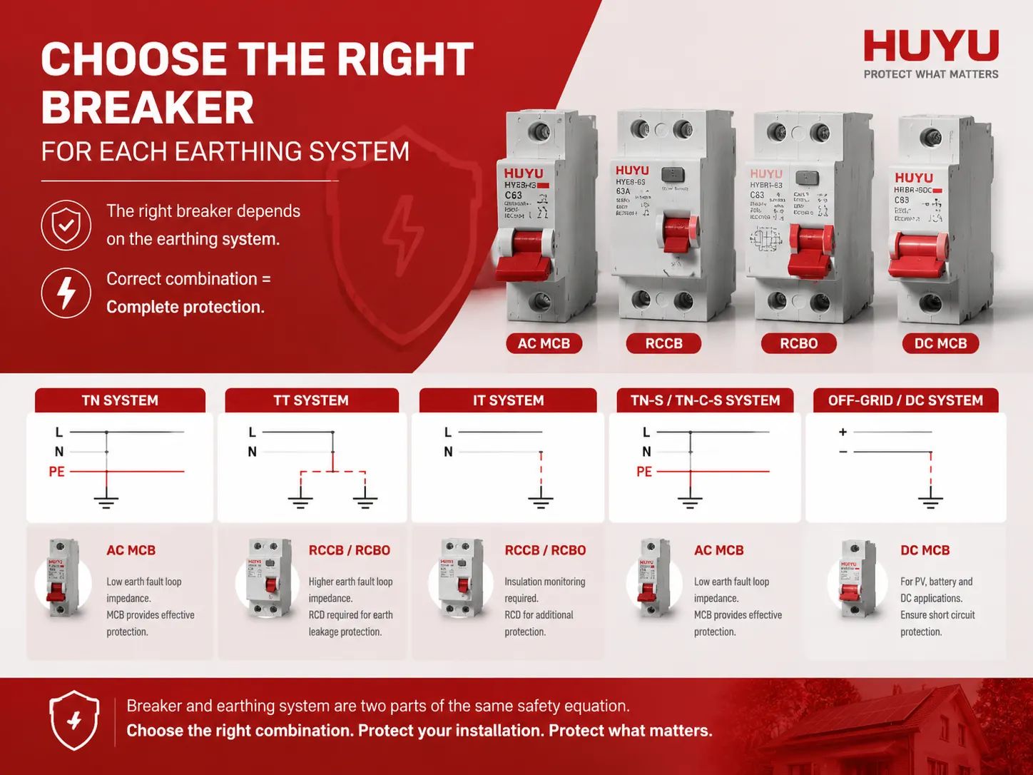
Choosing the Right Breaker for Each Earthing System
The Earthing System is an essential factor in determining the type and rating of protective device. In TN networks, with low earth fault loop impedance, a miniature circuit breaker (MCB) can provide automatic disconnection upon overload and short circuit to earth. However with TT networks, due to a higher earth fault loop impedance, a standard breaker may not comply with the required Disconnection times. Therefore an RCD (Residual Current Device) will also be required when protection against earth leakage is needed. HUYU can supply a full range of protective devices for all 5 types of earthing systems, including AC MCB’s for TN type installations, RCCB, and RCBO’s when protection against earth leakage is required, and DC MCB’s for the ever-increasing number of Off-Grid and Battery Backed installations. The breaker and the Earthing System represent two components of identical safety equation; if you specify one without the other, you will leave the installation unprotected.
Frequently Asked Questions
What are the 5 types of earthing systems?
According to IEC 60364 there are five types of earthing systems that are utilized to protect low voltages: TN-C, TN-S, TN-C-S, TT, and IT. They differ based on how the source is grounded, how the exposed component is grounded, and whether or not neutral is grounded together with protective conductors or separately.
What’s the difference between TNC and TNCS?
The TN-C system merges the neutral and protective earth conductors from the power source to the load. In contrast, with the TN-C-S system, the PEN (Protective Earth Neutral) conductors are combined only in the distribution section and split into separate neutral and earth conductors at the point of supply. Construction standards have rendered the use of TN-C obsolete for buildings; therefore almost all homes in the UK now use TN-C-S (PME) as their main electrical supply system.
What’s the difference between PME and TNCS?
Electrical characteristics are not dissimilar between these examples as the UK call the earthing arrangement “PME” while the IEC calls it “TN-C-S”. Both have the same meaning as they describe an earthing arrangement that uses a combined PEN conductor from the transformer at the service head and provide multiple local electricity/earthed supply connections along the distribution.
What is the TN-S and TT system?
TN-S TT separates neutral conductors from the transformer to the installation and has no earth connection to the supply from a utility company, using only local earthing electrodes on the installation itself. TN-S provides an earth fault loop impedance lower than that provided by TT, hence TT requires use of residual current devices (RCDs) or other means of protecting against earth faults.
References
- IEC 60364‑1 — Low‑voltage electrical installations — Part 1: Fundamental principles, assessment of general characteristics, definitions — International Electrotechnical Commission.
- Schneider Electric — Earthing Systems Application Guide — Practical guidance on protective device selection for TT, TN, and IT systems.
- BS 7671 — Requirements for Electrical Installations (IET Wiring Regulations) — Institution of Engineering and Technology, UK national standard.
- Electrical Construction & Maintenance (EC&M) — Articles on earthing and bonding in commercial and industrial installations.
Understanding the earthing system — whether it is TN-C, TN-S, TN-C-S, TT, or IT — is step one in designing a safe electrical installation. It determines the fault path, the disconnection time, and the type of protective device that must be installed. For the electrician, the inspector, or the engineer, the earthing system is not a detail to be checked at the end of the design. It is the starting point from which every other protection decision follows. HUYU supplies the breakers, RCDs, and RCBOs that match each earthing system’s specific requirements, ensuring that no matter how the building is earthed, the protection devices are correctly specified.