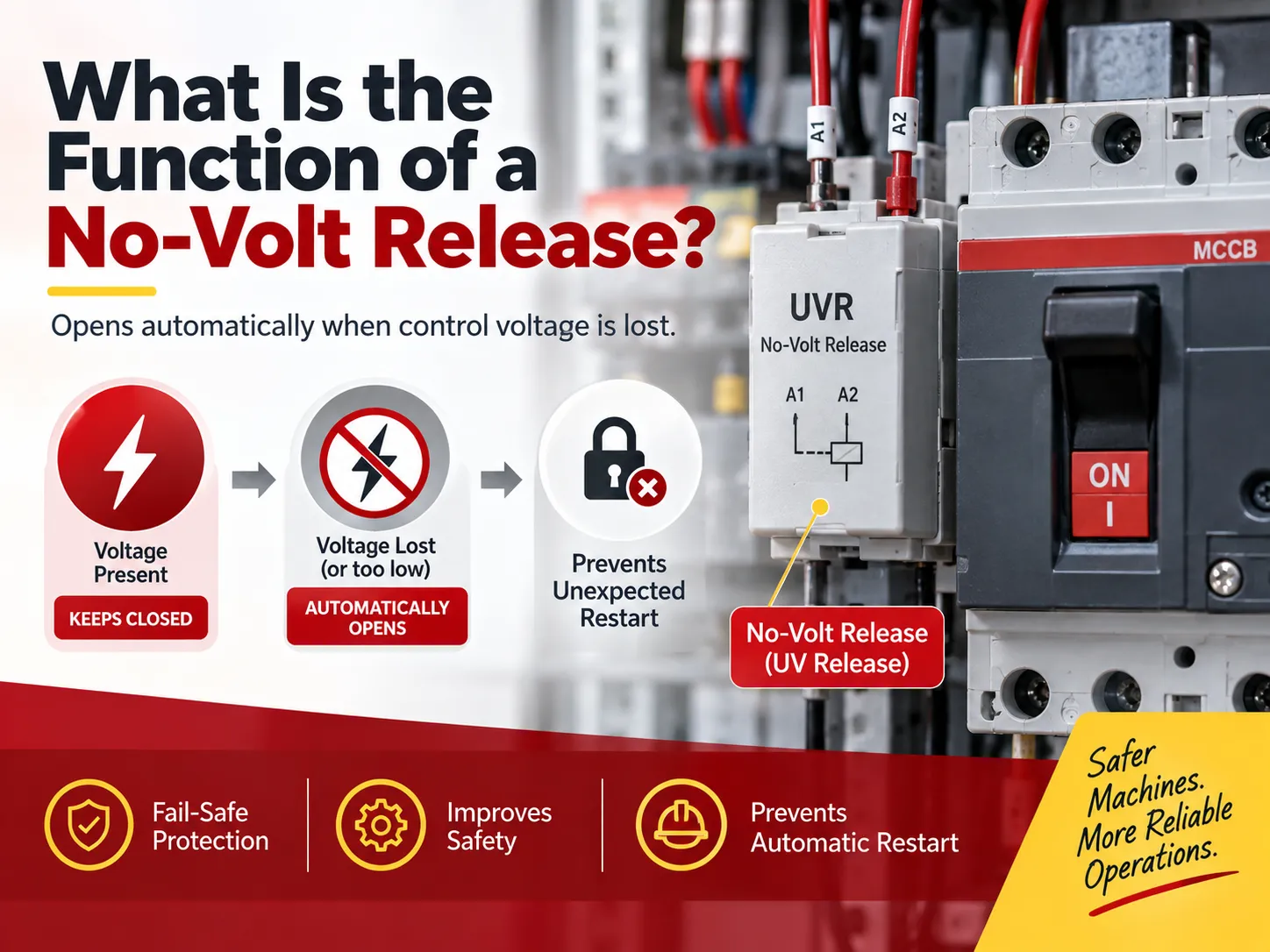
การปล่อยไม่มีแรงดันไฟฟ้า (no-volt release) ให้คำตอบกับคำถามที่ผู้ผลิตแผงควบคุมและผู้ออกแบบเครื่องจักรทุกคนต้องถามตัวเองในบางช่วงว่า: “จะเกิดอะไรขึ้นถ้ากำลังไฟฟ้าดับแล้วกลับมาใหม่?” การกล่าวว่า “เครื่องจักรจะเริ่มทำงานเองโดยอัตโนมัติ” ไม่เป็นที่ยอมรับสำหรับเครื่องจักรที่มีใบมีดหมุน สายพานลำเลียงที่มีโหลด และปั๊มแรงดัน การปล่อยไม่มีแรงดันไฟฟ้า (บางครั้งเรียกว่า ขดลวดไม่มีแรงดันไฟฟ้าหรือการปล่อยแรงดันไฟฟ้าต่ำ (UVR)) จะรักษาตำแหน่งของ “ฉันจะยังคงปิดอยู่จนกว่าจะได้รับคำสั่งให้เปิด” อุปกรณ์นี้ยังเป็นอุปกรณ์ความปลอดภัยที่มีราคาถูกที่สุดในแผงควบคุมและยังเป็นหนึ่งในอุปกรณ์ที่ถูกเข้าใจผิดมากที่สุดเนื่องจากฟังก์ชันเดียวกันนี้ทำงานแตกต่างกันอย่างมากขึ้นอยู่กับว่ากำลังใช้คอนแทคเตอร์หรือเบรกเกอร์วงจร คู่มือนี้ประกอบด้วยข้อมูลเกี่ยวกับการปล่อยไม่มีแรงดันไฟฟ้า การทำงาน การใช้งาน ความแตกต่างจากชันทริป ทางเลือก ความจำเป็นในการปล่อยไม่มีแรงดันไฟฟ้า และวิธีการระบุและทดสอบการปล่อยไม่มีแรงดันไฟฟ้าเพื่อไม่ให้ตกหลุมพรางของแรงดันขดลวด.
สรุปได้ว่า วัตถุประสงค์ของการปล่อยไม่มีแรงดันไฟฟ้าคือเพื่อให้แน่ใจว่าอุปกรณ์สวิตชิ่งจะคงอยู่ในตำแหน่งปิดตราบเท่าที่มีการจ่ายแรงดันควบคุม; หากแรงดันควบคุมดับ อุปกรณ์จะเปิดโดยอัตโนมัติตามมาตรฐาน IEC/EN 60947-2 เมื่อการสูญเสียแรงดันควบคุมต่ำกว่า 35% ของค่าที่กำหนด; ในทางตรงกันข้าม ในช่วงแรงดัน 35% ถึง 70% ของแรงดันที่กำหนด จะไม่มีระดับใดที่สามารถเปิดโดยอัตโนมัติได้ และเหนือกว่า 70% จะไม่มีการเปิดโดยอัตโนมัติ การปล่อยไม่มีแรงดันไฟฟ้าจะป้องกันการเริ่มต้นใหม่โดยอัตโนมัติของอุปกรณ์หลังจากการสูญเสียพลังงาน เนื่องจากเมื่อไฟฟ้ากลับมาใหม่หลังจากการสูญเสียพลังงาน การเริ่มต้นใหม่สามารถเกิดขึ้นได้เมื่อแรงดันกลับมาอยู่ที่ประมาณ 85% ของค่าที่กำหนด.
ฟังก์ชันหลัก
เวอร์ชันสั้น ๆ คือ การปล่อยไม่มีแรงดันไฟฟ้าทำให้การจ่ายแรงดันควบคุมเป็นเงื่อนไขที่ทำให้การควบคุมยังคงเปิดอยู่ แต่มีฟังก์ชันที่แตกต่างกันสี่แบบและควรชี้แจงว่าฟังก์ชันเหล่านั้นคืออะไร เนื่องจากโครงการต่าง ๆ จะต้องการฟังก์ชันที่แตกต่างกัน.
ป้องกันการเริ่มต้นใหม่โดยไม่คาดคิด. นี่คือวัตถุประสงค์หลักของการปล่อยไม่มีแรงดันไฟฟ้าและเป็นที่มาของชื่อ เมื่อเกิดความล้มเหลวในการจ่ายไฟ ทุกอย่างหลังจากจุดนี้จะหยุดทำงาน อย่างไรก็ตาม อันตรายเกิดขึ้นในวินาทีหลังจากที่ไฟฟ้ากลับมาใหม่ อุบัติเหตุคลาสสิกที่การปล่อยไม่มีแรงดันไฟฟ้าต้องการป้องกันคือเมื่อเลื่อย เครื่องผสม สายพานลำเลียง หรือเครื่องมือเครื่องจักรกลับมาทำงานอีกครั้งในขณะที่มือของผู้ปฏิบัติงานยังอยู่ในเครื่องจักร การปล่อยไม่มีแรงดันไฟฟ้าจะป้องกันไม่ให้วงจรปิดจนกว่าผู้ที่ทำงานจะกดปุ่มเริ่มต้น สิ่งนี้สำคัญที่จะต้องมีในมาตรฐานเครื่องจักรและเป็นสิ่งจำเป็นสำหรับเครื่องจักรอุตสาหกรรมส่วนใหญ่.
การสร้างการปิดเครื่องอัตโนมัติเมื่อแรงดันไฟฟ้าคงที่ต่ำ. มอเตอร์จะไม่ทำงานได้ดีเมื่อมีแรงดันไฟฟ้าต่ำกว่า มอเตอร์แต่ละตัวจะดึงกระแสไฟฟ้ามากขึ้นที่แรงดันต่ำกว่าเพื่อผลิตงานในปริมาณเท่าเดิมและทำให้เกิดความร้อนมากขึ้นในสายไฟ ซึ่งอาจทำให้ฉนวนไฟฟ้าเสียหายและอุปกรณ์ล้มเหลวได้ บทบาทของรีเลย์แรงดันต่ำ (UVR) คือการเปิดวงจรเพื่อป้องกันไม่ให้เกิดความล้มเหลวทางความร้อน.
การสร้างช่องทางความปลอดภัยแบบฮาร์ดไวร์. เนื่องจากการปล่อยแรงดันไฟฟ้าไม่มีแรงดันทำงานสัมพันธ์กับการขาดแรงดันไฟฟ้า เมื่อมีแรงดันไฟฟ้าปกติ อุปกรณ์ความปลอดภัยทุกชิ้นสามารถใช้เป็นวิธีการสร้างการปิดเครื่องฉุกเฉินได้ สวิตช์ความปลอดภัย สวิตช์ดึงสาย สวิตช์สัญญาณเตือนไฟไหม้ หรือการติดต่อกับระบบบริหารอาคาร จะทำให้วงจรเปิดขึ้นโดยธรรมชาติ สิ่งใดที่ทำให้สายไฟขาดจะสร้างการปิดเครื่องที่ปลอดภัย พฤติกรรมนี้เรียกว่า “fail-safe”
การยืนยันแรงดันไฟฟ้าที่มีสุขภาพดี ก่อนปิดวงจร. ในกรณีของแผนผังการโอนย้ายเครื่องกำเนิดไฟฟ้า จะมีความกังวลในการปิดสวิตช์หากไม่มีแรงดันไฟฟ้า UVR จะอนุญาตให้ยืนยันว่าแรงดันไฟฟ้ามีสุขภาพดี (มากกว่า 85% ของแรงดันที่กำหนด).
วิธีการทำงาน
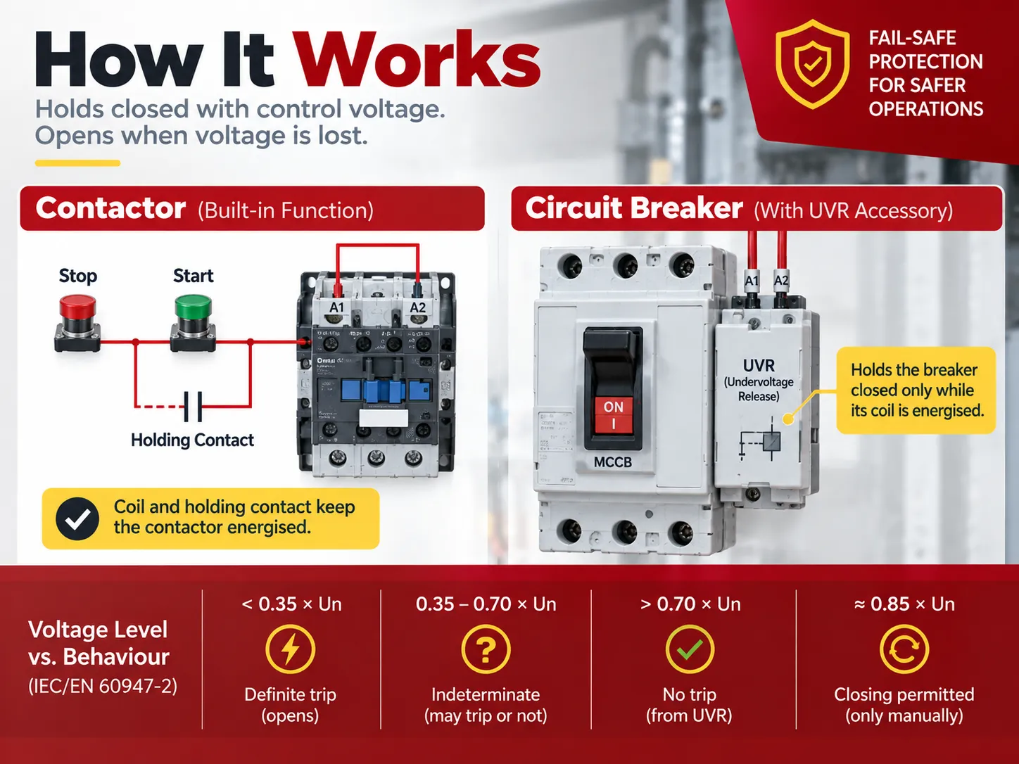
ในการกำหนดค่าคอนแทคเตอร์ หลักการนั้นง่ายมาก พลังงานจะถูกจ่ายให้กับขดลวดคอนแทคเตอร์โดยการกดสวิตช์เริ่มต้น และเมื่อคอนแทคหลักปิดลง คอนแทคเสริมที่ปกติเปิดซึ่งขนานกับสวิตช์เริ่มต้นจะปิดลงด้วย คอนแทคเสริมนี้ที่เรียกว่าคอนแทคถือครอง จะทำให้ขดลวดยังคงมีกระแสไฟฟ้าหลังจากผู้ปฏิบัติงานปล่อยปุ่ม ดังนั้น แม้ว่าจะปล่อยแล้ว ขดลวดยังคงมีเส้นทางสำหรับกระแสไฟฟ้า จึงทำให้วงจรถูกเก็บรักษาไว้โดยอัตโนมัติเนื่องจากไม่ต้องการพลังงานภายนอกเพื่อรักษาสถานะนี้ เนื่องจากแรงดันควบคุมเป็นตัวกระตุ้นอุปกรณ์ เราจึงสามารถกล่าวได้ว่าขดลวดทำหน้าที่เป็นการปล่อยแรงดันไฟฟ้าไม่มีแรงดัน ไม่จำเป็นต้องมีส่วนประกอบเพิ่มเติมในวงจร.
อย่างไรก็ตาม ในกรณีของเบรกเกอร์วงจร เราจะพบสถานการณ์ที่แตกต่างกัน และนี่คือที่มาของความสับสนส่วนใหญ่ เบรกเกอร์วงจรพึ่งพาตัวล็อคกลไก ซึ่งหมายความว่ามันจะอยู่ในตำแหน่งปิดอย่างไม่มีกำหนดโดยไม่ต้องจ่ายพลังงานให้กับวงจร ตรงกันข้าม กลไกความปลอดภัยที่เรียกว่าอุปกรณ์ปล่อยแรงดันต่ำในกรณีนี้ ต้องถูกเพิ่มเข้ามาเป็นโซลินอยด์ที่มีตัวล็อคซึ่งจะล็อคกลไกไว้เฉพาะเมื่อขดลวดของมันได้รับพลังงาน ข้อกำหนดของอุปกรณ์ดังกล่าวตามมาตรฐาน IEC/EN 60947-2 เหมือนกันกับผู้ผลิตรายใหญ่ทั้งหมด:
| แรงดันควบคุม (เป็นสัดส่วนของแรงดันขดลวดที่กำหนด) | พฤติกรรมของอุปกรณ์ |
|---|---|
| ต่ำกว่า 0.35 × Un | การตัดวงจรแน่นอน — โซลินอยด์ปล่อยและอุปกรณ์เปิดวงจร |
| ระหว่าง 0.35 ถึง 0.70 × Un | ไม่แน่นอน — อาจตัดวงจรหรือไม่ก็ได้; ช่วงนี้ไม่ได้ถูกกำหนดเป็นจุดข้อกำหนดโดยเจตนา |
| สูงกว่า 0.70 × Un | ไม่มีการตัดวงจรจากฟังก์ชันแรงดันต่ำ |
| ฟื้นฟูถึงประมาณ 0.85 × Un | อนุญาตให้ปิดวงจรอีกครั้ง — แต่ต้องทำโดยการปฏิบัติการอย่างตั้งใจเท่านั้น ไม่ใช่อัตโนมัติ |
จากตารางนั้น สามารถสรุปข้อสรุปที่ใช้งานได้จริงสองประการ ประการแรกคือแถบ 35-70% ที่ไม่แน่นอนหมายความว่า UVR ไม่สามารถนับได้ว่าจะตัดวงจรที่ระดับแรงดันไฟฟ้าใดระดับหนึ่ง; มันเป็นอุปกรณ์ที่ปลอดภัยในกรณีล้มเหลวเท่านั้น ไม่ใช่เครื่องตรวจสอบที่มีความแม่นยำ ประการที่สองคือในกรณีของการติดตั้งที่มีการร้องเรียนเป็นลายลักษณ์อักษรเกี่ยวกับแรงดันตกชั่วคราว มีหน่วยหน่วงเวลาให้เลือกใช้; หน่วยนี้จะอนุญาตให้การตัดวงจรถูกหน่วงเวลาในกรณีที่แรงดันตกต่ำเป็นเวลาต่ำกว่า 200 มิลลิวินาที ทำให้แรงดันตกชั่วคราวที่ไม่ส่งผลกระทบต่อกระบวนการไม่ทำให้โรงงานหยุดทำงาน การเลือกใช้ UVR แบบหน่วงเวลาในกรณีที่แรงดันตกบ่อยครั้งเป็นความแตกต่างระหว่างการให้การป้องกันที่มีประโยชน์และการให้สิ่งที่ผู้ปฏิบัติงานจะไม่ใช้.
สองรูปแบบ: คอนแทคเตอร์ กับ เบรกเกอร์
การเข้าใจว่าคุณกำลังใช้รูปแบบใดจะช่วยป้องกันข้อผิดพลาดในการกำหนดสเปคส่วนใหญ่ เนื่องจากสองคำนี้แตกต่างกันและไม่ได้ทำหน้าที่เดียวกันภายในระบบ.
| สตาร์ทเตอร์แบบคอนแทคเตอร์ | เบรกเกอร์วงจร | |
|---|---|---|
| กลไกการยึด | ขดลวดที่ถูกยึดด้วยไฟฟ้าพร้อมกับคอนแทคช่วยยึด | ตัวล็อคกลไก |
| สิ่งที่เกิดขึ้นเมื่อไฟฟ้าขาด | ขดลวดดับไฟ ฟ้าคอนแทคหลักเปิดโดยอัตโนมัติ | ยังคงปิดอยู่ — ตัวล็อคไม่ถูกกระทบจากการขาดไฟ |
| การปล่อยแรงดันไฟฟ้าไม่มีแรงดันจัดทำโดย | ขดลวดเอง โดยไม่มีค่าใช้จ่ายเพิ่มเติม | อุปกรณ์เสริมปล่อยแรงดันไฟฟ้าต่ำแยกต่างหากในช่องขดลวด |
| การเริ่มต้นใหม่หลังไฟดับ | เป็นไปไม่ได้หากไม่กดปุ่มเริ่มอีกครั้ง | เป็นไปไม่ได้เฉพาะเมื่อมีการติดตั้ง UVR; หากไม่มี UVR เบรกเกอร์จะยังคงปิดอยู่ |
| การใช้งานทั่วไป | สตาร์ทเตอร์มอเตอร์: DOL, สตาร์-เดลต้า, ซอฟต์สตาร์ทเตอร์, คอนแทคเตอร์ VFD | ตัวแยกเครื่องจักร, เบรกเกอร์วงจรมอเตอร์, เบรกเกอร์ ATS ขาเข้า, การป้องกันฟีดเดอร์ |
| มาตรฐานที่ใช้บังคับ | IEC/EN 60947-4-1 | IEC/EN 60947-2 |
ตัวอย่างกับคอนแทคเตอร์เกี่ยวข้องกับเหตุผลที่คำว่า “no-volt release” เป็นที่นิยมในมาตรฐานของอังกฤษและเครือจักรภพ; เพราะสตาร์ทเตอร์ DOL ทุกตัวมาพร้อมกับกลไกนี้โดยไม่คำนึงว่าสเปคนี้จะถูกกำหนดหรือไม่ จึงทำให้เราได้ตัวย่อ TONVR (thermal overload, no-volt release) เพื่ออธิบายการป้องกันมาตรฐานของสตาร์ทเตอร์ ตัวอย่างกับเบรกเกอร์เกี่ยวข้องกับเหตุผลที่สเปคเดียวกันนี้อาจมีค่าใช้จ่ายสูง; เพราะถ้าอุปกรณ์ป้องกันที่ใช้ปกป้องอุปกรณ์เป็นเบรกเกอร์แบบเคสขึ้นรูปแทนที่จะเป็นคอนแทคเตอร์ ฟังก์ชันปลอดภัยในกรณีล้มเหลวต้องซื้อแยกเป็นอุปกรณ์เสริม จากตัวอย่างเหล่านี้ สามารถสรุปกฎง่ายๆ ได้ว่า; หากอุปกรณ์ตัดการเชื่อมต่อเป็นคอนแทคเตอร์ ฟังก์ชันนี้ไม่มีค่าใช้จ่าย แต่ถ้าเป็นเบรกเกอร์ ผู้ใช้ต้องขอเข้าถึงส่วน UVR โดยเฉพาะและตรวจสอบว่ามีช่องว่างในโครงสำหรับขดลวดหรือไม่.
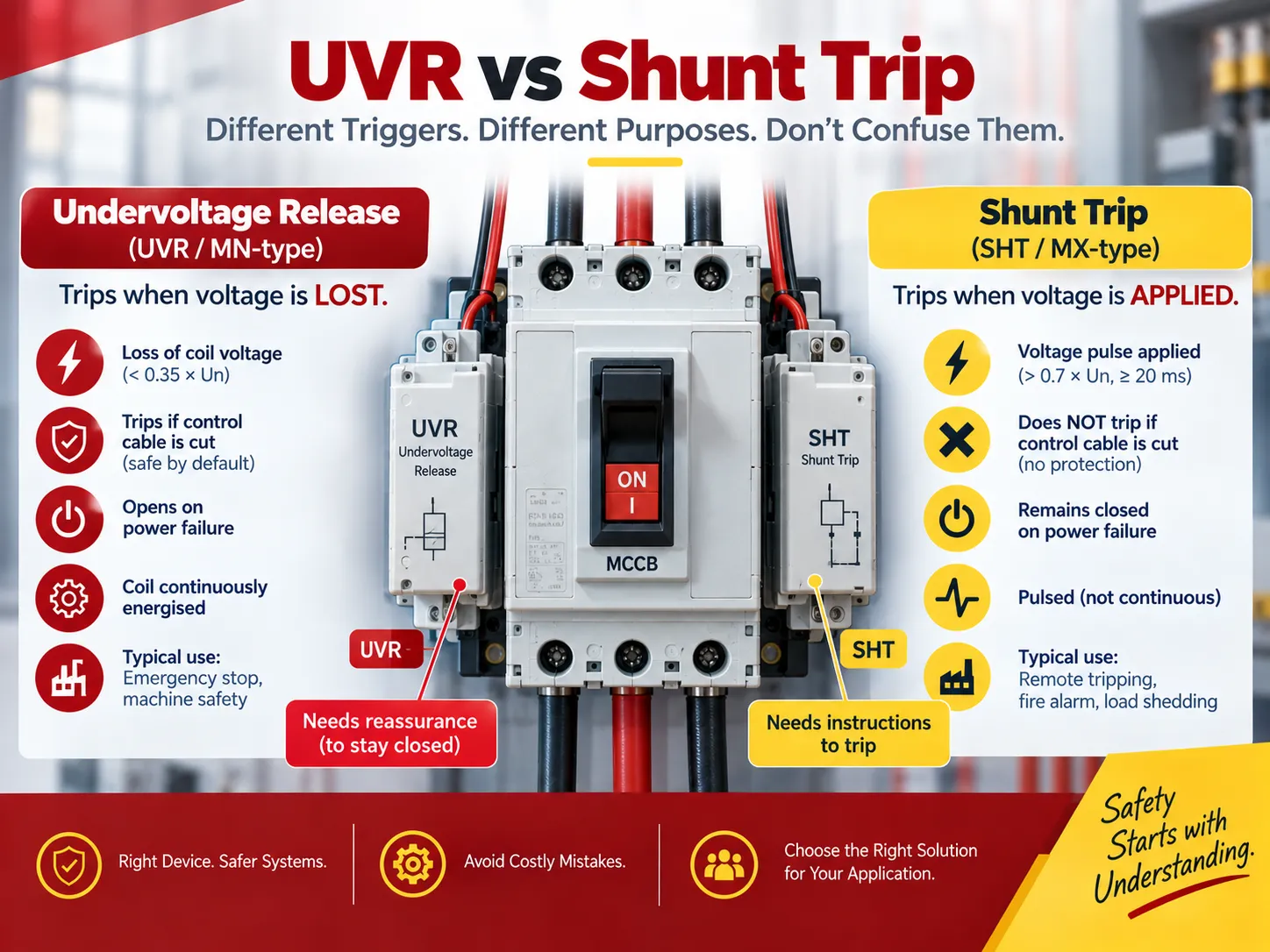
UVR กับ Shunt Trip
แม้ว่าจะดูคล้ายกันและติดตั้งในตำแหน่งเดียวกัน แต่ชิ้นส่วนเสริม shunt trip และ undervoltage release auxiliary มักถูกสับสนกันในใบสั่งซื้อเนื่องจากทำหน้าที่แตกต่างกันโดยสิ้นเชิง การสับสนระหว่างอุปกรณ์เสริมทั้งสองนี้เป็นอันตรายเพราะ shunt trip ไม่ได้ให้กลไกป้องกันใดๆ เมื่อสายควบคุมขาด.
| การปลดปล่อยแรงดันต่ำ (no-volt, UVR, ชนิด MN) | ชันท์ทริป (SHT, ชนิด MX) | |
|---|---|---|
| การกระตุ้น | การสูญเสียแรงดันขดลวด ต่ำกว่า 0.35 × Un | การใช้แรงดันสูงกว่า 0.7 × Un, เป็นพัลส์อย่างน้อย 20 มิลลิวินาที |
| พฤติกรรมเมื่อสายควบคุมถูกตัด | อุปกรณ์ตัดวงจร — ปลอดภัยโดยค่าเริ่มต้น | ไม่มีอะไรเกิดขึ้น — คำสั่งตัดวงจรไม่เคยมาถึง |
| พฤติกรรมเมื่อไฟฟ้าขัดข้อง | อุปกรณ์เปิดวงจร | อุปกรณ์ยังคงปิดวงจร |
| การปิดวงจรใหม่ | อนุญาตเฉพาะเมื่อแรงดันสูงกว่า ประมาณ 0.85 × Un, และเฉพาะโดยการกระทำที่ตั้งใจ | อนุญาตเมื่อมีการออกคำสั่งเท่านั้น |
| ต้องจ่ายไฟขดลวดอย่างต่อเนื่องหรือไม่? | ใช่ — นั่นคือวิธีที่อุปกรณ์ถูกยึดไว้ | ไม่ — เป็นการจ่ายไฟแบบพัลส์ |
| การใช้งานทั่วไป | วงจรหยุดฉุกเฉิน, ป้องกันการเริ่มต้นใหม่โดยไม่มีผู้ดูแล, ความปลอดภัยของเครื่องจักร, การอนุญาตแหล่งจ่ายไฟที่มีสุขภาพดีในระบบโอน | การตัดวงจรระยะไกลจากรีเลย์ป้องกัน, การเชื่อมต่อสัญญาณเตือนไฟไหม้, การลดโหลด, การตัดการเชื่อมต่อที่เริ่มโดย BMS |
วิธีง่ายๆ ในการจดจำความแตกต่างระหว่างอุปกรณ์เสริมทั้งสองคือ ชันท์ทริปต้องการคำสั่ง ในขณะที่การปล่อยแรงดันต่ำต้องการการยืนยัน กล่าวอีกนัยหนึ่ง ชันท์ทริปรอคำสั่งให้ตัดวงจร แต่การปล่อยแรงดันต่ำจะยึดอุปกรณ์ไว้จนกว่าไฟฟ้าจะขาด; อุปกรณ์จะเปิดทันทีเมื่อไฟฟ้าถูกตัด ตามที่กล่าวไว้ก่อนหน้านี้ ทั้งสองให้กลไกการตัดวงจรภายนอกที่ข้ามอุปกรณ์ตัดวงจรภายในแบบเทอร์มอล-แม่เหล็กหรืออิเล็กทรอนิกส์ของแผงควบคุม; อย่างไรก็ตาม มีเพียงหนึ่งเดียวที่ล้มเหลวอย่างปลอดภัย เมื่อวัตถุประสงค์คือความปลอดภัยของบุคลากร ความแตกต่างนี้คือจุดสำคัญ และควรสังเกตว่า การตัดวงจรเกินกระแสของเบรกเกอร์สามารถถูกกระตุ้นโดยหลายสภาวะ ซึ่งเป็นหัวข้อแยกต่างหากที่ครอบคลุมในคู่มือของเรา สาเหตุที่ทำให้เบรกเกอร์ตัดวงจร.
การใช้งานที่ใช้
การใช้งานแบ่งออกเป็นสองประเภท คือที่ต้องการความปลอดภัย และที่เน้นกระบวนการ ดังนั้นอุปกรณ์ที่ใช้ข้อกำหนดด้านความปลอดภัยจึงมีบทบาทอย่างมีประสิทธิภาพ.
- มอเตอร์สตาร์ทเตอร์ ชนิด DOL หรือ สตาร์-เดลต้า และมอเตอร์สตาร์ทเตอร์ชนิดซอฟต์สตาร์ทและ VFD ใช้คอนแทคเตอร์ที่ถูกยึดโดยแรงดันวงจรควบคุม ฟีเจอร์ไม่มีแรงดันป้องกันอุปกรณ์จำนวนมากจากการเริ่มต้นใหม่โดยไม่ตั้งใจ.
- เครื่องมือเครื่องจักรและอุปกรณ์งานไม้ เลื่อย, มิลล์, เครื่องกด และเครื่องเจาะ เป็นตัวอย่างที่ดีของความจำเป็นของอุปกรณ์นี้ ซึ่งออกแบบมาเพื่อป้องกันการเริ่มต้นใหม่ที่ไม่พึงประสงค์ในขณะที่ผู้ปฏิบัติงานเปลี่ยนเครื่องมือตัดหรือเอาเศษชิ้นงานออก กฎระเบียบความปลอดภัยของเครื่องจักรก็ระบุมาตรการความปลอดภัยเพื่อหลีกเลี่ยงการเริ่มต้นที่ไม่ต้องการ.
- วงจรหยุดฉุกเฉิน เมื่อ E-stop ถูกเดินสายเป็นการตัดวงจรในวงจรขดลวด แทนที่จะเดินสายเป็นอินพุต PLC จะกลายเป็นอุปกรณ์ล้มเหลวอย่างปลอดภัย อินพุต PLC อาจถูกอ่านผิด, สูญเสียแหล่งจ่ายไฟ หรือค้างในโมดูลที่ผิดพลาด; แต่คอนแทคต์แบบอนุกรมในวงจรควบคุมจะไม่เป็นเช่นนั้น.
- รอก, ลิฟต์ และเครน การสูญเสียแหล่งจ่ายไฟอาจทำให้เกิดการเริ่มต้นใหม่ที่ไม่ควบคุมและการตกของโหลดที่ไม่ควบคุม.
- การสูบน้ำโดยไม่มีผู้ดูแลและการปฏิบัติการระยะไกล ปั๊มบ่อ, สถานีสูบน้ำชลประทาน และสถานีสูบน้ำบูสเตอร์ระยะไกลทำงานโดยไม่มีผู้ปฏิบัติงานในสถานที่ สิ่งสุดท้ายที่ผู้ปฏิบัติงานต้องการคือปั๊มที่เริ่มทำงานอีกครั้งในท่อแห้งหรือท่อที่อุดตันเมื่อไฟฟ้ากลับมา.
- การทำงานของเครื่องกำเนิดไฟฟ้าและการโอนถ่ายอัตโนมัติ รีเลย์แรงดันต่ำจะทำหน้าที่เป็นการปิดกั้นอนุญาตจนกว่าการจ่ายไฟเข้าจะถูกตั้งขึ้นจริง.
- การล็อกระบบสัญญาณเตือนไฟไหม้และระบบบริหารอาคาร ในกรณีเกิดไฟไหม้ แผงควบคุมไฟจะตัดวงจรแรงดันควบคุม.
- การลดภาระโหลด เมื่อผู้ควบคุมสถานีไฟฟ้าหรือไซต์ต้องการให้วงจรเปิดเมื่อเกิดเงื่อนไขการจ่ายไฟ เส้นทางแรงดันควบคุมจะให้ตัวเลือกแบบเดินสายแข็ง.
สิ่งสำคัญที่ต้องทราบในอุปกรณ์จ่ายไฟคือการปลดแรงดันต่ำเป็นตัวเลือกหนึ่งในหลายตัวเลือกที่อยู่ในช่องเดียวกันกับรีเลย์เสริมและรีเลย์เตือนภัย ชันท์ทริป ตัวควบคุมมอเตอร์ และตัวควบคุมแบบหมุนด้วยมือ การกำหนดสเปคสำหรับเบรกเกอร์ที่มี UVR ต้องยืนยันการยืนยันชุดอุปกรณ์เสริมก่อนสั่งซื้อและตกลง: ว่าการป้องกันที่ติดตั้งเป็นเบรกเกอร์แบบเคสขึ้นรูปหรืออุปกรณ์ขนาดเล็กเป็นการตัดสินใจที่มีผลต่ออุปกรณ์เสริมที่มีอยู่ ตามที่อธิบายในคู่มือของเราเกี่ยวกับ ความแตกต่างระหว่าง MCCB และ MCB.
ทางเลือกและตัวแทน
ฟังก์ชัน fail-safe ไม่สามารถแทนที่ได้อย่างแท้จริง แต่สามารถเลียนแบบได้ด้วยผลิตภัณฑ์ย่อยต่างๆ ซึ่งแต่ละอย่างมีความเสี่ยงของตัวเอง.
| แนวทาง | สิ่งที่บรรลุ | การแลกเปลี่ยน |
|---|---|---|
| วงจรถือคอนแทคเตอร์ (รีเลย์ NO เสริมขนานกับปุ่มสตาร์ท) | การปลดแรงดันแบบคลาสสิก — การเริ่มต้นใหม่ต้องการการกระทำโดยเจตนา | ใช้ได้เฉพาะเมื่อโหลดถูกสวิตช์โดยคอนแทคเตอร์ ไม่ใช่โดยเบรกเกอร์ |
| อุปกรณ์เสริมปลดแรงดันต่ำบนเบรกเกอร์ | พฤติกรรม fail-safe เดียวกันบนอุปกรณ์ที่ล็อกด้วยกลไก | ค่าใช้จ่ายเพิ่มเติม ใช้ช่องคอยล์ ต้องการแหล่งจ่ายควบคุมที่จ่ายไฟอย่างต่อเนื่อง |
| ชันท์ทริปร่วมกับรีเลย์หรือโลจิก PLC | สามารถเลียนแบบการห้ามเริ่มใหม่โดยการเขียนโปรแกรม | ล้มเหลวไม่ปลอดภัย: หากโลจิกหรือแหล่งจ่ายไฟดับ เบรกเกอร์จะยังคงปิดอยู่ ไม่ยอมรับได้ในฐานะฟังก์ชันความปลอดภัย |
| รีเลย์ป้องกันมอเตอร์พร้อมการห้ามเริ่มใหม่ | การบล็อกการเริ่มต้นใหม่ด้วยอิเล็กทรอนิกส์หลังจากทริปหรือการสูญเสียแหล่งจ่ายไฟ มักมีการหน่วงเวลาปรับได้ | ขึ้นอยู่กับรีเลย์ที่ได้รับพลังงานและตั้งค่าอย่างถูกต้อง ไม่ใช่การรับประกันแบบเดินสายแข็ง |
| ซอฟต์สตาร์ทเตอร์หรือ VFD พร้อมการตรวจสอบแรงดันต่ำ | Configurable restart behaviour, including inhibited restart | Same dependency on electronics; also adds a variable to commissioning |
| Mechanically latched contactor | Retains its last state across a supply loss | The opposite behaviour — it can restart unexpectedly. Used deliberately where auto-restart is wanted, never as a safety device |
| Local isolator with lock-off | Personnel protection during maintenance | Protects the maintainer, not the operator during an unattended outage |
There is a pattern to the contents of the table that deserves to be underlined: while physical solutions guarantee the reliability of the system, electrical systems do not. Indeed, a loss of Control Voltage cannot be misinterpreted, while a PLC input can be read incorrectly. This is why the fail-safe principle suggests that there should always be a hard-wire option for anything that protects human life, while all other operational features can be accomplished electronically.
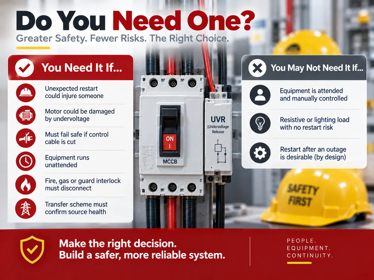
คุณต้องการใช้อุปกรณ์นี้หรือไม่?
To put it quite frankly, the chances are that you have one on any motor that is controlled by a contactor. The real issue is whether the other devices that aren’t controlled by a contactor need one. It would be beneficial to make a short checklist.
You will need one if any of the following is true: there’s a possibility of shock from an unexpected restart; the load is a motor and there is a chance of damage as a result of sustained undervoltage; the system must shut down safely if the control cable is cut; the application is run unattended; there is a requirement to disconnect the load under certain conditions (fire or gas); or if the transfer scheme must confirm that the source is in good health before closing.
You might not need one if the equipment in question is attended and under local manual control; if the load is a resistive circuit or if there are no safety hazards associated with the circuit; or if an inconvenience associated with restarting the system after a shutdown is acceptable and the design uses a latching mechanism. In this last instance, the need for interlocks should be addressed in the design decision, rather than merely allowing the default behavior of the protection device to govern.
Specifying and Testing
Four specification points confirm whether the device works properly.
- Connect the coil to the control power, not to the line power. This is the most common mistake made in the field, which results in the most misleading symptom – a brand new undervoltage trip that is “not working”. The voltage rating of the coil is not the same as that of the power poles of the breaker, but the voltage rating of the control voltage that is generated by the panel such as 24 – 30 V DC, 110 – 130 V AC/DC, or 220 – 240 V AC/DC. Check the voltage rating of the coil on the control circuit diagram in order to avoid premature assumptions about mechanical problems, and realize that many of the accessories that are returned because they “don’t work” are really just ones with the wrong coil.
- Select the time delay version with care. For applications that experience voltage dips less than 200 ms followed by a resumption of the process that is being controlled, the time delay version is more than likely to provide unnecessary tripping. For these applications, the instantaneous version would provide better protection.
- Confirm that closing is being inhibited. The purpose of the accessory is to not only trip but to refuse to close the circuit until after voltage is restored to 85 % of its rated voltage or higher. Verification should be done at commissioning rather than relying upon assumptions.
- Put the coil on a periodic test schedule. Manufacturers recommend the routine testing of trip coils – usually at least every six months – because a failed coil will not be distinguishable from a functioning coil until it is needed.Testing a suspect device for electrical integrity uses the same techniques as diagnosing any other breaker fault, which our guide to วิธีบอกว่าเบรกเกอร์เสีย covers in detail.
In cases where components are selected for a panel instead of being replaced in it, the protection layer should be specified as a package, including the breaker, associated accessories, and certified miniature devices installed on the same DIN rail.The HUM18-63N range is an example of the type of device that fills that role — a certified miniature circuit breaker line spanning 1P to 4P at 63 A with B, C, and D curves — and its HUM18-63N MCB product page shows the specification format buyers should expect to see documented.
Common Mistakes
- Ordering a shunt trip for use with a no-voltage release — both part numbers look similar and fit into the same terminal slots, but one method has a failsafe and the other does not.
- Hooking the coil to the line voltage. This guarantees either an burnt coil or a piece of equipment that stays open.
- Treating a mechanically-latched contactor as a failsafe. This design will actually keep its state, which is anything but what should happen.
- Making the emergency-stop function a purely software function on the PLC (no hard wiring). A software e-stop is not a failsafe e-stop; it is the hard wire break in the control circuit that guarantees the e-stop effect.
- Failing to implement the time-delay feature at a job site that is prone to fluctuations in voltage. The result is that your operation will experience nuisance shutdowns; once there are nuisance shutdowns occurring, the failover protection has been removed.
- Forgetting to include the accessory stack. A frame with one coil slot cannot house both a UVR and a shunt trip.
- Never performing a test on the coil itself. Failure is not visible UNTIL the time it becomes critical.
คำถามที่พบบ่อย
What is the main function of a no-volt coil?
The purpose of the no volt coil is to maintain energy to the controlling device as long as the control voltage is being supplied. If there is a loss of control voltage the coil will open the circuit to prevent the resetting of the equipment from taking place automatically as the electricity is restored. The coil does this directly in a contactor starter by supplying the control voltage that holds the contactor in, but in other cases, a separate accessory for undervoltage release is provided to hold the mechanical latching mechanism. There is an additional function of providing protection for continuous undervoltage which could cause overheating and damage motors.
What is the difference between NC and NO contacts?
A normally open (NO) contact is open when at rest and will close when it is actuated, whereas a normally closed (NC) contact is closed when at rest and will open when it is actuated. The circuit creates a two-step operation of the contacts: the start pushbutton and holding contacts are NO so that pressing the button establishes the circuit; while the stop button, emergency stop, and overload relay contacts are NC to allow normal operation as long as they remain closed. NC contacts are utilized in safety circuits because they result in an “off” condition in the event of an equipment failure instead of a “permissive” action.
What is a no volt contact?
In a contactor starter, the no-volt contact is the auxiliary normally-open contact in parallel with the start push button, also known as the holding contact. The start button is pressed to energize the coil and the main contacts close. The auxiliary contact also closes and provides a path for the coil current to the device. This feature makes the circuit self-sustaining. The no-volt release works because the coil current depends on the control power through the contact. Therefore, if there is any loss of the control power, the coil loses power. If the holding contact is faulty, the motor can be started only when the button is pressed.
Does a DOL starter already include no-volt release?
Yes, all direct-on-line starters with electromagnetically held contactors include no-volt release. The acronym used for thermal overload protection with no-volt release is TONVR. There is no need to purchase any additional auxiliary. The device becomes an extra line item in the case of a mechanically latched circuit breaker.
Why is my undervoltage release tripping for no apparent reason?
There are a few reasons for the trip that occur usually in this situation. If a trip happens when other equipment starts, the installation should be updated to have a time-delay release. If the coil power is shared with other loads, the no-volt release may operate within the indeterminate band. The problem can be resolved by having an auxiliary power supply to the no-volt release.
อ้างอิง
- Schneider Electric — Undervoltage and Shunt Trip Release Technical Documentation
- ABB — Circuit Breaker Accessories: Undervoltage Releases
- International Electrotechnical Commission — IEC 60947-2 and IEC 60947-4-1
- EUR-Lex — Machinery Directive 2006/42/EC
- Health and Safety Executive — Guidance on Machinery Safety and Unexpected Start-Up
สรุป
You may think the function of a no-volt release is quite extensive based only on its name, but this is not the case. Its high price is not an indication of the importance of the product either, since it does not properly check for voltage nor is it a general-purpose fall-back system. All it does is indicate when the control voltage is present so that it can be used as the initial condition for moving ahead when the voltage is safe and does not have to be checked. The no-volt release provides a great deal of benefit from this simple function. You will be able to restart following a power failure, disconnect during undervoltage conditions, use the no-volt release automatically in the event that the cable breaks and finally, prevent the circuit breaker from closing on no-load conditions. If you have a contactor starter, there is no additional cost for this no-volt relaunch system. If you have a circuit breaker, you will need to purchase it separately. Simply match the voltage of the coil and load, determine if there is a need for delay, and test the coil from time to time. As long as this approach is followed the consequences of having the no-volt release will be ensured, simulating what the safety system needs to provide.