เบรกเกอร์แบบโค้งอาจไม่ใช่เบรกเกอร์ชนิดใหม่ แต่หมายถึงเบรกเกอร์ที่เวลาตัดวงจรถูกกำหนดโดยเส้นโค้งที่ตั้งไว้ล่วงหน้าเพื่อให้สามารถตัดวงจรได้ทุกครั้งที่มอเตอร์ถูกเปิดใช้งานหรือคงปิดอยู่เมื่อสายไฟเกิดการลุกไหม้ ซึ่งง่ายต่อการสับสนเนื่องจากชื่อไม่ได้เกี่ยวข้องกับกระแสไฟฟ้าแต่เกี่ยวกับความเร็วในการตอบสนองของเบรกเกอร์ต่ออัตรากระแสไฟฟ้าที่กำหนดไว้ ดังนั้นไม่ว่าจะมีค่ากระแสไฟฟ้าเท่าใด การตัดวงจรผิดเส้นโค้งหมายความว่าไม่มีทางแก้ไขปัญหา ซึ่งเป็นเหตุผลที่การตัดวงจรที่น่ารำคาญเดียวกันซึ่งทำให้นักวิศวกรต้องหาตัวเบรกเกอร์ที่ใหญ่กว่าสามารถแก้ไขได้ง่ายเพียงแค่เปลี่ยนตัวอักษรหนึ่งตัวในชื่อของมัน คู่มือฉบับนี้ให้คำนิยามของเส้นโค้งการตัดวงจร อธิบายเส้นโค้งและระดับการตัดวงจร รวมถึงอธิบายว่าทำไมจึงจำเป็นต้องเลือกอย่างถูกต้อง.
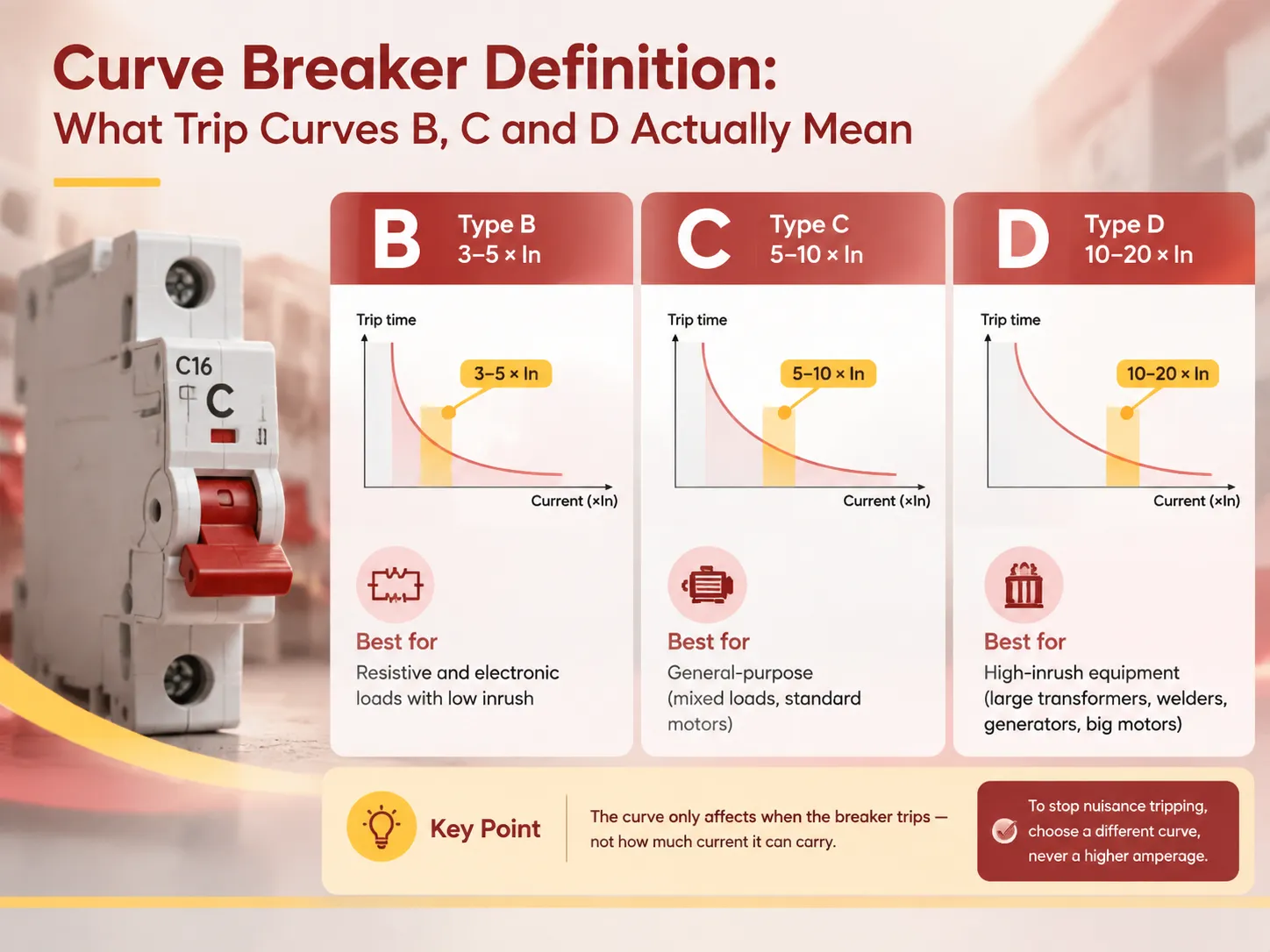
สรุปได้ว่า เบรกเกอร์แบบโค้งเป็นเบรกเกอร์วงจรชนิดเฉพาะที่ใช้เส้นโค้งมาตรฐาน (ระบุด้วย B, C หรือ D) แต่ละเส้นโค้งแสดงลักษณะการตัดวงจรตามเวลาต่อกระแสไฟฟ้า ซึ่งบ่งชี้การตั้งค่าของวาล์วแม่เหล็กตัดวงจร ชนิดของเบรกเกอร์วงจรที่แตกต่างกันมีการตั้งค่าการตัดวงจรที่แตกต่างกันตามกระแส In กระแสตัดวงจรของเบรกเกอร์แบบโค้งถูกกำหนดไว้ในตารางด้านล่าง โดยเบรกเกอร์ชนิด B ควรตัดที่ 3 ถึง 5 เท่าของ In, ชนิด C ที่ 5 ถึง 10 เท่าของ In และชนิด D ที่ 10 ถึง 20 เท่าของ In ตามมาตรฐาน IEC/EN 60898-1 ลักษณะทางความร้อนเหมือนกันสำหรับเบรกเกอร์ทั้ง 3 ชนิด อย่างไรก็ตาม กระแสตัดวงจรทันทีจะแตกต่างกัน ดังนั้น ตัวอย่างเช่น เบรกเกอร์ชนิด B สามารถใช้กับโหลดอิเล็กทรอนิกส์ที่มีกระแสเริ่มต้นต่ำ เบรกเกอร์ชนิด C สามารถใช้กับโหลดประเภทผสมและมอเตอร์ทั่วไป และสุดท้าย เบรกเกอร์ชนิด D เหมาะสำหรับอุปกรณ์ที่มีกระแสเริ่มต้นสูง.
ความหมายของ “Curve Breaker”
วลีนี้อธิบายถึงชนิดของเบรกเกอร์วงจรที่ทำงานตามลักษณะเวลาต่อกระแสที่ตั้งไว้ล่วงหน้า แทนที่จะเป็นจุดเดียวในเวลาที่ตัดสวิตช์ เบรกเกอร์วงจรขนาดเล็กแบบแม่เหล็กความร้อนแต่ละตัวมี “เส้นโค้ง” ของตัวเอง “เส้นโค้ง” คือชื่อของคำที่กำหนดพฤติกรรมของอุปกรณ์นี้เมื่อถูกกระแสไฟฟ้าต่าง ๆ.
มีสองกลไกที่รับผิดชอบต่อกระบวนการนี้ กลไกแรกคืออุปกรณ์ความร้อน – แถบไบเมทัลที่ถูกความร้อนโดยกระแสไฟฟ้าที่ไหลผ่าน หากเกิดการโอเวอร์โหลด แถบจะโค้งงออย่างช้า ๆ จนกระทั่งตัดวงจร ดังนั้นจึงมีความหมายในการป้องกันการร้อนเกินของสายไฟอย่างช้า ๆ และทำงานตามเส้นโค้งที่เรียกว่า inverse-time ซึ่งจะเร็วขึ้นเมื่อโอเวอร์โหลดเพิ่มขึ้น แต่ไม่ใช่ทันที กลไกที่สองคืออุปกรณ์แม่เหล็ก หรือโซลินอยด์ที่เพิ่มแรงที่ใช้กับวงจรเมื่อกระแสเพิ่มขึ้น นี่คือวิธีที่ส่วนทันทีของเส้นโค้งถูกสร้างขึ้น.
เนื่องจากกลไกทั้งสองถูกใช้สำหรับกลไกการสัมผัสเดียวกัน “เส้นโค้ง” จึงแสดงถึงพฤติกรรมของกลไกทั้งสองนี้รวมกัน: ความลาดเอียงแบบเวลาผกผันที่ราบรื่นที่ค่ากระแสต่ำซึ่งอุปกรณ์ความร้อนทำงาน และการลดลงเกือบตั้งฉากในส่วนนี้ของเส้นโค้งเมื่ออุปกรณ์แม่เหล็กเข้าควบคุม จุดที่เส้นโค้งเปลี่ยนเป็นแนวตั้งคือค่าที่กำหนดโดยตัวอักษรของมัน อุปกรณ์ที่สร้างตามหลักการนี้ และกลุ่มที่พวกมันเป็นสมาชิก ถูกครอบคลุมในคู่มือของเราเกี่ยวกับ การเลือก MCB และ MCCB.
ความหมายในทางปฏิบัติคือเส้นโค้งไม่ได้แสดงถึงคุณภาพหรือเรตติ้งกระแสไฟฟ้า ทั้งเบรกเกอร์ประเภท B 20A และเบรกเกอร์ประเภท D 20A มีค่ากระแส 20A ตลอดเวลาและปกป้องวงจรที่มีกระแส 20A ความแตกต่างเพียงอย่างเดียวระหว่างเบรกเกอร์ทั้งสองคือปริมาณกระแสที่พวกมันสามารถทนได้ในช่วงเวลาสั้น ๆ.
โครงสร้างของเส้นโค้งการตัดวงจร
เส้นโค้งการตัดวงจรถูกแสดงโดยใช้แกนลอการิทึม-ลอการิทึม แกนแนวนอนคือกระแสในอัตราส่วนของกระแสที่กำหนด; นั่นคือ I/In แกนแนวตั้งคือเวลาการตัดวงจร ซึ่งแสดงเป็นวินาทีตั้งแต่พันวินาทีจนถึงมิลลิวินาที.
| พื้นที่ของเส้นโค้ง | ช่วงกระแส | กลไก | สิ่งที่ป้องกัน |
|---|---|---|---|
| พื้นที่ไม่ตัดวงจร | สูงสุดประมาณ 1.13 × In | ไม่มีองค์ประกอบใดทำงาน | — กระแสโหลดปกติ |
| ช่วงความร้อนที่ไม่แน่นอน | 13-1.45 × In | ความร้อน; อาจตัดวงจรหรือไม่ตัดวงจรภายในเวลาที่กำหนด | การโอเวอร์โหลดขอบเขต |
| การตัดวงจรความร้อนที่แน่นอน | สูงกว่า 1.45 × In | ความร้อน, เวลาผกผัน | การโอเวอร์โหลดและความร้อนเกินของสายเคเบิล |
| การเปลี่ยนผ่านแม่เหล็ก | 3-5× (B), 5-10× (C), 10-20× (D) | แม่เหล็ก, ทันทีทันใด | การแยกแยะวงจรลัดวงจรและกระแสเริ่มต้นสูง |
แทนที่จะมองข้อมูลในตารางในแง่ของความปลอดภัย ควรถือว่าเป็นเรื่องของการแยกแยะ พื้นที่ความร้อนเหมือนกันสำหรับแต่ละเส้นโค้งเนื่องจากการปกป้องสายเคเบิลเป็นปัญหาทั่วไปไม่ว่าจะเป็นประเภทโหลดใด ในพื้นที่แม่เหล็กเป็นหน้าที่ของผู้ผลิตที่จะตัดสินใจว่าอุปกรณ์ควรตัดวงจรในกรณีกระแสต่ำในลักษณะที่อุปกรณ์ที่ไวต่อการปกป้องได้รับการปกป้องแต่กระแสเริ่มต้นที่ยอมรับได้ทั้งหมดถูกละเลย หรือในทางกลับกัน – ตัดวงจรช้าเพื่อให้กระแสเริ่มต้นทั้งหมดได้รับการยอมรับโดยยอมรับว่าอุปกรณ์จะตอบสนองต่อความผิดปกติกระแสเกินจริงช้าลง ตัวอักษรของเส้นโค้งคือบันทึกของการเลือกนี้.
ควรชี้แจงจุดสำคัญเนื่องจากแสดงถึงความเกี่ยวข้องในทางปฏิบัติของประเด็นทั้งหมดเกี่ยวกับการเลือกเส้นโค้ง กระแสเริ่มต้นเป็นปรากฏการณ์จริงและปกติ มอเตอร์เหนี่ยวนำ AC ทั่วไปจะใช้กระแสตั้งแต่ห้าถึงแปดเท่าของกระแสที่กำหนดในช่วงเวลาสั้น ๆ หลังจากเริ่มทำงาน หม้อแปลงเมื่อเชื่อมต่อกับกริดอาจใช้กระแสตั้งแต่สิบถึงสิบสี่เท่าของกระแสที่กำหนดในช่วงรอบแรก หากค่ากระแสต่ำกว่าค่าที่อ่านเหล่านี้ อุปกรณ์จะตัดวงจรทุกครั้งแม้ไม่มีความผิดปกติ หลักการเดียวกันควรใช้กับการควบคุมการสัมผัสพร้อมกับอุปกรณ์ป้องกัน เนื่องจากพวกมันทำหน้าที่สวิตชิ่งแต่ไม่กำจัดความผิดปกติ.
เส้นโค้งมาตรฐาน
IEC/EN 60898-1 กำหนดเส้นโค้งสามแบบที่ใช้ในงานติดตั้งภายในบ้านและงานพาณิชย์ขนาดเล็กส่วนใหญ่.
| เส้นโค้ง | เกณฑ์การตัดวงจรด้วยแม่เหล็ก | เวลาตัดวงจรทั่วไปที่เกณฑ์ | ออกแบบสำหรับ | การใช้งานทั่วไป |
|---|---|---|---|---|
| ประเภท B | 3-5 × ฉันn | 1 วินาทีหรือต่ำกว่าที่ปลายบน | โหลดที่มีแรงกระชากต่ำ | วงจรไฟส่องสว่าง, การให้ความร้อนแบบต้านทาน, ปลั๊กไฟในงานบ้าน, อุปกรณ์ PLC และเครื่องมือวัด, วงจรควบคุม |
| ประเภท C | 5-10 × ฉันn | 1 วินาทีหรือต่ำกว่าที่ปลายบน | โหลดเหนี่ยวนำและโหลดผสม | มอเตอร์มาตรฐาน, ปั๊ม, พัดลม, HVAC, วงจรปลั๊กไฟเชิงพาณิชย์, การกระจายไฟฟ้าอุตสาหกรรมทั่วไป |
| ประเภท D | 10-20 × ฉันn | 1 วินาทีหรือต่ำกว่าที่ปลายบน | แรงกระชากสูงมาก | หม้อแปลงขนาดใหญ่, เครื่องเชื่อม, อุปกรณ์เอกซ์เรย์, เครื่องกำเนิดไฟฟ้า, มอเตอร์ขนาดใหญ่, เครนและลิฟต์, เครื่องอัดอากาศ |
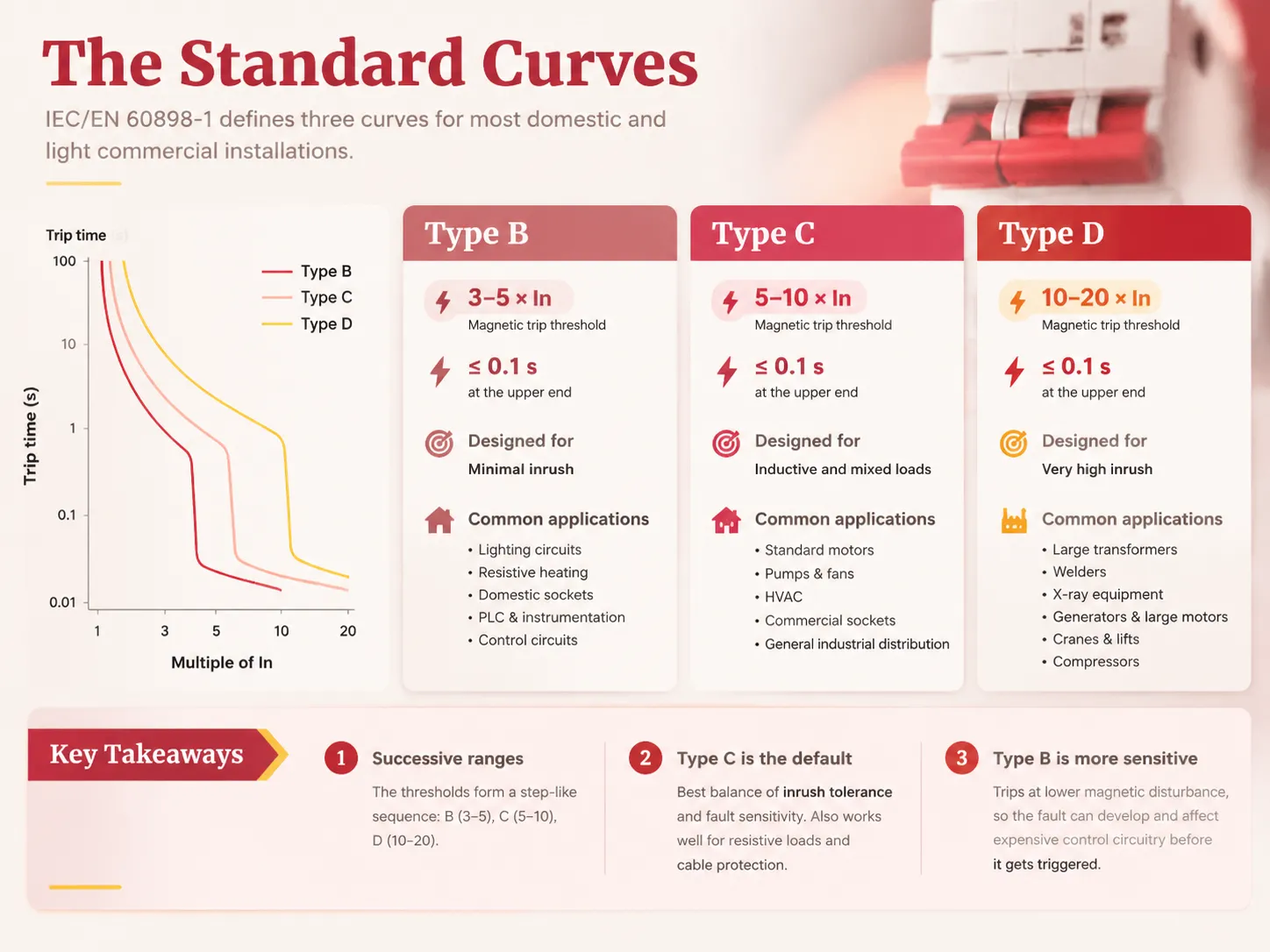
วิธีที่มีประสิทธิภาพในการติดตามลำดับชั้นคือช่วงตัวเลขมักจะต่อเนื่องกัน หมายความว่าเส้นโค้งจะเหมือนขั้นบันไดในระดับความทนทาน ใน B จำนวนครั้งที่กระแสไฟฟ้าสามารถเพิ่มขึ้นได้ประมาณสามถึงห้า ในขณะที่ใน C จำนวนนี้อยู่ระหว่างห้าถึงสิบ และใน D อยู่ระหว่างสิบถึงยี่สิบ เหนือเกณฑ์ ทุกอย่างจะตอบสนองเกือบจะทันที แต่ต่ำกว่าเกณฑ์ ทุกอย่างต้องผ่านตัวกลางความร้อนที่ช้ากว่า หากสามารถประมวลผลได้.
มีสองประเด็นเกี่ยวกับประเภท C ที่ควรสังเกต ประการแรก ประเภท C เป็นตัวเลือกเริ่มต้นสำหรับอุปกรณ์เชิงพาณิชย์และการผลิตส่วนใหญ่ในอุตสาหกรรม เนื่องจากมีความสมดุลที่ดีระหว่างระดับความทนทานต่อแรงกระชากและระดับความไวต่อความผิดปกติ นอกจากนี้ ยังไม่ใช่ตัวเลือกที่ไม่ดีสำหรับโหลดแบบต้านทานเพราะยังทำงานได้ดีสำหรับการป้องกันสายเคเบิล เหตุผลหลักในการใช้ประเภท B คือปัจจัยความไว: จะตัดวงจรเมื่อมีการรบกวนแม่เหล็กต่ำกว่า และด้วยเหตุนี้จึงสามารถปล่อยให้ความผิดปกติเกิดขึ้นและส่งผลกระทบต่อวงจรควบคุมที่มีราคาแพงก่อนที่อุปกรณ์ประเภท B จะทำงาน.
เส้นโค้งและรูปแบบอื่น ๆ
B, C และ D เป็นชุดมาตรฐาน แต่มีลักษณะอื่น ๆ สำหรับปัญหาเฉพาะบางอย่าง.
| เส้นโค้ง | เกณฑ์แม่เหล็ก | การใช้งานที่ตั้งใจ |
|---|---|---|
| ประเภท A | 2-3 × ฉันn | โหลดเซมิคอนดักเตอร์และอิเล็กทรอนิกส์ที่ต้องการการป้องกันวงจรลัดวงจรที่มีความไวสูง; วงจรลัดวงจรในสายเคเบิลยาว |
| ประเภท Z | 2-3 × ฉันn | วงจรอิเล็กทรอนิกส์และควบคุมที่ความไวเป็นสิ่งสำคัญ; เทียบเท่ากับประเภท A แต่มีมาตรฐานที่แตกต่างกัน |
| ประเภท K | 8-12 × ฉันn | มอเตอร์, หม้อแปลง และอุปกรณ์ที่มีกระแสเริ่มต้นสูงซึ่งประเภท D จะไวต่อการทำงานน้อยเกินไป |
| ประเภท MA | แม่เหล็กเท่านั้น ประมาณ 12 × In | การป้องกันวงจรมอเตอร์ที่การโอเวอร์โหลดถูกจัดการโดยรีเลย์โอเวอร์โหลดแยกต่างหาก; ไม่มีองค์ประกอบความร้อน |
| เส้นโค้งปรับได้ (MCCB) | ปรับได้ในสนาม | เบรกเกอร์แบบเคสขึ้นรูปที่เส้นโค้งและเรตติ้งถูกตั้งค่าให้เหมาะสมกับการติดตั้งและสามารถประสานงานกับอุปกรณ์ด้านบนได้ |
ความแตกต่างระหว่างตระกูลอุปกรณ์มีความสำคัญเนื่องจากเส้นโค้งที่มีอยู่จะขึ้นอยู่กับมาตรฐานที่ใช้ในการผลิตเบรกเกอร์ เบรกเกอร์วงจรขนาดเล็กที่เป็นไปตาม IEC 60898-1 ใช้เส้นโค้งคงที่โดยไม่มีความเป็นไปได้ในการปรับจากเส้นโค้งในตระกูล B, C หรือ D ในขณะที่เบรกเกอร์วงจรแบบเคสขึ้นรูปที่เป็นไปตาม IEC 60947-2 มักจะมีโอกาสในการปรับตั้งค่าทางแม่เหล็กและความร้อนบางส่วน ซึ่งสร้างโอกาสในการซิงโครไนซ์ทั่วทั้งระบบจำหน่ายแทนที่จะเป็นตัวเลือกคงที่ การตัดสินใจระหว่างตระกูลอุปกรณ์เกี่ยวข้องกับเรตติ้ง ระดับความผิดพลาด และการปรับตั้งค่า ไม่ใช่การเลือกเส้นโค้ง.
เส้นโค้ง B เทียบกับเส้นโค้ง C
นี่คือการเปรียบเทียบที่ใช้กันทั่วไปที่สุด และคำตอบขึ้นอยู่กับกระแสเริ่มต้นเกือบทั้งหมด.
| ประเภท B | ประเภท C | |
|---|---|---|
| ช่วงการตัดวงจรแม่เหล็ก | 3-5 × ฉันn | 5-10 × ฉันn |
| การตอบสนองต่อ 6 × In กระแสกระชาก | ตัดวงจรทันทีที่ส่วนบนของช่วง | อาจทนได้; ตัดวงจรเฉพาะเมื่อเกิน 5 × ขึ้นอยู่กับอุปกรณ์แต่ละตัว |
| ความไวต่อความผิดพลาดจริง | สูงกว่า — ตรวจจับวงจรลัดวงจรที่มีกำลังต่ำกว่า | ต่ำกว่า — วงจรลัดวงจรที่มีกำลังต่ำอาจถูกปล่อยให้เป็นหน้าที่ขององค์ประกอบความร้อน |
| ความเสี่ยงในวงจรมอเตอร์ | ความเสี่ยงสูงของการตัดวงจรรบกวนทุกครั้งที่เริ่มทำงาน | เหมาะสมในกรณีส่วนใหญ่ |
| ความเสี่ยงในวงจรไฟส่องสว่างหรืออิเล็กทรอนิกส์ | ไม่มี; เหมาะสม | อาจพลาดการตรวจจับความผิดพลาดที่กำลังพัฒนา |
| ข้อกำหนดทั่วไป | ไฟส่องสว่างในบ้าน, ปลั๊กไฟ, แผงควบคุม, เครื่องมือวัด | มอเตอร์, ปั๊ม, HVAC, การจำหน่ายเชิงพาณิชย์และอุตสาหกรรมทั่วไป |
น่าสังเกตว่ามีการทับซ้อนกันระหว่างสองช่วง: อุปกรณ์ที่อยู่ตรงกลางของช่วงประเภท B (4 × In) ตัวอย่างเช่น ไม่ได้ห่างจากอุปกรณ์ที่อยู่ที่ขอบล่างของช่วงประเภท C (5 × In) มากนัก และในความเป็นจริงช่วงเหล่านี้ควรถูกมองว่าเป็นช่วงค่าที่กว้าง ไม่ใช่จุดที่แม่นยำ เนื่องจากความคลาดเคลื่อนในการผลิต นี่คือเหตุผลที่บางครั้งการตัดวงจรรบกวนสามารถหลีกเลี่ยงได้โดยการเปลี่ยนผู้ผลิต ไม่ใช่เส้นโค้ง แม้ว่าการดำเนินการที่ถูกต้องควรใช้เส้นโค้งที่เหมาะสมจากข้อมูลที่เผยแพร่โดยผู้ผลิต.
เมื่อโหลดอยู่ใกล้กับขอบเขต — เช่น มอเตอร์ที่เริ่มต้นด้วยกระแสที่อยู่ตรงขอบของแถบประเภท C — ต้องตรวจสอบข้อกำหนดกับข้อมูลกระแสเริ่มต้นจริงของอุปกรณ์โดยไม่คำนึงถึงค่าที่ใช้ในการคำนวณ ในความเป็นจริง การเลือกเส้นโค้งโดยอาศัยกฎง่ายๆ แล้วพบหลังการติดตั้งว่าไม่ทำงาน อาจเป็นสาเหตุที่พบบ่อยที่สุดที่ทำให้ต้องเปิดตู้ควบคุม หลักการเดียวกันในการจับคู่เครื่องมือกับโหลดใช้กับการกำหนดขั้ว และตรรกะการเลือกสำหรับเรื่องนี้ได้ระบุไว้ในคู่มือของเราเกี่ยวกับ เบรกเกอร์ขั้วเดียวและขั้วคู่.
คำถามเกี่ยวกับ “เส้นโค้ง AC”
ไม่มีคำจำกัดความของ “เส้นโค้ง AC” ใน IEC 60898-1 และเป็นเรื่องสำคัญที่จะต้องชี้แจงเพราะคำนี้ถูกใช้ในทางปฏิบัติ คำว่า “เส้นโค้ง AC” มักหมายถึงหนึ่งในสองสิ่งต่อไปนี้.
- สิ่งแรกคือการจำแนกเบรกเกอร์ที่ได้รับการจัดอันดับสำหรับ AC และไม่ใช่สำหรับ DC นี่เป็นประเด็นที่ถูกต้องแต่เกี่ยวข้องกับการจัดอันดับของอุปกรณ์มากกว่าการจำแนกตัวเอง เบรกเกอร์ AC และ DC มีการออกแบบที่แตกต่างกัน เนื่องจากการดับประกายไฟในวงจร DC นั้นยากกว่าอย่างมาก เพราะกระแสไม่ถึงศูนย์สองครั้งในหนึ่งรอบ จึงไม่มีจุดธรรมชาติที่ประกายไฟดับลง ดังนั้น เบรกเกอร์ที่จัดอันดับสำหรับ DC จึงมีการออกแบบช่องทางประกายไฟ ขั้ว และระบบแม่เหล็กที่แตกต่างกัน รวมถึงเส้นโค้งที่เผยแพร่ต่างกัน การใช้เบรกเกอร์ที่จัดอันดับสำหรับ AC ในวงจร DC เป็นผลจากความผิดพลาดในการใช้งานมากกว่าความผิดพลาดของเส้นโค้ง.
- ความหมายที่สองของคำนี้คือความเข้าใจผิดเกี่ยวกับประเภท C ในการสนทนา ความสับสนนี้เกิดขึ้นง่ายในเวิร์กช็อปที่วุ่นวายและข้ามพรมแดนทางภาษา ในกรณีที่มีการใช้งาน DC จริง — เช่น แผงโซลาร์เซลล์ แบตเตอรี่ การขับเคลื่อน DC พลังงานโทรคมนาคม — ควรใช้การจัดอันดับและเส้นโค้ง DC ที่เหมาะสม และขั้วอาจมีความสำคัญโดยรวม หากข้อกำหนดระบุว่า “เส้นโค้ง AC” ควรตรวจสอบความหมายที่แท้จริงและยืนยันการจัดอันดับของอุปกรณ์ก่อนสั่งซื้อ.
วิธีการเลือกเส้นโค้ง
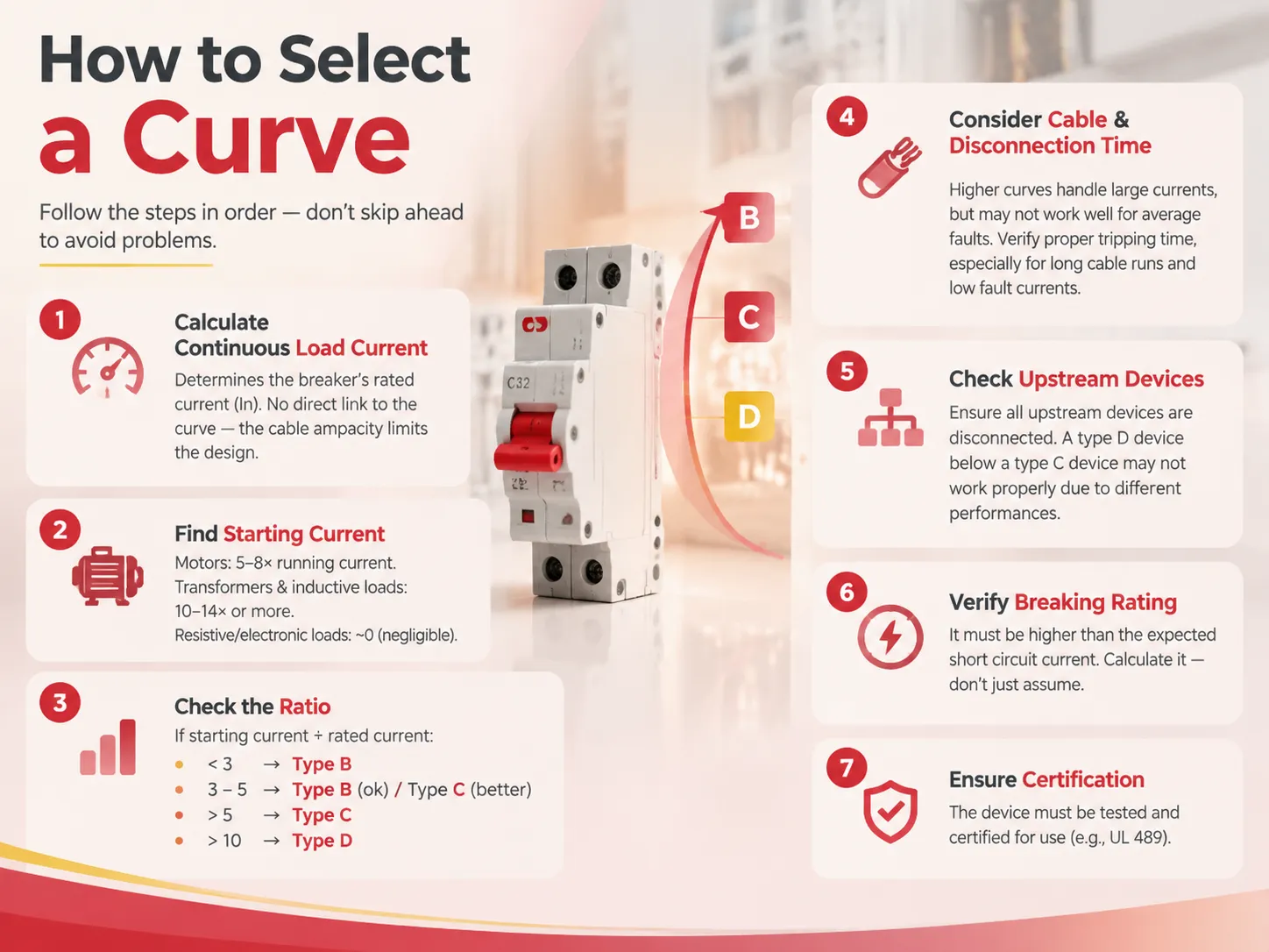
กระบวนการเลือกเส้นโค้งที่เหมาะสมเป็นขั้นตอนง่ายๆ ควรดำเนินการตามลำดับเพราะการข้ามการเลือกเส้นโค้งก่อนการประเมินขนาดสายเคเบิลอาจเป็นแหล่งปัญหาได้.
- คำนวณกระแสโหลดต่อเนื่อง ซึ่งกำหนดค่ากระแสจัดอันดับ (In) ของเบรกเกอร์ แต่ไม่มีความเกี่ยวข้องกับเส้นโค้งของอุปกรณ์ เบรกเกอร์ถูกออกแบบมาเพื่อปกป้องสายเคเบิล ซึ่งหมายความว่ากำลังไฟฟ้าของสายเคเบิลเป็นปัจจัยจำกัดในกระบวนการนี้.
- หาค่ากระแสเริ่มต้นของสมาชิกทั้งหมดในวงจร ในกรณีของมอเตอร์จะเท่ากับห้าถึงแปดเท่าของกระแสทำงาน ขณะที่หม้อแปลงและโหลดเหนี่ยวนำประเภทเดียวกันอาจสร้างกระแสได้ 10 ถึง 14 เท่าหรือมากกว่ากระแสจัดอันดับ การมีส่วนร่วมจากโหลดตัวต้านทานและอิเล็กทรอนิกส์สามารถละเลยได้เนื่องจากเกือบเป็นศูนย์.
- คำนวณอัตราส่วนของกระแสเริ่มต้นต่อกระแสที่กำหนด หากอัตราส่วนต่ำกว่าสามเท่าของกระแสที่กำหนด ประเภทโค้ง B เหมาะสมสำหรับจัดการกับปัญหานี้ หากอัตราส่วนอยู่ระหว่างสามถึงห้า ประเภท B สามารถใช้ได้แต่ประเภท C จะเป็นตัวเลือกที่น่าเชื่อถือมากกว่า หากอัตราส่วนสูงกว่าห้า ประเภท C เป็นตัวเลือกที่ดีที่สุด หากการคำนวณแสดงอัตราส่วนสูงกว่าสิบเท่า ควรใช้โค้งประเภท D.
- ตรวจสอบให้แน่ใจว่าพิจารณาประเภทของสายเคเบิลและเวลาการตัดการทำงาน โค้งประเภทที่สูงกว่าจะทำงานได้ดีกับกระแสไฟฟ้าขนาดใหญ่ แต่ในขณะเดียวกันจะไม่ทำงานอย่างถูกต้องในกรณีกระแสลัดวงจรเฉลี่ย ตรวจสอบให้แน่ใจว่าการตัดวงจรเกิดขึ้นในเวลาที่เหมาะสมแม้ในกรณีกระแสลัดวงจรต่ำ โดยเฉพาะในกรณีที่สายเคเบิลมีความยาวมาก.
- ตรวจสอบให้แน่ใจว่าอุปกรณ์ทั้งหมดที่อยู่ด้านบนของอุปกรณ์นี้ในวงจรถูกตัดการทำงานในขณะที่ใช้เบรกเกอร์นี้ ในกรณีที่อุปกรณ์ประเภท D ติดตั้งอยู่ด้านล่างอุปกรณ์ประเภท C ในวงจร อุปกรณ์เหล่านี้อาจไม่ทำงานอย่างถูกต้องเนื่องจากประสิทธิภาพที่แตกต่างกันของสองประเภทภายใต้กระแสลัดวงจรที่กำหนด.
- ตรวจสอบว่าค่าการตัดวงจรสูงกว่ากระแสลัดวงจรที่คาดว่าจะพบที่ตำแหน่งติดตั้งหรือไม่ แนะนำให้ไม่สมมติค่ากระแสนี้ แต่ควรคำนวณแทน.
- Make sure that the device has passed testing and is certified for use. The following topics are covered in our article regarding UL 489 certification.
Once the correct curve is known, the remaining selection is straightforward. A manufacturer offering B, C and D curves across a single certified product family simplifies both specification and spares holding; the HUM18-63N range, available from 1P to 4P at up to 63 A in B, C and D curves, is an example of that structure and illustrates the specification detail a buyer should expect.
Ambient Temperature and Derating
When it comes to devices that follow IEC 60898-1, the curve identifies behaviour at a reference temperature, generally at 30°C. This is due to the fact that the overload element operates on thermal basis, and as a result, its performance changes along the changes in temperature around it, and this is a common reason of unexpected tripping in installations.
In the case of a hot environment, e.g. for a panel during a hot day, a distribution board in a box exposed to sun, or a breaker next to equipment that produces heat, the bimetallic strip has a higher starting point and reaches its trip point at lower current, which is significant, as manufacturers have tables showing how devices with 20A operating at 60°c would carry a much lesser current, and vice versa, when the unit is functioned at lower temperature level, it would trip at a higher current level.
There are three things worth mentioning. First, when placing devices in warm spots one may select breaker rating based on derating tables data rather than nominal value, which may indicate the need to pick a higher rating. Second, devices installed close together in panels impact each other by means that the manufacturer’s factor has to be added to the ambient correction. Third, if circuit trips only on hot afternoons, it is rather a case of derating issue as opposed to the fault in operation. Where a device is genuinely suspect, the diagnostic approach in our guide to identifying a failed breaker is the place to start.
Common Mistakes
- Increasing ampacity rather than modifying the curve is the most severe mistake in this field. Installing a 32 A circuit breaker within a circuit wired using a 20 A electric cable implies that the wires may get hot and insulation may deteriorate before the circuit breaker even operates. In essence, the circuit breaker offers protection to the wire more than to the load.
- Installing type D circuit breakers in less specific situations. Type D has the capacity to withstand inrushes but allows moderate fault currents for longer periods which may go unnoticed in susceptible circuits. Type D circuit breakers should only be used for high inrushing situations.
- Ignoring ambient correction factor. Sometimes a seemingly correct device may turn out to be wrong due to high temperatures.
- Mistaking B, C and D across different manufacturers. There are standards for the bands, but that does not mean that tolerances and the shape of curves remain the same; so it is wise to check the curves manufactured by a specific manufacturer rather than use the approximate values.
- Using an AC-rated device on DC current. Direct current requires much more complicated processes.
- Neglecting coordination. Even if devices are correctly selected they still may trip incorrectly because of coordination error.
- Selecting a curve prior to selecting a cable. The cable defines the rating of the circuit breaker, and the load determines the curve; otherwise, the installation may appear to have followed the rules while not being safe at all.
Standards and Certification
Which standard applies determines which curves exist, what the device is tested to, and what the markings mean.
| มาตรฐาน | Applies to | Curve characteristics |
|---|---|---|
| IEC/EN 60898-1 | Miniature circuit breakers for household and similar installations | Fixed B, C and D curves with defined magnetic bands; domestic and light commercial |
| IEC/EN 60947-2 | Circuit breakers for industrial installations, including MCCBs | Often adjustable thermal and magnetic settings; used where coordination across a system is required |
| UL 489 | Moulded-case circuit breakers for the North American market | Uses different trip-band conventions; devices are not interchangeable with IEC curve types |
| UL 1077 | Supplementary protectors | Not branch-circuit protective devices; must not be substituted for a UL 489 breaker |
The North American distinction causes buyers who operate in multiple markets difficulty. A device that is labeled as “Type C” per IEC 60898-1 and a device that has a C-something catalog number per UL 489 are not the same thing and operate with different trip characteristics. This is particularly important when a single project crosses standards, such as a European panel that must be installed on a North American site: the certification is determined by the law at the installation site, which means that the device must be certified accordingly. The same rationale applies to the auxiliary functions provided by some of these devices: the certification must match the panel, not the catalog name.
คำถามที่พบบ่อย
What does it mean to be a curve breaker?
This implies that the behavior of the circuit breaker in terms of tripping is based on a published time-current curve instead of one fixed trip value. Such a curve gives information on the operating time of the device for each multiple of rated current, giving the bottom line about the two types of tripping: a slow thermal one which protects conductors against overloading and instantaneous magnetic one which protects against short circuits. The letter indicating the type of circuitry on the device – B, C or D according to IEC 60898-1 – indicates the multiple to which the particular device belongs: 3-5, 5-10 and 10-20 times of rated current, respectively. The working principle of the curve is to determine the trip time rather the maximum current the device can carry.
What are the three types of breakers?
The standard types in the IEC 60898-1 family are three. The first type is type B with its magnetic trip range of 3 to 5 times the rated current; type C with a magnetic trip of 5 to 10 times rated current; and type D of 10 to 20 times rated current. The type B is suitable for loads that have minimal or negligible inrush, such as lighting, resistance heating, socket outlets and control instruments. Type C is the preferred type for mixed loads and for normal motors which makes it the most frequently used specification in commercial and industrial distribution. Type D is used for equipment that has big inrush loads, like large transformers, welders, generators, X-ray machines and big motors. Apart from these three types, there exist the types A, Z and K designed for specific applications and modern molded circuit breakers usually come with adjustable settings as opposed to fixed ones.
What does the AC curve breaker mean?
The term “AC curve” does not specifically exist in the IEC 60898-1 standard. In reality, “AC curve” could refer to either of two meanings. For example, it can relate to a device rated for AC service instead of DC service since breaking of arcs is considerably more difficult for DC due to the constant flow of electrical current. Devices rated specifically for DC operations have specially developed devices such as arc chutes and contacts. An “AC curve” could also mean type C as a result of malapropism or misunderstanding. It is important to be cautious when using this term since any order needs to indicate the intended meaning of “AC curve”. For application which actually requires working in DC mode such as photovoltaic solar cells or battery storage it is critically important to rely strictly on the devices that are rated for DC operations and use DC curves only by the manufacturers.
What’s the difference between B curve and C curve breakers?
The distinction comes down to the magnetic tripping curve. A Type B breaker trips at 3-5 times its rated current, whereas Type C trips at 5-10 times. In all other regards — that is, thermal overload mechanism, continuous current capacity, and size — they are practically identical. In practice, Type B is more sensitive, which is why it is good at identifying emerging fault conditions in low-inrush circuits; however, it also trips in case of motor startup. Type C is capable of withstanding the five to eight times inrush current produced by the motor while still being sufficiently sensitive for general use. Therefore, it tends to be the default circuit breaker in industrial and commercial installations. In theory, it is not that one type of circuit breaker is better than the other; any of them is appropriate for operating in its own conditions.
Can I fix nuisance tripping by fitting a bigger breaker?
No, this task is very dangerous to do. The amperage rating of a breaker is based on the current-carrying capacity of the wires it protects (typically a 15 A circuit is connected to 14 AWG wires, while a 20 A circuit is normally wired with 12 AWG cables). This means that connecting a 32 A breaker to a 20 A wire may result in an overheating wire which has no protection against overheating and may catch fire. Whenever there is a nuisance tripping problem on the motor circuit, one should rather consider it a curve problem than a rating issue and fix the issue by going from Type B to Type C or from C to D (if the inrush can justify this), while verifying the result on the actual inrush value rather than on speculation.
อ้างอิง
- International Electrotechnical Commission — IEC 60898-1 Circuit Breakers for Household and Similar Installations
- International Electrotechnical Commission — IEC 60947-2 Circuit Breakers for Industrial Installations
- UL Solutions — UL 489 Molded-Case Circuit Breakers and UL 1077 Supplementary Protectors
- BSI — BS EN 60898-1 Requirements for MCB Trip Characteristics
- NFPA — National Electrical Code, Article 240 Overcurrent Protection
สรุป
A curve breaker is merely a certain kind of breaker with its particular behaviour being identified by a curve, the only thing that varies with different curves being the current value at which magnetic device will operate. Type B operates at three to five times the nominal current and is appropriate for the loads whose launch is close to smooth; Type C at five to 10 times and is appropriate for the motor and mixed loads dominating typical installations; Type D at 10-20 and exists for transformers, welding machines, and huge equipment emitting such a pulse that the correctly selected breaker would trip all the time. The thermal overload response of all the devices is the same; that’s the point that removes any confusion since it is evident that the curve is about the inrush discrimination and not about the protection capability. In order to avoid nuisance tripping, just define the cable rating, the curve based on the load’s inrush curve, check that the above selected device reacts in short time in case of the lowest fault current, use derating factors and check the coordination with upstream devices.