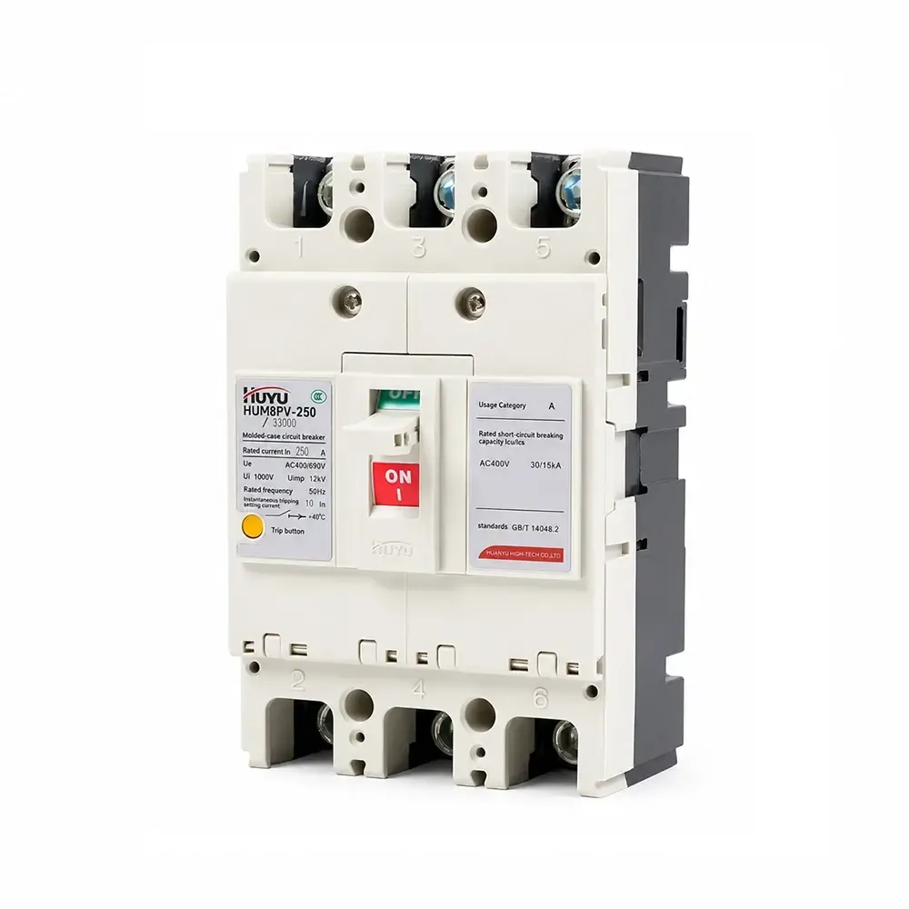
HUM8PV Pemutus Sirkuit Kasus Moulded Fotovoltaik
Seri HUM8PV adalah pemutus sirkuit case molded fotovoltaik yang diberi peringkat 16A–690A pada DC 1000V. Menyediakan perlindungan delay waktu panjang overload dan perlindungan instan hubung singkat. Tersedia dalam 3P dan 4P dengan berbagai aksesori (shunt release, kontak bantu/alarma, mekanisme motor). Memenuhi standar IEC 60947-2. Untuk sistem PV surya, kotak penggabung, dan distribusi DC.
Standar: IEC 60947-2
Arus Terukur: 16A – 690A (frame 125/250/400/630)
Tegangan Terukur: DC 1000V
Pola: 3P, 4P
Kapasitas Pemutusan (Icu/Ics): Hingga 65kA / 50kA (DC750V)
Aplikasi: Sistem PV surya, kotak penggabung, distribusi DC, perlindungan inverter
Informasi Produk
Aplikasi
Pemutus sirkuit case molded fotovoltaik HUM8PV (selanjutnya disebut pemutus sirkuit) diterapkan pada sirkuit DC dengan tegangan nominal hingga DC1000 V, dan arus nominal 16A hingga 690A. Dilengkapi dengan fungsi perlindungan delay waktu panjang overload dan perlindungan instan hubung singkat, produk ini dapat mendistribusikan daya listrik, dan melindungi jalur serta peralatan dari kerusakan akibat overload, hubung singkat, dan kegagalan lainnya. Produk ini sesuai dengan standar IEC60947-2.
Kondisi operasi normal
Suhu lingkungan: -25°C~+70°C; suhu rata-rata dalam 24 jam: ≤+35°C
Ketinggian: ≤ 2000m
Kelembaban: Kelembaban relatif udara pada suhu tertinggi +40°C tidak boleh melebihi 50%; Pada suhu terendah dengan kelembaban relatif lebih tinggi, suhu rata-rata bulan terbasah tidak boleh melebihi +25°C, dan kelembaban relatif rata-rata tidak boleh melebihi 90%;
Tingkat polusi: kelas 3
Dipasang di tempat tanpa risiko ledakan, tanpa gas yang dapat mengkorosi logam atau gas yang dapat merusak isolasi, dan dengan debu konduktif yang sedikit
Kategori pemasangan: III
Model dan arti
Model dan arti
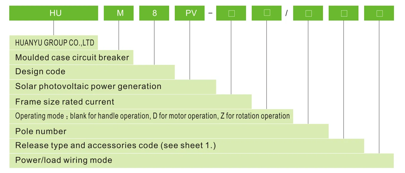
Tipe pelepasan dan kode aksesori
| OF, SD, MX+OF, MN, MV, MVMN, MNs nama |
Tidak aksesori |
Alarm kontak |
Shunt pelepasan |
Bantu kontak |
Pelepasan shunt dan bantu kontak |
Dua kelompok kontak bantu kontak |
Pelepasan shunt dan alarm kontak |
Bantu kontak dan kontak alarm |
Pelepasan shunt, kontak bantu dan kontak alarm |
Dua kelompok kontak bantu, kontak, kontak alarm |
| Tipe pelepasan arus lebih | Kode | |||||||||
| Pelepasan instan | 200 | 208 | 210 | 220 | 240 | 260 | 218 | 228 | 248 | 268 |
| Pelepasan ganda | 300 | 308 | 310 | 320 | 340 | 360 | 318 | 328 | 348 | 368 |
| Catatan: Sesuai dengan mode pengkabelan daya/beban, tipe E,F untuk 3P; tipe G,H,I untuk 4P | ||||||||||
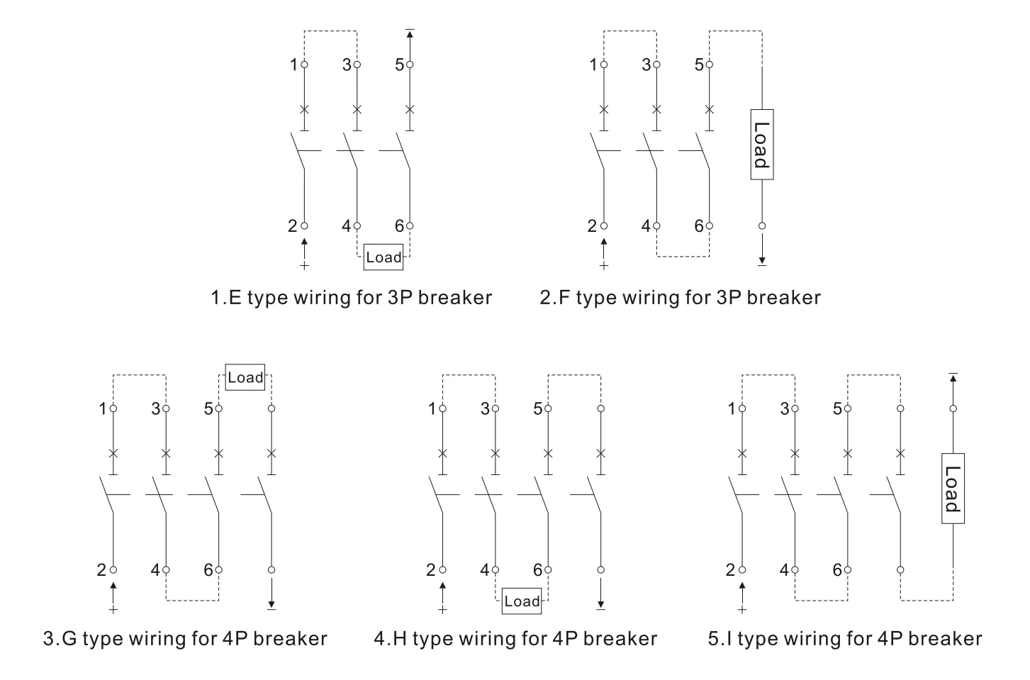
Sistem daya untuk mode pengkabelan di atas silakan cek lembar 2.
| Sistem isolasi ke tanah | Sistem pentanahan negatif | Sistem pentanahan titik netral | |
| DC500V | E | E, F | – |
| DC750V | E、H | F、G、I | H |
| DC1000V | H | 1 | H |
Parameter teknis utama
| Ukuran rangka arus terukur | 125 | 250 | 400 | 630 | |||||
| Arus terukur In(A) | €�20、25、32、40、50、63、80、100、125 | €�125、160、180、200、225、250 | €�250、315、350、400 | €�500、630 | |||||
| Jumlah kutub | 3 | 4 | 3 | 4 | 3 | 4 | 3 | 4 | |
| Tegangan isolasi terukur Ui(V) | 1000 | ||||||||
| Tegangan tahan impuls terukur Uimp(V) | 8000 | ||||||||
| Tegangan kerja terukur Ue(V) | DC 500 DC750 |
DC750 DC 1000 |
DC 500 DC750 |
DC750 DC 1000 |
DC 500 DC750 |
DC750 DC 1000 |
DC 500 DC750 |
DC750 DC 1000 |
|
| Kategori penggunaan | A | ||||||||
| Batas/layanan terukur hubung singkat kapasitas pemutusan Icu/lcs(kA) |
DC500 | 15/15 | 65/65 | 65/65 | 65/65 | ||||
| DC750 | 5/5 | 15/15 | 40/20 | 50/50 | 40/20 | 50/50 | 40/20 | 50/50 | |
| DC1000 | 5/5 | 40/20 | 40/20 | 40/20 | |||||
| Jarak loncatan busur(mm) | ≤50 | ≤50 | ≤100 | ≤100 | |||||
| Operasi performa (kali) |
Terenergikan | 5000 | 5000 | 1000 | 1000 | ||||
| Tidak terenergikan | 10000 | 10000 | 5000 | 5000 | |||||
Kurva karakteristik proteksi
Kurva karakteristik proteksi suhu arus HUM8PV-125
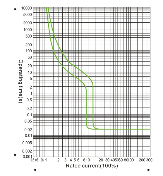
Kurva karakteristik proteksi suhu arus HUM8PV-250
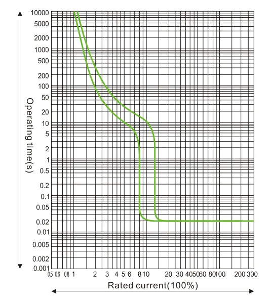
Kurva karakteristik proteksi suhu arus HUM8PV-400
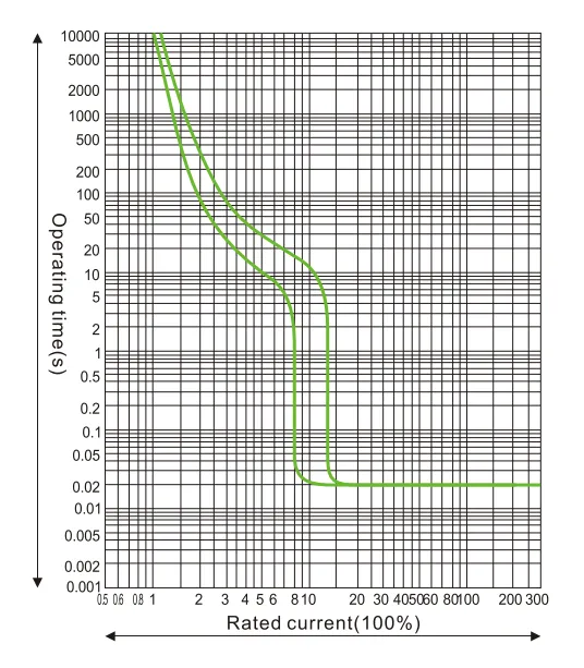
Kurva karakteristik proteksi suhu arus HUM8PV-690
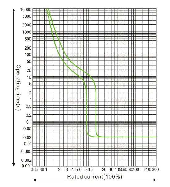
Koefisien pengurangan kapasitas suhu pada suhu berbeda.
| 10℃ | 20℃ | 30℃ | 40℃ | 50℃ | 60℃ | 70℃ | |
| HUM8PV-125 | 15In | 11In | 15In | 1In | 93In | 85In | 8In |
| HUM8PV-250 | 15In | 11In | 15In | 1In | 93In | 85In | 79In |
| HUM8PV-400 | 16ln | 11In | 15In | 1In | 94In | 86ln | 81In |
| HUM8PV-630 | 17In | 11In | 15In | 1In | 9In | 8In | 7In |
Koefisien kapasitas pengurangan di ketinggian tinggi: ketika ketinggian melebihi 2000m, pemutus sirkuit harus disesuaikan seperti pada lembar 4
| Ketinggian (m) | 2000 | 3000 | 4000 | 5000 |
| Tegangan tahan frekuensi daya | 3000 | 2500 | 2000 | 1800 |
| Koefisien penyesuaian arus kerja | 1 | 0.94 | 0.88 | 0.83 |
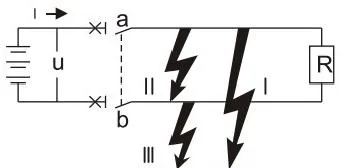
Aplikasi sistem DC: aspek berikut harus dipertimbangkan sebelum memilih breaker dalam sistem DC.
a. tegangan operasi terukur, mempertimbangkan jumlah kutub bertingkat
b. arus terukur, mempertimbangkan daya beban
c. kapasitas pemutusan, mempertimbangkan arus hubung singkat maksimum di lokasi pemasangan
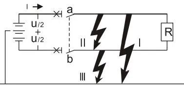
d. mode sistem pentanahan, lihat lembar 5
| Tipe sistem | Sistem pentanahan | Sistem tanpa pentanahan | ||
| Semua jenis tipe gangguan | 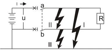 |
 |
 |
|
| Efek kegagalan | Kegagalan I | Menghasilkan arus hubung singkat maksimum Kontak yang terhubung ke kutub positif putus |
Tegangan U/2 menghasilkan arus hubung singkat maksimum Kontak yang terhubung ke kutub negatif putus |
Tidak ada efek |
| Kegagalan II | Menghasilkan arus hubung singkat maksimum Semua kontak bertingkat putus |
Menghasilkan arus hubung singkat maksimum Semua kontak bertingkat putus |
Menghasilkan arus hubung singkat maksimum Semua kontak bertingkat putus |
|
| Kegagalan I | Tidak ada efek | Sama seperti kegagalan I Namun hanya untuk kontak yang terhubung ke kutub negatif |
Tidak ada efek | |
| Situasi terburuk | Kegagalan I | Kegagalan I dan Kegagalan II | Kegagalan II | |
| Situasi pemutusan | Bertingkat di kutub positif dan putus bersama | Untuk setiap kutub, putuskan arus hubung singkat maksimum saat U/2 | Dua kutub putus bersama | |
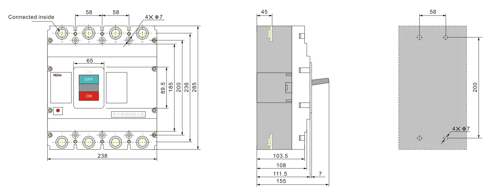
Ukuran keseluruhan dan pemasangan
Wiring tipe E untuk 3P HUM8PV-125 (koneksi depan)
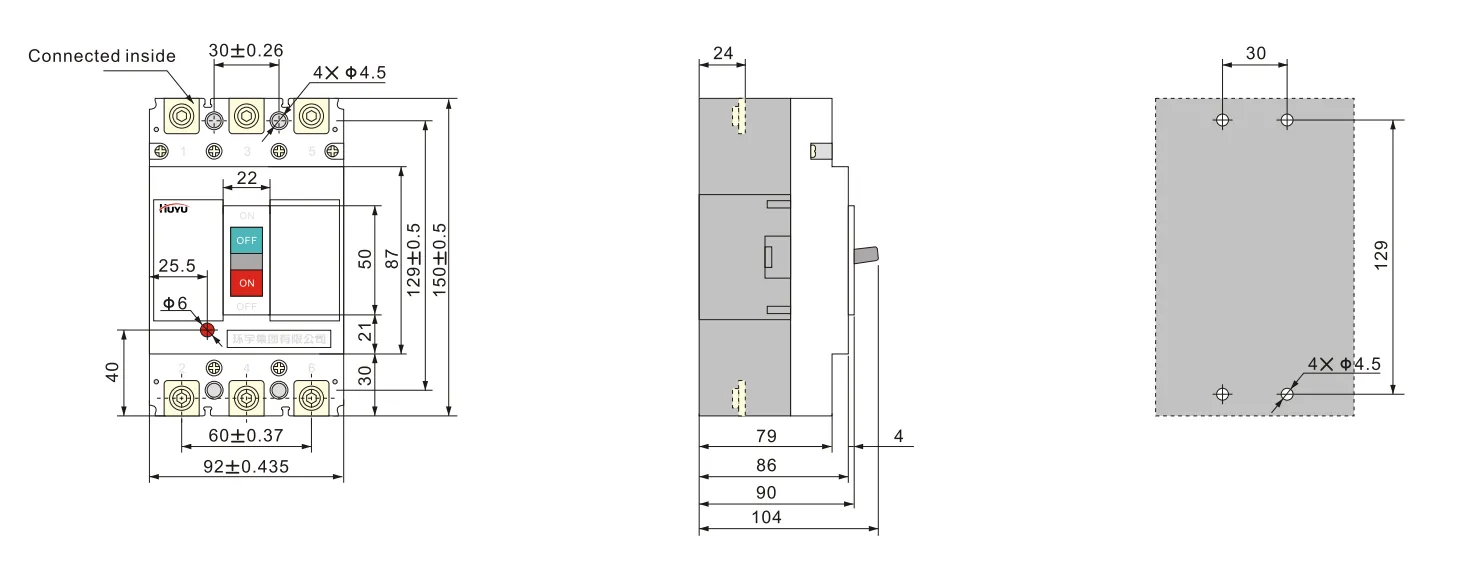
Wiring tipe H untuk 4P HUM8PV-125 (koneksi depan)
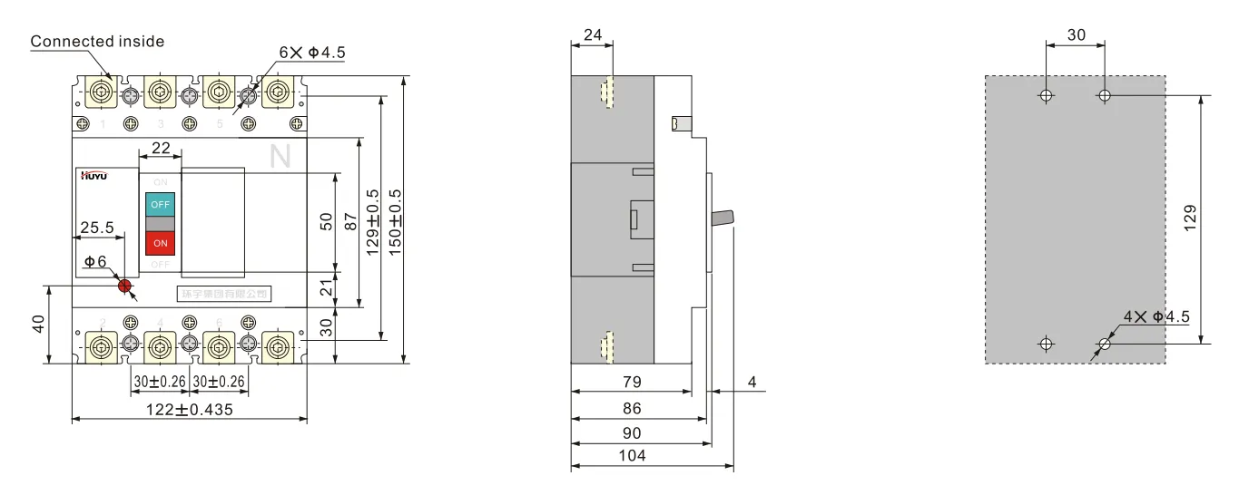
Wiring tipe E untuk 3P HUM8PV-250 (koneksi depan)
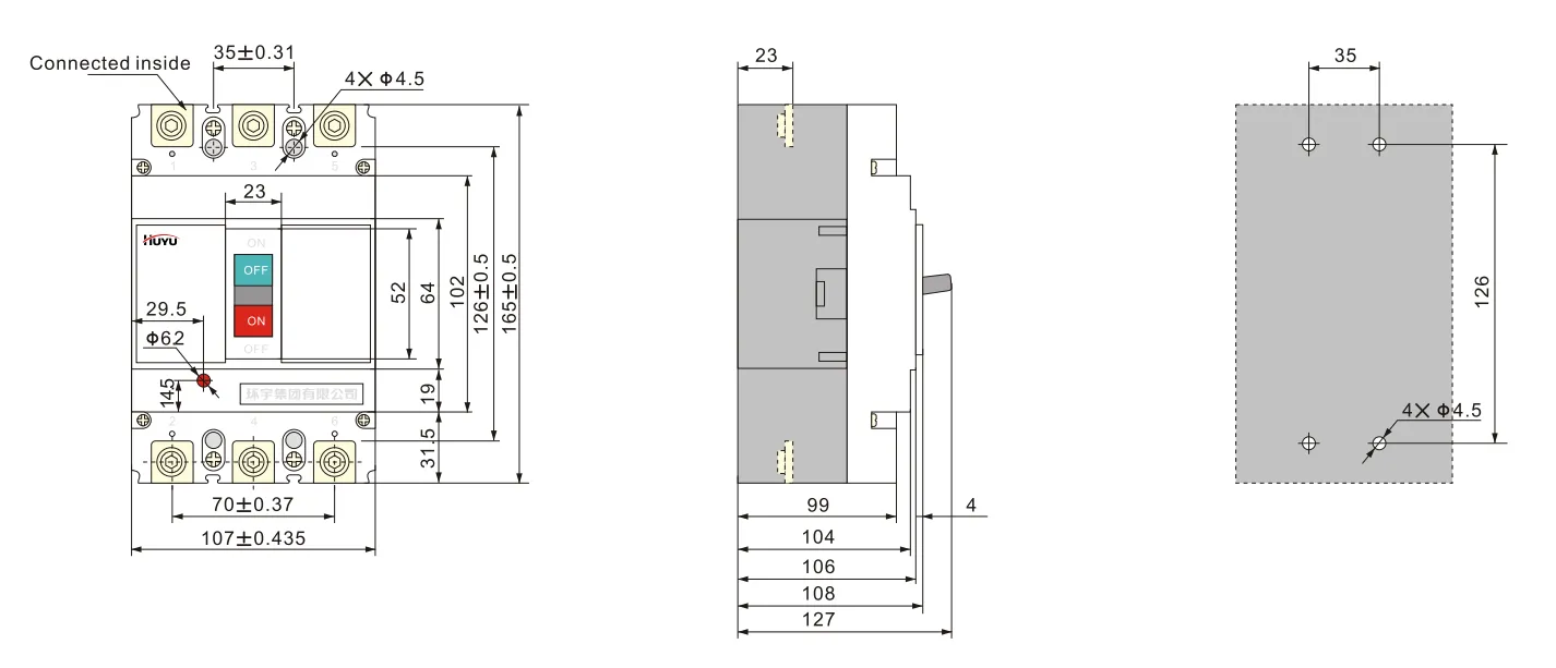
Wiring tipe H untuk 4P HUM8PV-250 (koneksi depan)
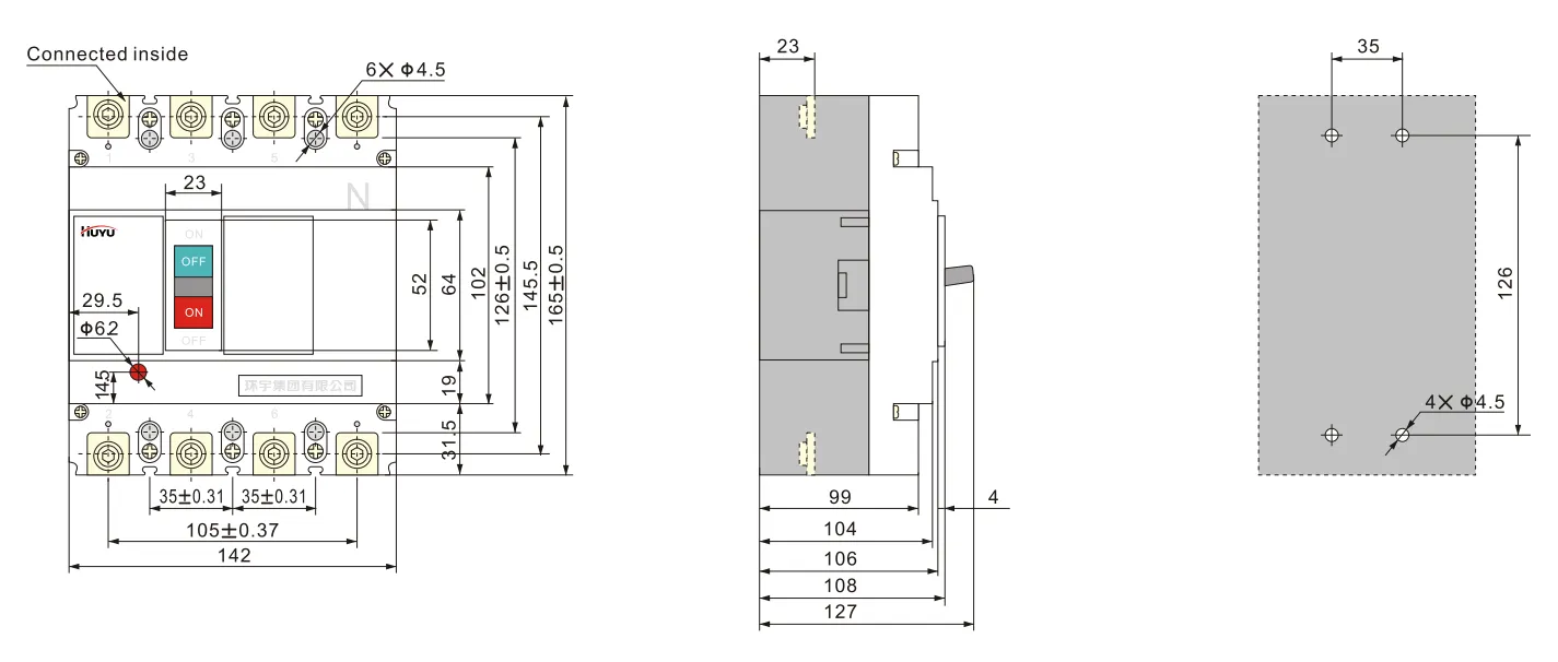
Wiring tipe E untuk 3P HUM8PV-400 (koneksi depan)
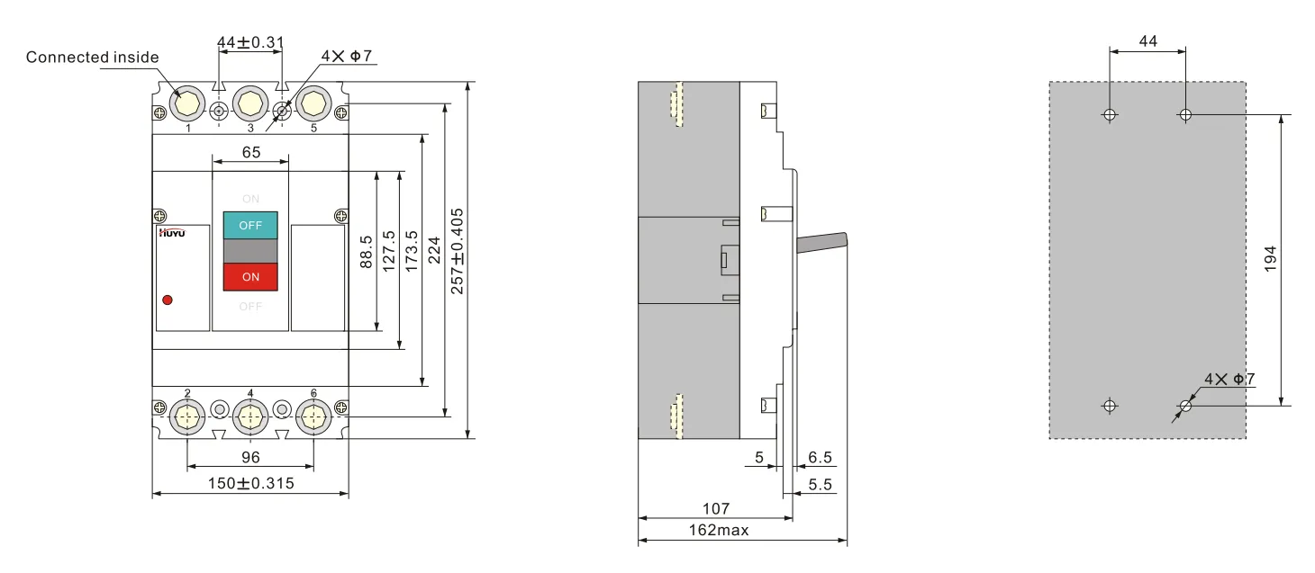
Pengkabelan tipe H untuk 4P HUM8PV-400 (koneksi depan)
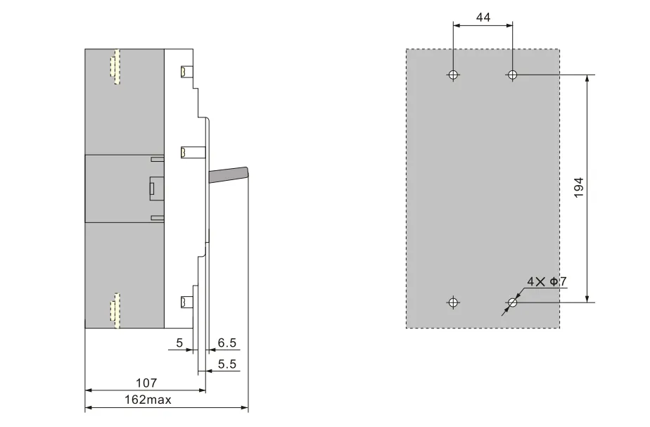
Pengkabelan tipe E untuk 3P HUM8PV-630 (koneksi depan)
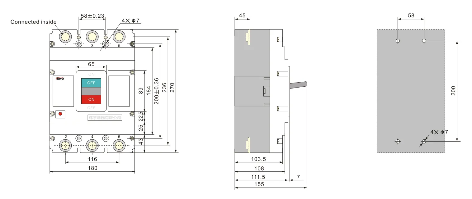
Pengkabelan tipe H untuk 4P HUM8PV-630 (koneksi depan)
Aksesori
Aksesori dapat disediakan sesuai dengan kebutuhan pengguna.
Parameter pelepas shunt:
Tegangan terukur Us: AC230V, 400V; DC 220-250V, 24-30V
Pemutus dapat memutus dengan andal pada (70%-110%) Us, dan waktu aksi adalah 10ms-30ms.
Catatan: saat menggunakan pelepas shunt DC24V-30V, panjang maksimum kabel tembaga harus memenuhi persyaratan lembar 6
| Tegangan daya kontrol terukur Us (DC24V~30V) |
Daya input | Panjang maksimum kabel tembaga | |
| 5mm² | 5mm² | ||
| 100% Us | 50W | 150m | 250m |
| 85% Us | 50W | 100m | 160m |
Nilai terukur kontak bantu dan kontak alarm:
Arus termal konvensional Ith=3A; arus kerja terukur Ie=0.79A (AC230V); Ie=0.47A (AC400V); Ie=0.15A (DC250V)
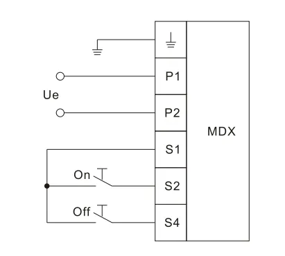
Parameter mekanisme operasi motor lihat lembar 7, tinggi total mekanisme operasi motor lihat lembar 8. Berikut adalah diagram pengkabelan mekanisme operasi motor
| Ukuran rangka arus terukur Ie (A) | Tegangan kerja terukur Ue(V) | Arus awal (A) | Waktu aksi (s) | Frekuensi operasi terukur (kali/jam) | Umur mekanis (kali) |
| 125 | AC 110V~230V 50Hz DC 110V~220V |
≤0.5 | ≤0.8 | 180 | 9000 |
| 250 | |||||
| 400 | ≤2 | 120 | 5000 | ||
| 630 | 3000 |
Kapasitas daya mekanisme operasi motor harus cukup besar untuk memastikan tegangan yang dipengaruhi pada arus awal tidak kurang dari 85% Ue
| EXCB1-DC2-1 | HUM8PV-125 | HUM8PV-250 | HUM8PV-400 | HUM8PV-630 |
| Tinggi | 170 | 199 | 230 | 246 |
Diagram pengkabelan mekanisme operasi motor
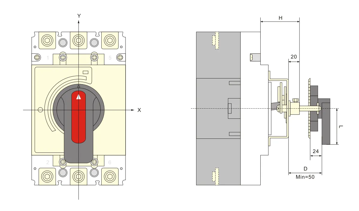
Ukuran pemasangan mekanisme operasi pegangan putar lihat lembar 9
| EXCB1-DC2-1 | HUM8PV-125 | HUM8PV-250 | HUM8PV-400 | HUM8PV-630 |
| Ukuran pemasangan (H) | 54 | 54 | 76 | 83 |
Gambar keseluruhan dan lubang pemasangan pegangan tipe A (persegi)
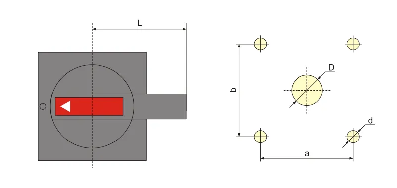
| Model dan spesifikasi | A1 | A2 |
| D | Tengah 42 | φ 63 |
| d | Tengah 4.5 | φ5.5 |
| a | 65 | 88 |
| b | 65 | 88 |
| L | 60 | 140 |
Overall and mounting hole drawing of B type(round)handle
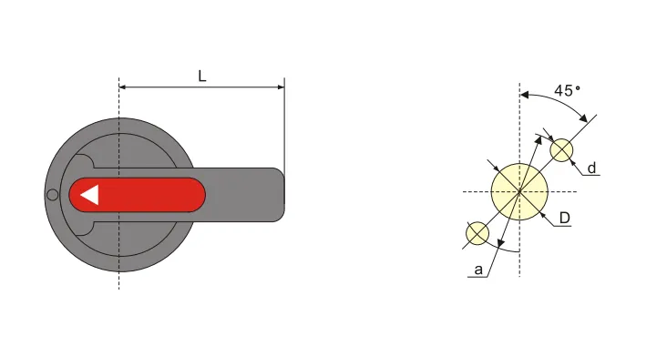
| Model dan spesifikasi | B1 | B2 | B3 |
| D | φ33 | φ33 | 中33 |
| d | Tengah 4.5 | φ4.5 | Tengah 4.5 |
| a | φ 53 | φ53 | φ53 |
| L | 65 | 125 | 95 |
Overall and mounting sizes of centralized rotating handle operation mechanism
8.Installation and maintenance
1.Matters need attention before installation:
a.Appearance shall be well and no-loaded action normal; rated value of breaker and accessories should conform to working conditions at mounting site;no obvious shock at mounting site and conform to normal working conditions
b. Insulation test should be taken before ex-factory. Use 1000VDCMo meter to do retest before installation, among poles of circuit breaker,the insulating resistance between the same pole entering and outlet terminal should be no less than 20MΩ at breaking state
2.Cross section area of conductors should exceed the size regulated in sheet10,and the connection bolt should be screwed up.
3.Characteristic of breaker and accessories should meet our order requirements.
4.The breaker handle can turn to“on”,“off”,“trip”position, when it’s “trip”,the handle rotated to “off” direction,then it can do“on”operation.
5.Before add the internal accessories, the breaker tripper should be switch off.
| Rated current(A) | 10 | 16、20 | 25 | 32 | 40、50 | 63 | 80 | 100 | 125 | 160 | 180、200、225 | 250 | 315、350 | 400 |
| Line cross section area | 1.5 | 2.5 | 4 | 6 | 10 | 16 | 25 | 35 | 50 | 70 | 95 | 120 | 185 | 240 |
| Rated current (A) |
Cable cross section area | Copper bar size | ||
| Kuantitas | Cross section area(mm²) | Kuantitas | Size(mm×mm) | |
| 500 | 2 | 150 | 2 | 30×5 |
| 630 | 2 | 185 | 2 | 40×5 |
9.Ordering information
1.Product name and model
2. Rated current, release type,instantaneous release setting current multiple
3.Accessories name and specification
FAQ
What is a moulded case circuit breaker?
A moulded case circuit breaker (MCCB) is a protective device enclosed in a moulded housing. It provides overcurrent and short-circuit protection for electrical circuits, with adjustable trip settings and higher breaking capacities than miniature circuit breakers.
What is a photovoltaic circuit breaker?
A photovoltaic circuit breaker is specifically designed for DC solar applications. It handles the unique characteristics of PV systems — higher DC voltages (up to 1000V or 1500V DC), non-zero-crossing DC arc extinction, and continuous load variations from solar irradiance.
What is the difference between a circuit breaker and a molded case breaker?
A “circuit breaker” is a general term for any automatic overcurrent protection device. A “molded case circuit breaker” (MCCB) is a specific type — housed in a moulded insulating casing, with higher current ratings (up to several thousand amps), adjustable trip settings, and higher breaking capacities than miniature circuit breakers (MCBs).
Which is better, ACB or MCCB?
Neither is universally “better” — they serve different applications. ACB (Air Circuit Breaker) is used for low-voltage main distribution (high current, up to 6300A), with adjustable protection and high breaking capacity. MCCB (Moulded Case Circuit Breaker) is used for branch circuit protection (up to 1600A), more compact and cost-effective for feeder circuits. Choose based on application current rating and protection requirements.