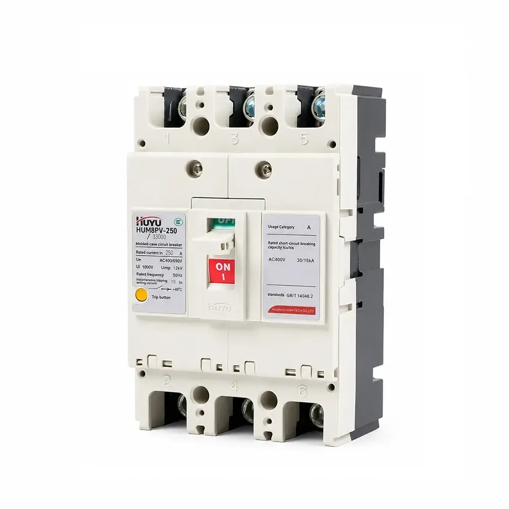
HUM8PV Photovoltaic Moulded Case Circuit Breaker
The HUM8PV series is a photovoltaic molded case circuit breaker rated 16A–690A at DC 1000V. Provides overload long-time delay and short-circuit instantaneous protection. Available in 3P and 4P with multiple accessories (shunt release, auxiliary/alarm contacts, motor mechanism). Complies with IEC 60947-2. For solar PV systems, combiner boxes, and DC distribution.
Standard: IEC 60947-2
Rated Current: 16A – 690A (125/250/400/630 frame)
Rated Voltage: DC 1000V
Poles: 3P, 4P
Breaking Capacity (Icu/Ics): Up to 65kA / 50kA (DC750V)
Applications: Solar PV systems, combiner boxes, DC distribution, inverter protection
Product Information
1.Application
HUM8PV photovoltaic moulded case circuit breaker(hereinafter referred to as circuit breaker) isapplied to the DC circuit with rated voltage up to DC1000 V, and rated current 16A to 690A.Featured with functions of overload long time delay protection and short circuit instantaneousprotection, the product can distribute electric power,and protect the line and the equipmentfrom being damaged due to overload, short circuit, and other failures.This product accords with the standard of IEC60947-2.
2.Normal operation conditions
1.Ambient temperature:-25°C~+70°C;average temperaturewithin24h:≤+35°C
2. Altitude: $ \leqslant $ 2000m
3. Humidity: The air relative humidity under the highest temperature +40C cannot surpass 50%;Under the lowest temperature has a higher relative humidity, the wettest month’s averagelowest temperature cannot surpass +25C, and the average relative humidity cannotexceed 90%;
4.Pollution degree:class3
5. Mounted at places without explosive risk,without gases that may be corrosive to metal orgases that may cause damage to the insulation, and with little conducting dust
6.Mounting category:III
3.Model and meaningl
1.Model and meaning
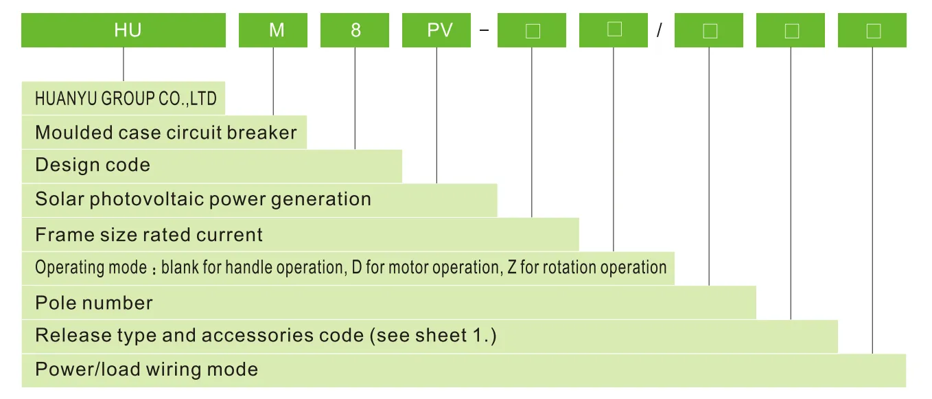
Release type and accessories code
| Accessories name |
No accessories |
Alarm contact |
Shunt release |
Auxiliary contact |
Shunt release and auxiliary contact |
Two groups of auxiliary contacts |
Shunt release and alarm contact |
Auxiliary contact and alarm contact |
Shunt release, auxiliary contact and alarm contact |
Two groups of auxiliary contacts, alarm contact |
| Over current release type | Code | |||||||||
| Instantaneous release | 200 | 208 | 210 | 220 | 240 | 260 | 218 | 228 | 248 | 268 |
| Duplex release | 300 | 308 | 310 | 320 | 340 | 360 | 318 | 328 | 348 | 368 |
| Note:As per power/load wiring mode,E,F type for 3P;G,H,I type for 4P | ||||||||||
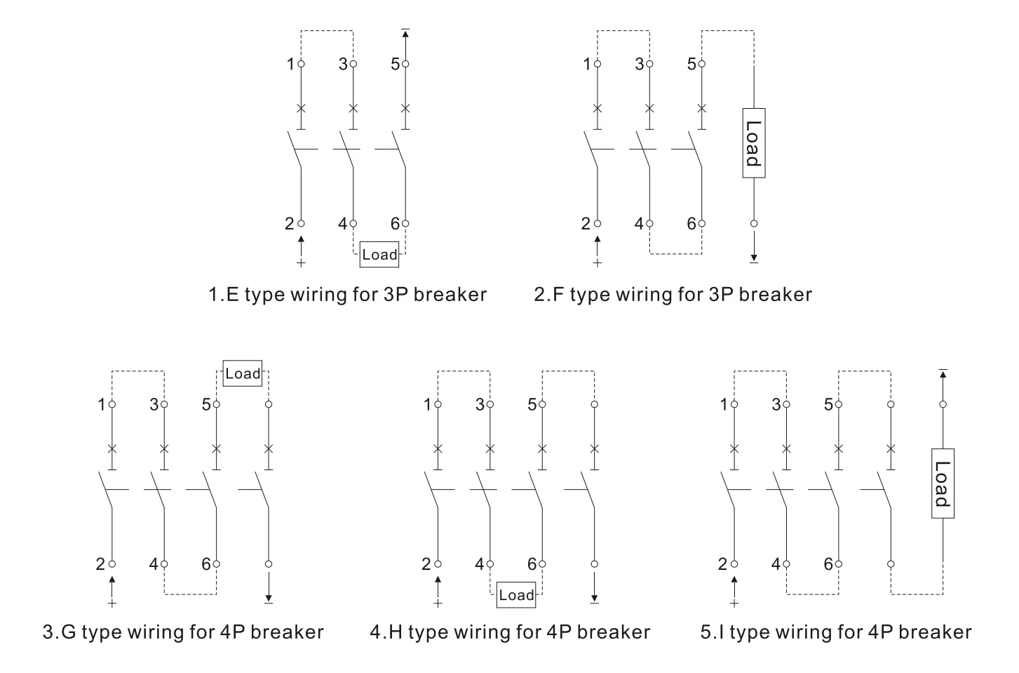
Power systems for above wiring mode please check sheet 2.
| To earth insulation system | Negative grounding system | Neutral point grounding system | |
| DC500V | E | E、F | – |
| DC750V | E、H | F、G、I | H |
| DC1000V | H | 1 | H |
4.Main technical parameters
| Frame size rated current | 125 | 250 | 400 | 630 | |||||
| Rated current In(A) | 16、20、25、32、40、50、63、80、100、125 | 100、125、160、180、200、225、250 | 225、250、315、350、400 | 400、500、630 | |||||
| Pole number | 3 | 4 | 3 | 4 | 3 | 4 | 3 | 4 | |
| Rated insulation voltage Ui(V) | 1000 | ||||||||
| Rated impulse withstand voltage Uimp(V) | 8000 | ||||||||
| Rated working voltage Ue(V) | DC 500 DC750 |
DC750 DC 1000 |
DC 500 DC750 |
DC750 DC 1000 |
DC 500 DC750 |
DC750 DC 1000 |
DC 500 DC750 |
DC750 DC 1000 |
|
| Using category | A | ||||||||
| Rated limit/service short circuit breaking capacity Icu/lcs(kA) |
DC500 | 15/15 | 65/65 | 65/65 | 65/65 | ||||
| DC750 | 5/5 | 15/15 | 40/20 | 50/50 | 40/20 | 50/50 | 40/20 | 50/50 | |
| DC1000 | 5/5 | 40/20 | 40/20 | 40/20 | |||||
| Flashover distance(mm) | ≤50 | ≤50 | ≤100 | ≤100 | |||||
| Operation performance (times) |
Energized | 5000 | 5000 | 1000 | 1000 | ||||
| Non-energized | 10000 | 10000 | 5000 | 5000 | |||||
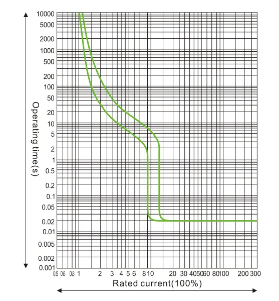
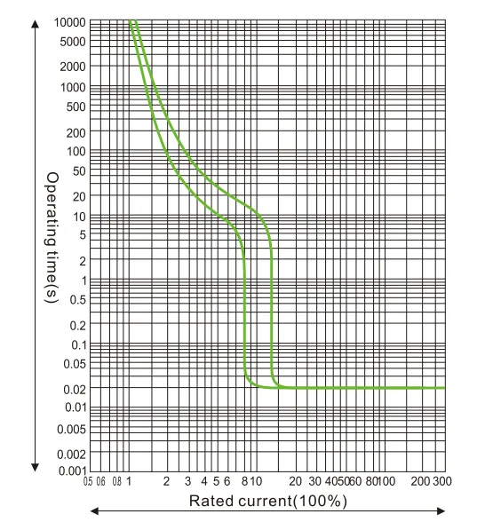
5.Protection characteristics curve
1.HUM8PV-125 current temperature protection characteristics curve
2.HUM8PV-250 current temperature protection characteristics curve
3.HUM8PV-400 current temperature protection characteristics curve
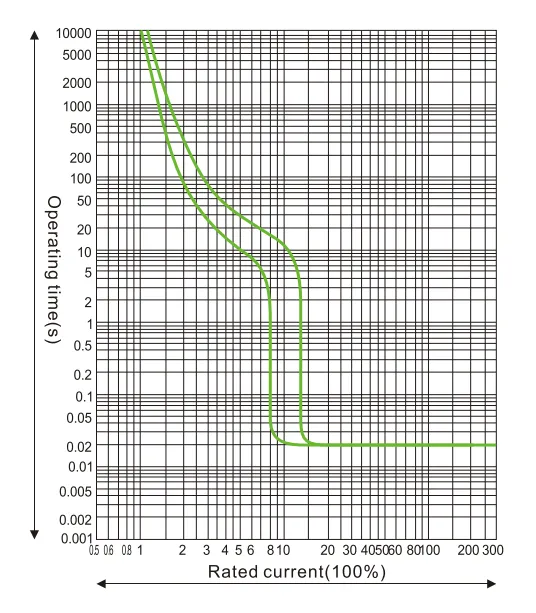
4.HUM8PV-690 current temperature protection characteristics curve
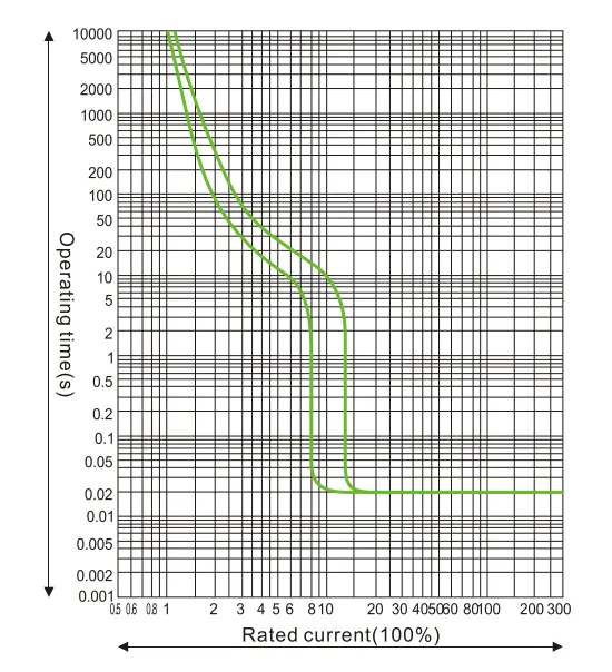
5. The temperature reducing capacity coefficient at different temperature.
| 10℃ | 20℃ | 30℃ | 40℃ | 50℃ | 60℃ | 70℃ | |
| HUM8PV-125 | 1.15In | 1.11In | 1.15In | 1In | 0.93In | 0.85In | 0.8In |
| HUM8PV-250 | 1.15In | 1.11In | 1.15In | 1In | 0.93In | 0.85In | 0.79In |
| HUM8PV-400 | 1.16ln | 1.11In | 1.15In | 1In | 0.94In | 0.86ln | 0.81In |
| HUM8PV-630 | 1.17In | 1.11In | 1.15In | 1In | 0.9In | 0.8In | 0.7In |
6.The reducing capacity coeficient in high altitude:when the altitude exceeds 2000m,the circuit breaker should be adjusted as sheet4
| Altitude(m) | 2000 | 3000 | 4000 | 5000 |
| Power frequency withstand voltage | 3000 | 2500 | 2000 | 1800 |
| Working current adjustment coefficient | 1 | 0.94 | 0.88 | 0.83 |
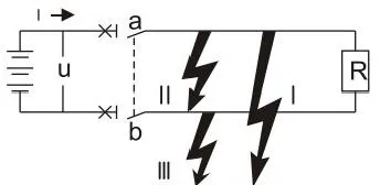
7.DC system application: the following aspects should be considered before choose breaker in DC system.
a.rated operation voltage, considering cascaded pole number
b.rated current, considering load power
c. breaking capacity, considering maximum short circuit current at mounting site
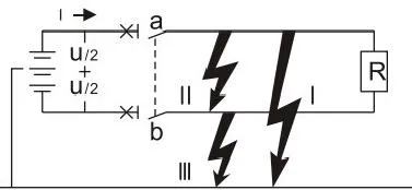
d. Grounding system mode, see sheet 5
| System type | Grounding system | Ungrounding system | ||
| All kinds of fault types | 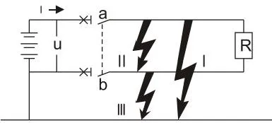 |
 |
 |
|
| Failure effect | Failure l | Generate maximum short circuit current Contact connecting to positive pole break |
U/2 voltage produce maximum short circuit current Contact connecting to negative pole break |
No effect |
| Failure ll | Generate maximum short circuit current All the cascaded contacts break |
Generate maximum short circuit current All the cascaded contacts break |
Generate maximum short circuit current All the cascaded contacts break |
|
| Failure I | No effect | Same as failure l But only for contact connecting to negative pole |
No effect | |
| The worst situation | Failure l | Failure l and Failure ll | Failure ll | |
| Breaking situation | Cascade in positive pole and break together | For each pole,break maximum short circuit current when U/2 | Two poles break together | |
6.Overall and mounting size
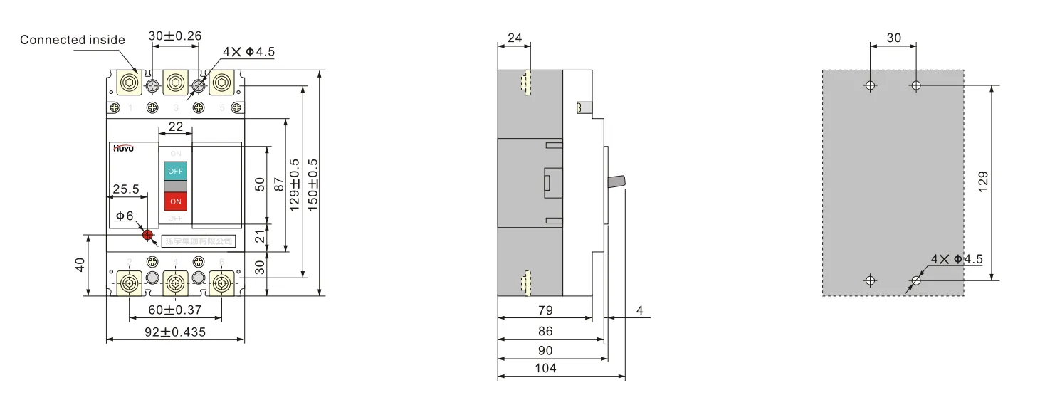
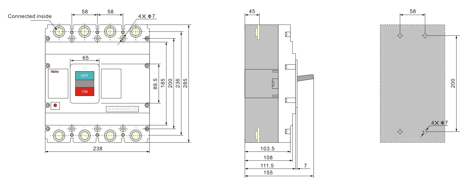
1.E type wiring for 3PHUM8PV-125(front connection)
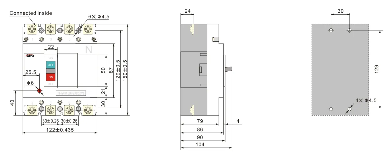
2.H type wiring for 4P HUM8PV-125(front connection)
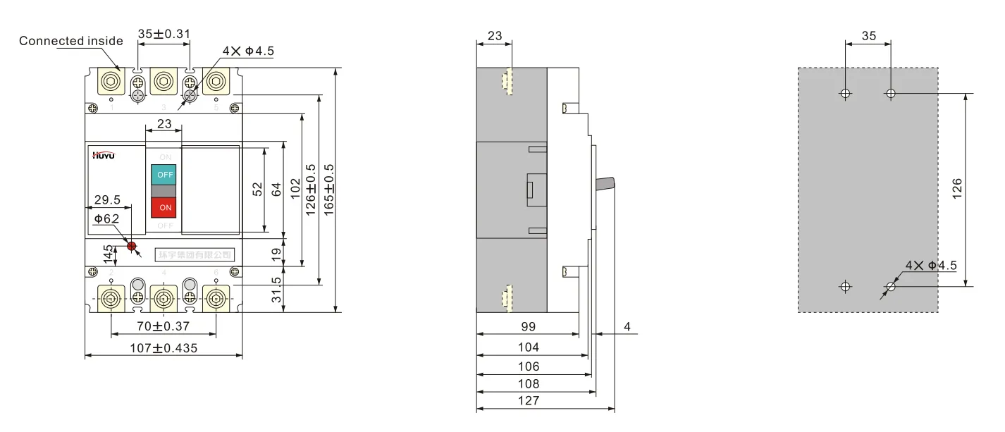
3.E type wiring for 3P HUM8PV-250(front connection)
4.H type wiring for 4PHUM8PV-250(front connection)
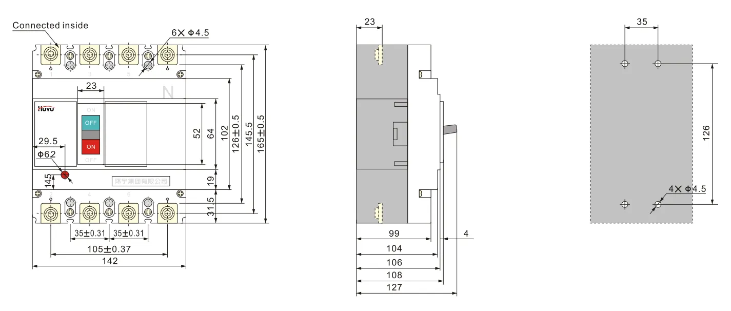
5.E type wiring for 3PHUM8PV-400(front connection)
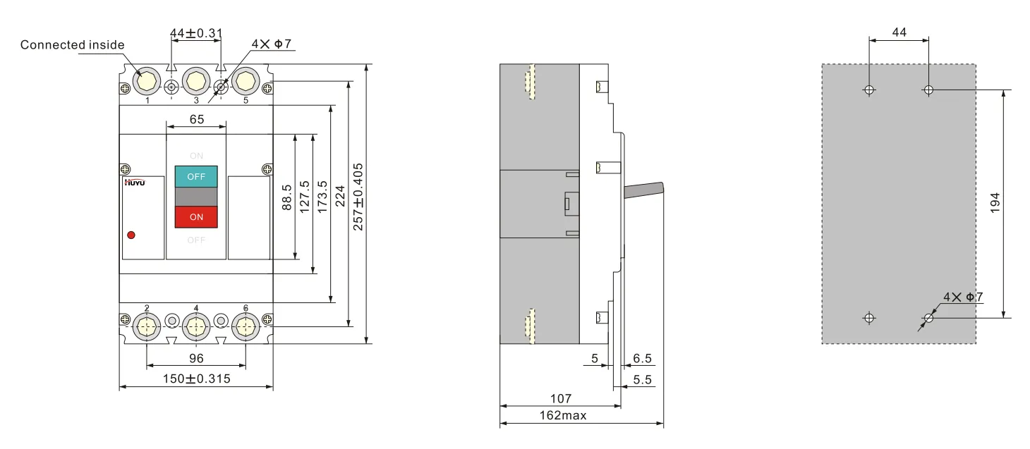
6.H type wiring for 4P HUM8PV-400 (front connection)
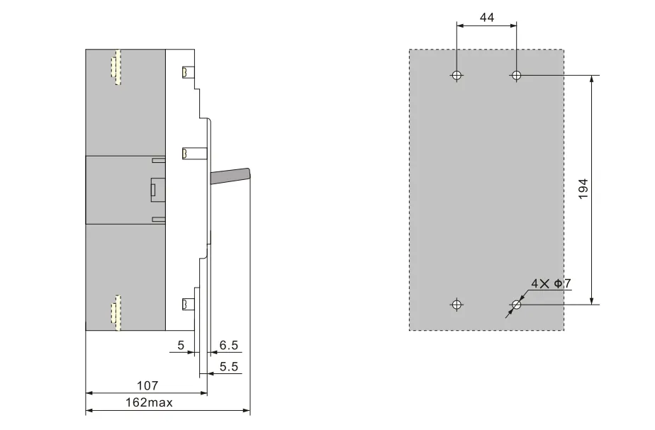
7.E type wiring for 3PHUM8PV-630(front connection)
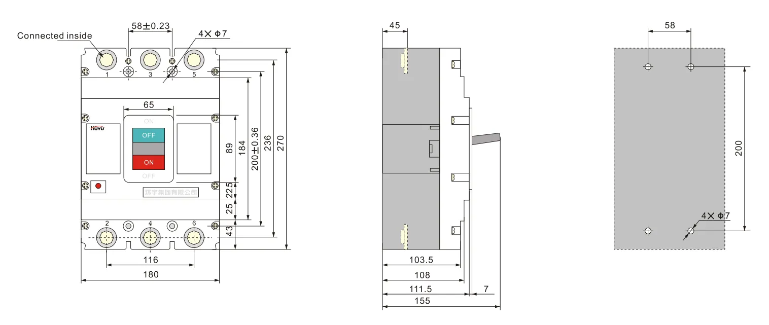
8.H type wiring for 4P HUM8PV-630(front connection)
7.Accessories
1.Accessories can be provided as per user’s requirement.
2.Shunt release parameters:
Rated voltage Us:AC230V,400V;DC 220-250V,24-30V
Breaker can reliably break at(70%-110%)Us, and action time is 10ms-30ms.
Note:when uses DC24V-30V shunt release, the maximum length of copper line should meet the requirements of sheet 6
| Rated control power voltage Us (DC24V~30V) |
Input power | Maximum length of copper line | |
| 1.5mm² | 2.5mm² | ||
| 100%Us | 50W | 150m | 250m |
| 85%Us | 50W | 100m | 160m |
3. Rated value of auxiliary contact and alarm contact:
Conventional thermal current Ith=3A;rated working current le=0.79A(AC230V); le=0.47A(AC400V); le=0.15A(DC250V)
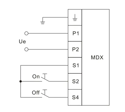
4. Parameters of motor operation mechanism see sheet7, total height of motor operation mechanism see sheet 8. The following isthe wiring diagram of motor operation mechanism
| Frame size rated current le(A) | Rated working voltage Ue(V) | Starting current(A) | Action time(s) | Rated operation frequency(times/h) | Mechanical life (times) |
| 125 | AC 110V~230V 50Hz DC 110V~220V |
≤0.5 | ≤0.8 | 180 | 9000 |
| 250 | |||||
| 400 | ≤2 | 120 | 5000 | ||
| 630 | 3000 |
The power capacity of motor operation mechanism should be large enough to ensure the voltage impacted on at starting current should be no less than 85%Ue
| Model | HUM8PV-125 | HUM8PV-250 | HUM8PV-400 | HUM8PV-630 |
| Height | 170 | 199 | 230 | 246 |
Wiring diagram of motor operation mechanism
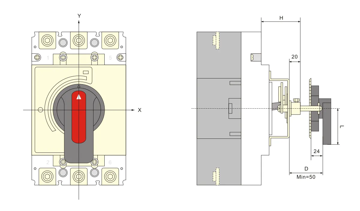
5. Mounting size of rotating handle operation mechanism see sheet 9
| Model | HUM8PV-125 | HUM8PV-250 | HUM8PV-400 | HUM8PV-630 |
| Mounting size(H) | 54 | 54 | 76 | 83 |
Overall and mounting hole drawing of A type(square)handle
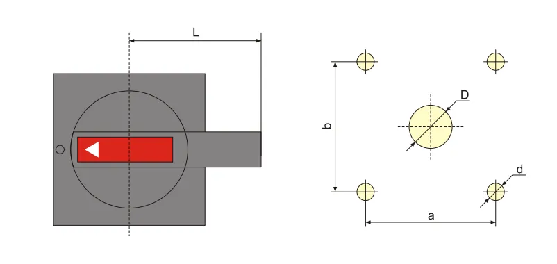
| Model and specification | A1 | A2 |
| D | 中42 | φ 63 |
| d | 中4.5 | φ5.5 |
| a | 65 | 88 |
| b | 65 | 88 |
| L | 60 | 140 |
Overall and mounting hole drawing of B type(round)handle
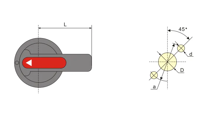
| Model and specification | B1 | B2 | B3 |
| D | φ33 | φ33 | 中33 |
| d | 中4.5 | φ4.5 | 中4.5 |
| a | φ 53 | φ53 | φ53 |
| L | 65 | 125 | 95 |
Overall and mounting sizes of centralized rotating handle operation mechanism
8.Installation and maintenance
1.Matters need attention before installation:
a.Appearance shall be well and no-loaded action normal; rated value of breaker and accessories should conform to working conditions at mounting site;no obvious shock at mounting site and conform to normal working conditions
b. Insulation test should be taken before ex-factory. Use 1000VDCMo meter to do retest before installation, among poles of circuit breaker,the insulating resistance between the same pole entering and outlet terminal should be no less than 20MΩ at breaking state
2.Cross section area of conductors should exceed the size regulated in sheet10,and the connection bolt should be screwed up.
3.Characteristic of breaker and accessories should meet our order requirements.
4.The breaker handle can turn to“on”,“off”,“trip”position, when it’s “trip”,the handle rotated to “off” direction,then it can do“on”operation.
5.Before add the internal accessories, the breaker tripper should be switch off.
| Rated current(A) | 10 | 16、20 | 25 | 32 | 40、50 | 63 | 80 | 100 | 125 | 160 | 180、200、225 | 250 | 315、350 | 400 |
| Line cross section area | 1.5 | 2.5 | 4 | 6 | 10 | 16 | 25 | 35 | 50 | 70 | 95 | 120 | 185 | 240 |
| Rated current (A) |
Cable cross section area | Copper bar size | ||
| Quantity | Cross section area(mm²) | Quantity | Size(mm×mm) | |
| 500 | 2 | 150 | 2 | 30×5 |
| 630 | 2 | 185 | 2 | 40×5 |
9.Ordering information
1.Product name and model
2. Rated current, release type,instantaneous release setting current multiple
3.Accessories name and specification
FAQ
What is a moulded case circuit breaker?
A moulded case circuit breaker (MCCB) is a protective device enclosed in a moulded housing. It provides overcurrent and short-circuit protection for electrical circuits, with adjustable trip settings and higher breaking capacities than miniature circuit breakers.
What is a photovoltaic circuit breaker?
A photovoltaic circuit breaker is specifically designed for DC solar applications. It handles the unique characteristics of PV systems — higher DC voltages (up to 1000V or 1500V DC), non-zero-crossing DC arc extinction, and continuous load variations from solar irradiance.
What is the difference between a circuit breaker and a molded case breaker?
A “circuit breaker” is a general term for any automatic overcurrent protection device. A “molded case circuit breaker” (MCCB) is a specific type — housed in a moulded insulating casing, with higher current ratings (up to several thousand amps), adjustable trip settings, and higher breaking capacities than miniature circuit breakers (MCBs).
Which is better, ACB or MCCB?
Neither is universally “better” — they serve different applications. ACB (Air Circuit Breaker) is used for low-voltage main distribution (high current, up to 6300A), with adjustable protection and high breaking capacity. MCCB (Moulded Case Circuit Breaker) is used for branch circuit protection (up to 1600A), more compact and cost-effective for feeder circuits. Choose based on application current rating and protection requirements.