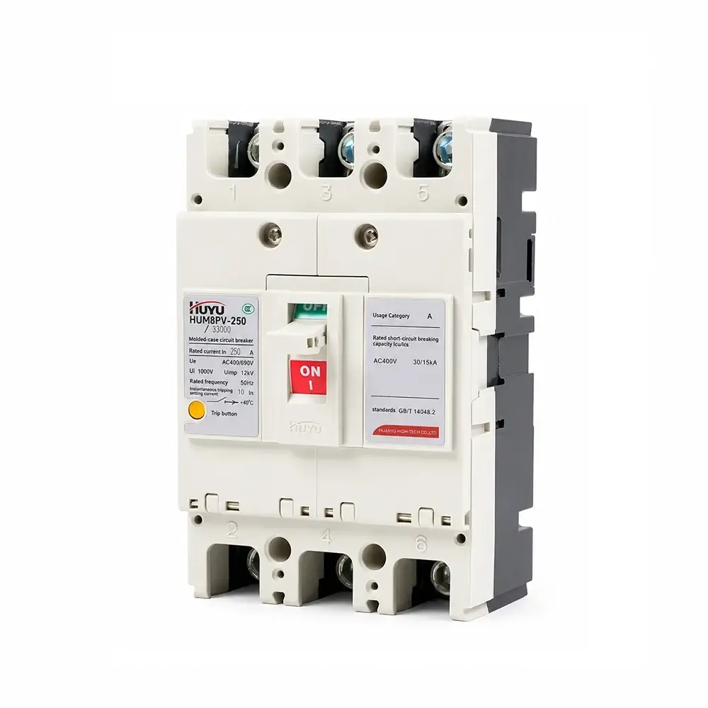
قاطع الدائرة المصنوع من مادة HUM8PV للطاقة الشمسية
سلسلة HUM8PV هي قاطع دائرة مصبوب ضوئيًا مصنف من 16A إلى 690A عند DC 1000V. يوفر حماية من الحمل الزائد بتأخير طويل الأمد وحماية فورية من الدائرة القصيرة. متوفر بـ 3P و 4P مع ملحقات متعددة (إطلاق شنت، جهات اتصال مساعدة/إنذار، آلية محرك). يتوافق مع IEC 60947-2. لأنظمة الطاقة الشمسية، صناديق الجمع، وتوزيع DC.
المعيار: IEC 60947-2
التيار المصنف: 16A – 690A (إطار 125/250/400/630)
الجهد المصنف: تيار مستمر 1000 فولت
الأقطاب: 3P، 4P
قدرة الفصل (Icu/Ics): حتى 65kA / 50kA (DC750V)
التطبيقات: أنظمة الطاقة الشمسية، صناديق الجمع، توزيع DC، حماية العاكس
معلومات المنتج
التطبيق
قاطع الدائرة المصبوب الضوئي HUM8PV (المشار إليه فيما بعد بقاطع الدائرة) يُستخدم في الدائرة DC بجهد مصنف يصل إلى DC1000 V، والتيار المصنف من 16A إلى 690A. يتميز بوظائف حماية الحمل الزائد بتأخير طويل الأمد وحماية فورية من الدائرة القصيرة، يمكن للمنتج توزيع الطاقة الكهربائية، وحماية الخط والمعدات من التلف بسبب الحمل الزائد، الدائرة القصيرة، وغيرها من الأعطال. يتوافق هذا المنتج مع معيار IEC60947-2.
ظروف التشغيل العادية
درجة حرارة البيئة: -25°C ~ +70°C؛ متوسط درجة الحرارة خلال 24 ساعة: ≤ +35°C
الارتفاع: $ ≤ $ 2000m
الرطوبة: لا يمكن أن تتجاوز الرطوبة النسبية للهواء تحت أعلى درجة حرارة +40C 50%؛ تحت أدنى درجة حرارة، إذا كانت الرطوبة النسبية أعلى، لا يمكن أن تتجاوز أدنى درجة حرارة متوسطة في أكثر الشهور رطوبة +25C، ولا يمكن أن تتجاوز الرطوبة النسبية المتوسطة 90%؛;
درجة التلوث: الفئة 3
مثبت في أماكن بدون خطر انفجار، بدون غازات قد تكون مدمرة للمعادن أو غازات قد تسبب ضررًا للعزل، ومع غبار موصل قليل
فئة التركيب: III
النموذج والمعنى
النموذج والمعنى
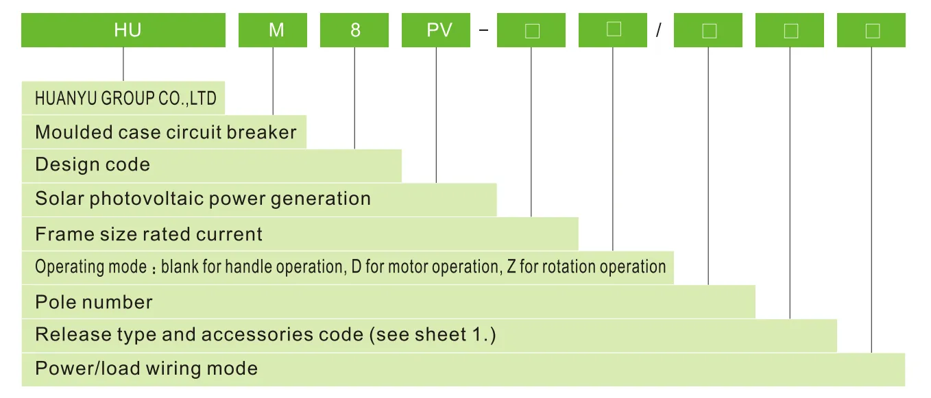
نوع الإطلاق ورمز الملحقات
| الملحقات الاسم |
لا الملحقات |
إنذار جهة الاتصال |
إطلاق شنت مساعد |
إطلاق شنت جهة الاتصال |
وجهات الاتصال المساعدة مجموعتان جهة الاتصال |
من جهات الاتصال المساعدة إطلاق شنت وجهات الاتصال المساعدة |
وجهة الاتصال الإنذارية إطلاق شنت، جهة الاتصال |
إطلاق شنت جهة الاتصال المساعدة وجهة الاتصال الإنذارية |
من جهات الاتصال المساعدة،, نوع إطلاق التيار الزائد الرمز |
من جهات الاتصال المساعدة إطلاق فوري إطلاق مزدوج, وجهة الاتصال الإنذارية |
| نوع تحرير التيار الزائد | رمز | |||||||||
| تحرير فوري | 200 | 208 | 210 | 220 | 240 | 260 | 218 | 228 | 248 | 268 |
| تحرير مزدوج | 300 | 308 | 310 | 320 | 340 | 360 | 318 | 328 | 348 | 368 |
| ملاحظة: حسب وضع توصيل الطاقة/الحمل، النوع E,F للـ 3P؛ النوع G,H,I للـ 4P | ||||||||||
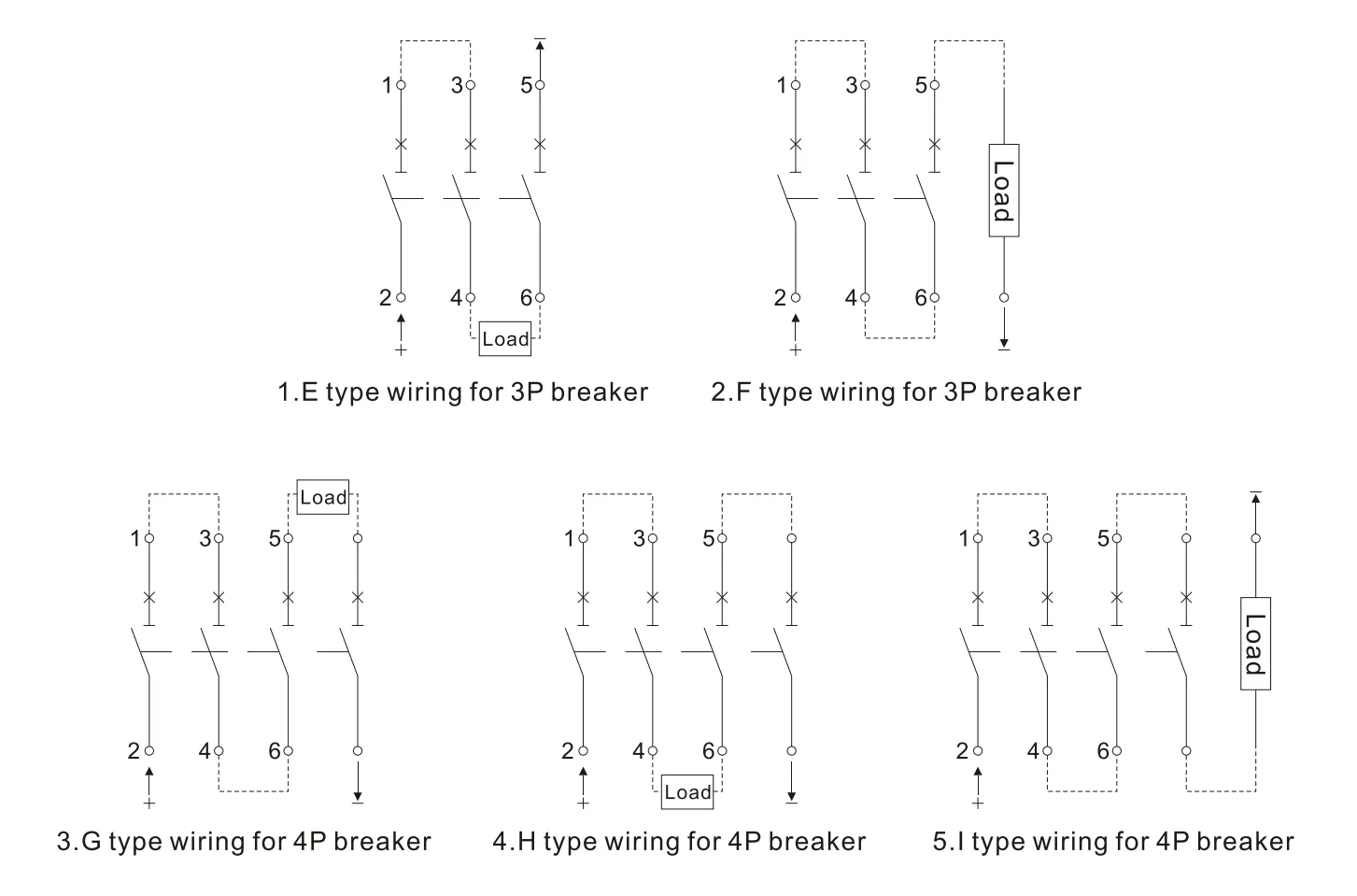
أنظمة الطاقة لوضع التوصيل أعلاه يرجى مراجعة الورقة 2.
| إلى نظام عزل الأرض | نظام التأريض السالب | نظام تأريض نقطة التعادل | |
| DC500 فولت | E | E، F | – |
| DC750 فولت | E، H | F، G، I | H |
| DC1000 فولت | H | 1 | H |
المعلمات الفنية الرئيسية
| حجم الإطار التيار المقنن | 125 | 250 | 400 | 630 | |||||
| التيار المقنن In (A) | 16، 20، 25، 32، 40، 50، 63، 80، 100، 125 | 100، 125، 160، 180، 200، 225، 250 | 225، 250، 315، 350، 400 | 400، 500، 630 | |||||
| عدد الأقطاب | 3 | 4 | 3 | 4 | 3 | 4 | 3 | 4 | |
| جهد العزل المقنن Ui(V) | 1000 | ||||||||
| جهد مقاومة الاندفاع المقنن Uimp (V) | 8000 | ||||||||
| جهد العمل المقنن Ue (V) | دي سي 500 دي سي 750 |
دي سي 750 دي سي 1000 |
دي سي 500 دي سي 750 |
دي سي 750 دي سي 1000 |
دي سي 500 دي سي 750 |
دي سي 750 دي سي 1000 |
دي سي 500 دي سي 750 |
دي سي 750 دي سي 1000 |
|
| فئة الاستخدام | A | ||||||||
| الحد/الخدمة المقننة دائرة القصر قدرة الفصل Icu/lcs (kA) |
دي سي 500 | 15/15 | 65/65 | 65/65 | 65/65 | ||||
| دي سي 750 | 5/5 | 15/15 | 40/20 | 50/50 | 40/20 | 50/50 | 40/20 | 50/50 | |
| دي سي 1000 | 5/5 | 40/20 | 40/20 | 40/20 | |||||
| مسافة التفريغ (مم) | ≤50 | ≤50 | ≤100 | ≤100 | |||||
| التشغيل الأداء (مرات) |
تحت الجهد | 5000 | 5000 | 1000 | 1000 | ||||
| بدون جهد | 10000 | 10000 | 5000 | 5000 | |||||
منحنى خصائص الحماية
منحنى خصائص حماية التيار والحرارة HUM8PV-125
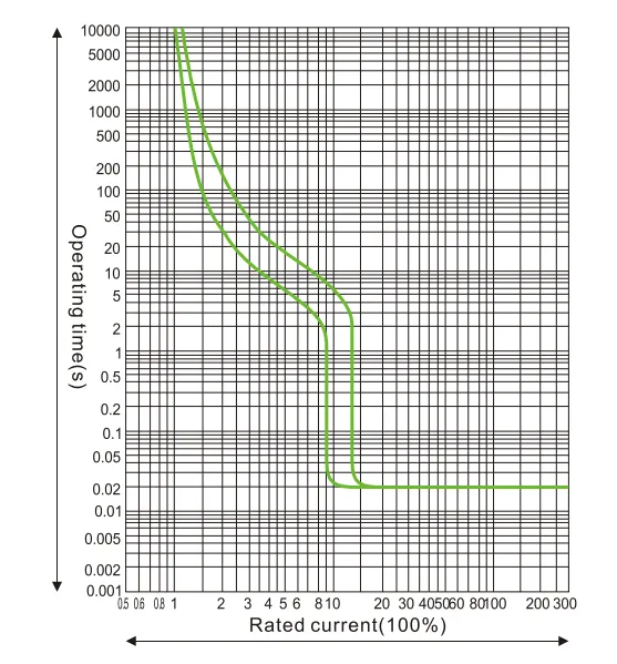
منحنى خصائص حماية التيار والحرارة HUM8PV-250
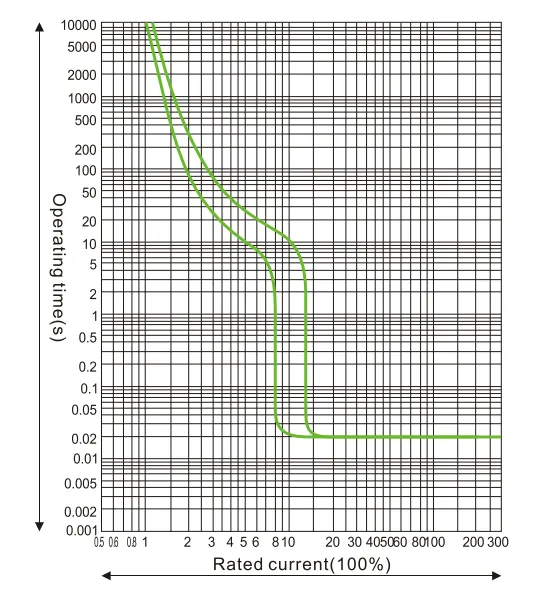
منحنى خصائص حماية التيار والحرارة HUM8PV-400
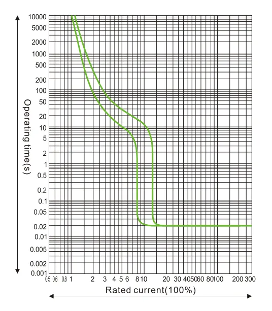
منحنى خصائص حماية التيار والحرارة HUM8PV-690
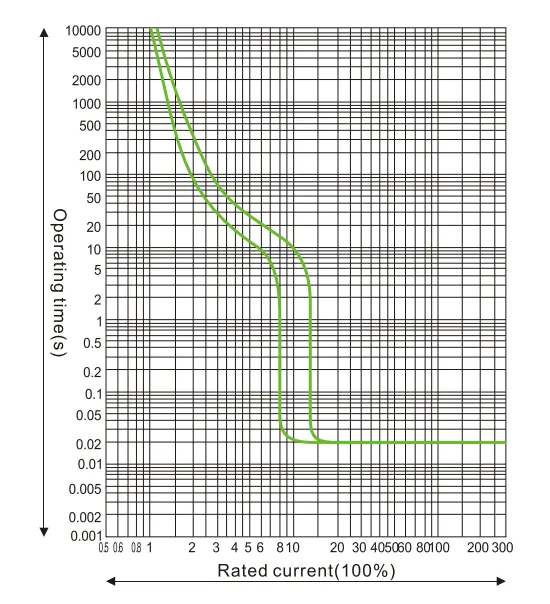
معامل تقليل الحرارة عند درجات حرارة مختلفة.
| 10℃ | 20℃ | 30℃ | 40℃ | 50℃ | 60℃ | 70℃ | |
| HUM8PV-125 | 15In | 11In | 15In | 1في | 93In | 85In | 8In |
| HUM8PV-250 | 15In | 11In | 15In | 1في | 93In | 85In | 79In |
| HUM8PV-400 | 16ln | 11In | 15In | 1في | 94In | 86ln | 81In |
| HUM8PV-630 | 17In | 11In | 15In | 1في | 9In | 8In | 7In |
معامل قدرة التخفيض في الارتفاعات العالية: عندما يتجاوز الارتفاع 2000م، يجب تعديل القاطع كما في sheet4
| الارتفاع (م) | 2000 | 3000 | 4000 | 5000 |
| جهد تحمل التردد الكهربائي | 3000 | 2500 | 2000 | 1800 |
| معامل تعديل التيار العامل | 1 | 0.94 | 0.88 | 0.83 |
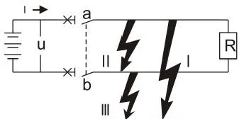
تطبيق نظام التيار المستمر: يجب مراعاة الجوانب التالية قبل اختيار القاطع في نظام التيار المستمر.
أ. جهد التشغيل المقنن، مع مراعاة عدد الأقطاب المتسلسلة
ب. التيار المقنن، مع مراعاة قدرة الحمل
ج. قدرة القطع، مع مراعاة أقصى تيار قصر في موقع التركيب
د. وضع نظام التأريض، انظر sheet 5
| نوع النظام | نظام التأريض | نظام غير مؤرض | ||
| جميع أنواع الأعطال | 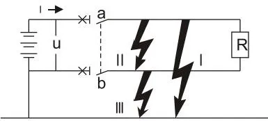 |
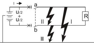 |
 |
|
| تأثير العطل | العطل الأول | توليد أقصى تيار قصر الاتصال المتصل بالقطب الموجب ينقطع |
جهد U/2 ينتج أقصى تيار قصر الاتصال المتصل بالقطب السالب ينقطع |
لا تأثير |
| العطل الثاني | توليد أقصى تيار قصر جميع الاتصالات المتسلسلة تنقطع |
توليد أقصى تيار قصر جميع الاتصالات المتسلسلة تنقطع |
توليد أقصى تيار قصر جميع الاتصالات المتسلسلة تنقطع |
|
| العطل الأول | لا تأثير | نفس العطل الأول ولكن فقط للاتصال المتصل بالقطب السالب |
لا تأثير | |
| أسوأ حالة | العطل الأول | العطل الأول والعطل الثاني | العطل الثاني | |
| حالة القطع | التسلسل في القطب الموجب والقطع معًا | لكل قطب، قطع أقصى تيار قصر عند U/2 | قطبان ينقطعان معًا | |
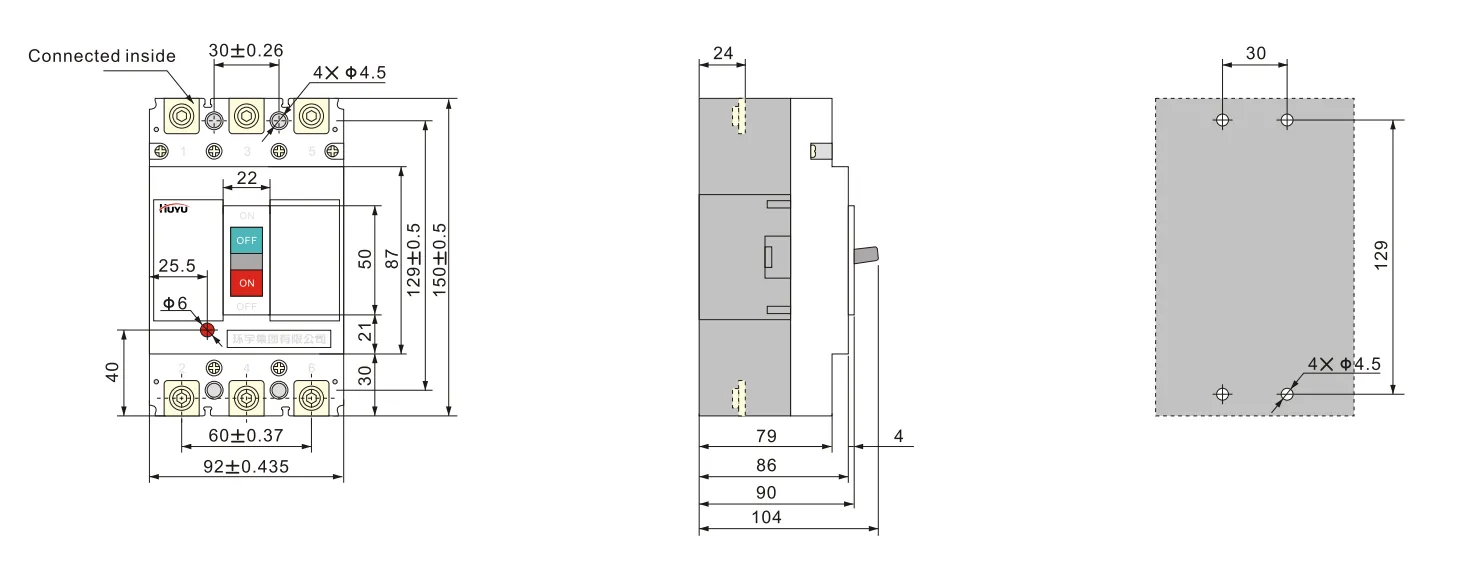
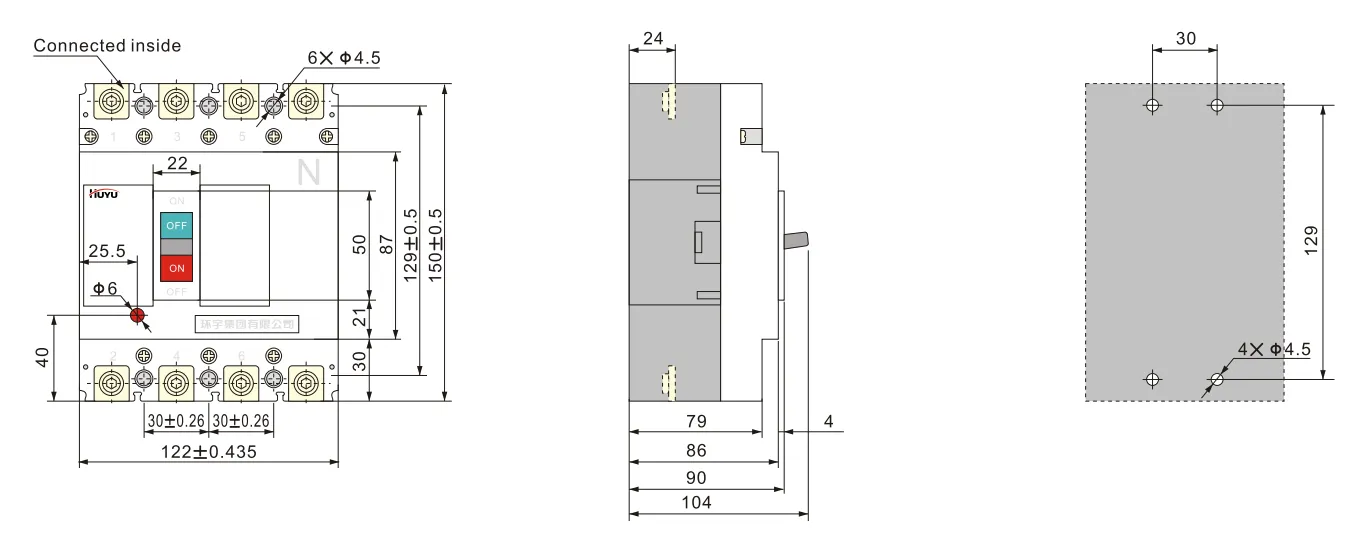
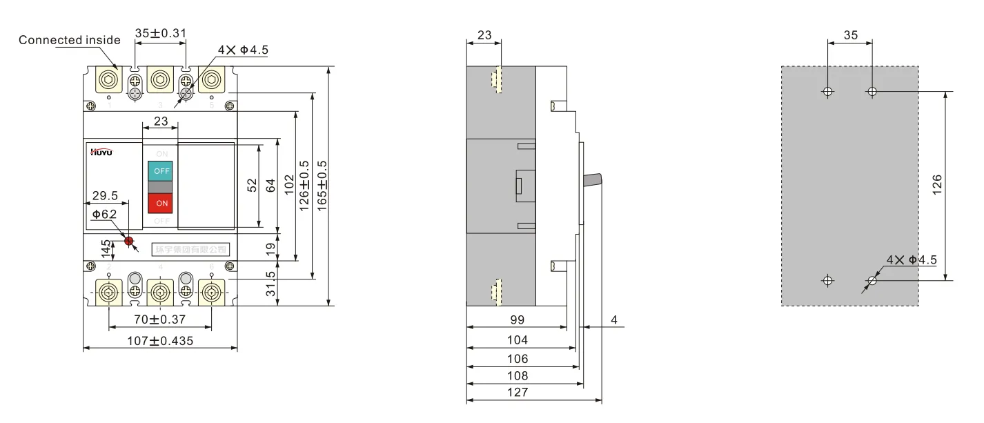
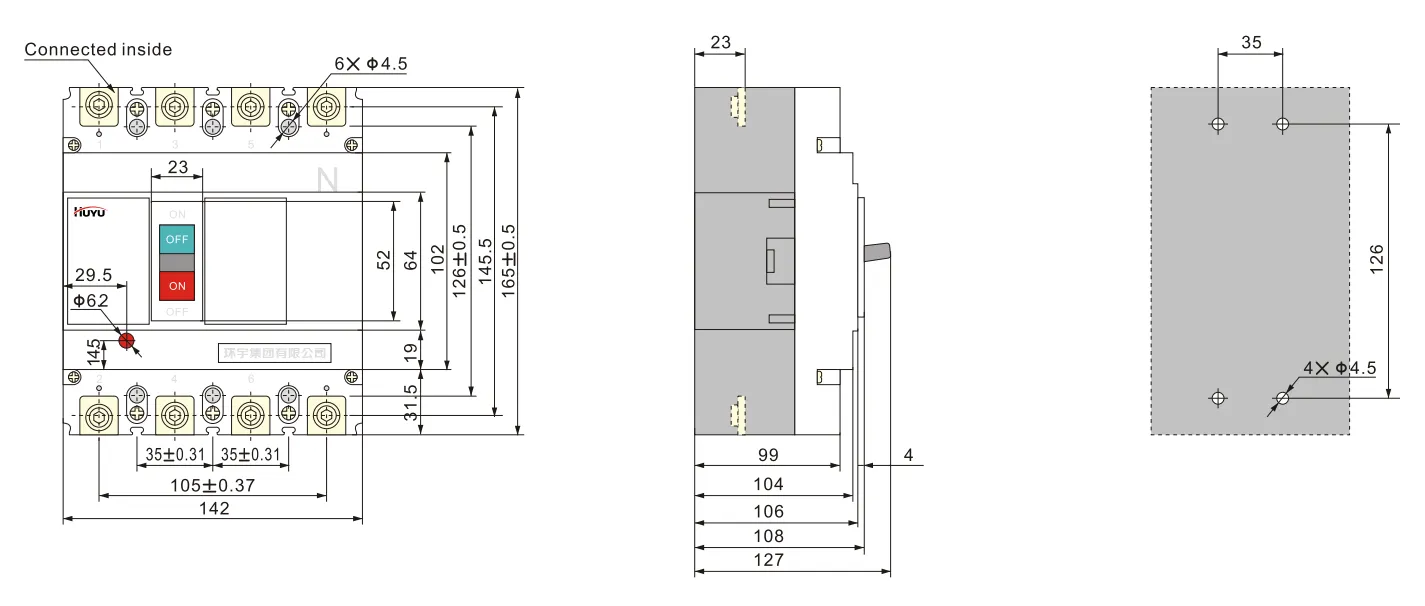
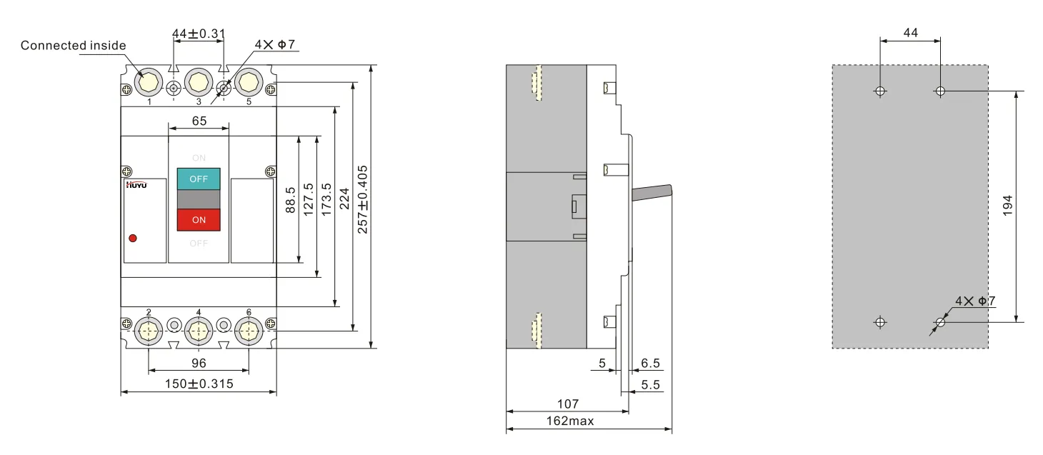
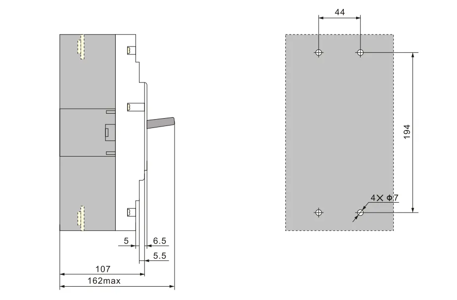
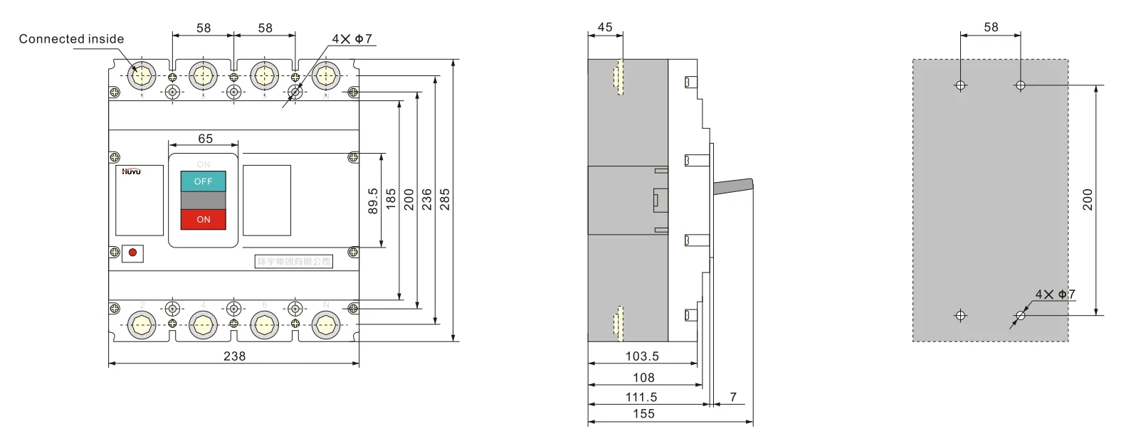
الأبعاد الكلية وأبعاد التركيب
توصيل نوع E لـ 3PHUM8PV-125 (الاتصال الأمامي)
توصيل نوع H لـ 4P HUM8PV-125 (الاتصال الأمامي)
توصيل نوع E لـ 3P HUM8PV-250 (الاتصال الأمامي)
توصيل نوع H لـ 4PHUM8PV-250 (الاتصال الأمامي)
توصيل نوع E لـ 3PHUM8PV-400 (الاتصال الأمامي)
توصيل نوع H لـ 4P HUM8PV-400 (الاتصال الأمامي)
توصيل نوع E لـ 3PHUM8PV-630 (الاتصال الأمامي)
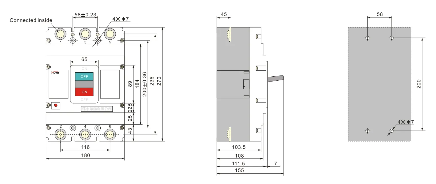
توصيل نوع H لـ 4P HUM8PV-630 (الاتصال الأمامي)
الملحقات
يمكن توفير الملحقات حسب متطلبات المستخدم.
معلمات إطلاق الشنت:
الجهد المقنن Us: AC230V, 400V; DC 220-250V, 24-30V
يمكن للقاطع أن يفصل بثقة عند (70%-110%) Us، ووقت العمل هو 10 مللي ثانية - 30 مللي ثانية.
ملاحظة: عند استخدام إطلاق شنت DC24V-30V، يجب أن يفي الحد الأقصى لطول خط النحاس بمتطلبات الجدول 6
| جهد التحكم المقنن Us (تيار مستمر 24 فولت~30 فولت) |
طاقة الإدخال | الحد الأقصى لطول خط النحاس | |
| 5 مم² | 5 مم² | ||
| 100%Us | 50 واط | 150 م | 250 م |
| 85%Us | 50 واط | 100 م | 160 م |
القيمة المقننة للاتصال المساعد واتصال الإنذار:
التيار الحراري التقليدي Ith=3A؛ التيار العامل المقنن Ie=0.79A (AC230V)؛ Ie=0.47A (AC400V)؛ Ie=0.15A (DC250V)
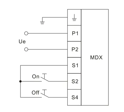
معلمات آلية تشغيل المحرك انظر الجدول 7، الارتفاع الكلي لآلية تشغيل المحرك انظر الجدول 8. فيما يلي مخطط التوصيل لآلية تشغيل المحرك
| التيار المقنن لحجم الإطار Ie (A) | جهد العمل المقنن Ue (V) | تيار البدء (A) | وقت العمل (ثواني) | تردد التشغيل المقنن (مرات/ساعة) | العمر الميكانيكي (مرات) |
| 125 | تيار متردد 110 فولت~230 فولت 50Hz تيار مستمر 110 فولت~220 فولت |
≤0.5 | ≤0.8 | 180 | 9000 |
| 250 | |||||
| 400 | ≤2 | 120 | 5000 | ||
| 630 | 3000 |
يجب أن تكون قدرة الطاقة لآلية تشغيل المحرك كافية لضمان أن الجهد المؤثر عند تيار البدء لا يقل عن 85%Ue
| النموذج | HUM8PV-125 | HUM8PV-250 | HUM8PV-400 | HUM8PV-630 |
| الارتفاع | 170 | 199 | 230 | 246 |
مخطط التوصيل لآلية تشغيل المحرك
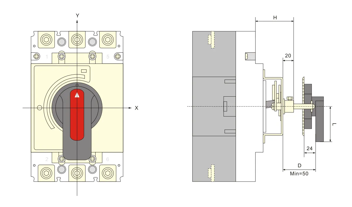
حجم التثبيت لآلية تشغيل المقبض الدوار انظر الجدول 9
| النموذج | HUM8PV-125 | HUM8PV-250 | HUM8PV-400 | HUM8PV-630 |
| حجم التثبيت (H) | 54 | 54 | 76 | 83 |
الرسم العام وفتحة التثبيت لمقبض نوع A (مربع)
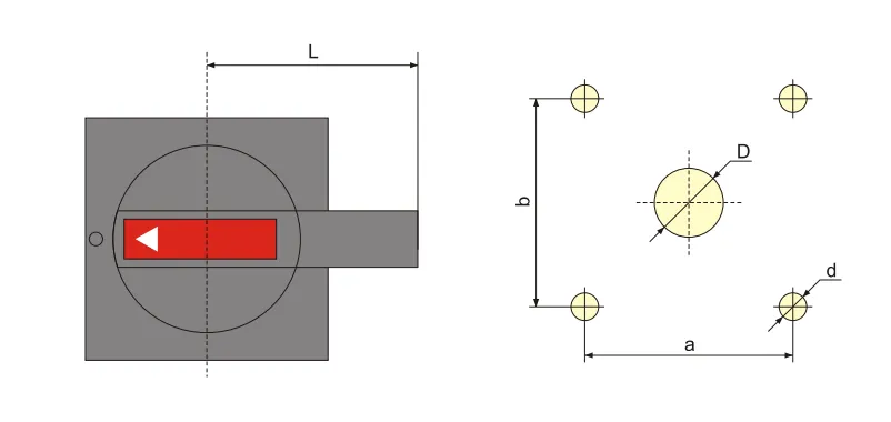
| الطراز والمواصفات | A1 | A2 |
| D | 中42 | φ 63 |
| d | 中4.5 | φ5.5 |
| a | 65 | 88 |
| b | 65 | 88 |
| L | 60 | 140 |
الرسم العام وأبعاد ثقوب التثبيت لمقبض نوع B (دائري)
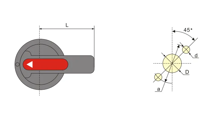
| الطراز والمواصفات | B1 | B2 | B3 |
| D | φ33 | φ33 | 中33 |
| d | 中4.5 | φ4.5 | 中4.5 |
| a | φ 53 | φ53 | φ53 |
| L | 65 | 125 | 95 |
الأبعاد العامة وأبعاد التثبيت لآلية تشغيل المقبض الدوار المركز
التركيب والصيانة
الأمور التي يجب الانتباه إليها قبل التركيب:
أ. يجب أن يكون المظهر جيدًا وأن لا يكون هناك تحميل؛ يجب أن تتوافق القيمة المقدرة للقاطع والملحقات مع ظروف العمل في موقع التثبيت؛ لا يوجد صدمة واضحة في موقع التثبيت ويجب أن تتوافق مع ظروف العمل العادية
ب. يجب إجراء اختبار العزل قبل خروج المصنع. استخدم مقياس مقاومة 1000 فولت تيار مستمر لإعادة الاختبار قبل التركيب، بين أقطاب قاطع الدائرة، يجب ألا تقل مقاومة العزل بين الطرف الداخل والخارج لنفس القطب عن 20 ميجا أوم في حالة الفصل
يجب أن يتجاوز مقطع الموصلات الحجم المنظم في الورقة 10، ويجب شد برغي التوصيل بإحكام.
يجب أن تتوافق خصائص القاطع والملحقات مع متطلبات طلبنا.
يمكن لمقبض القاطع الدوران إلى وضع “تشغيل”، “إيقاف”، “فصل”، وعندما يكون في وضع “فصل”، يمكن تدوير المقبض إلى اتجاه “إيقاف”، ثم يمكن إجراء عملية “تشغيل”.
قبل إضافة الملحقات الداخلية، يجب أن يكون قاطع القاطع مفصولًا.
| التيار المقنن (أ) | 10 | 16، 20 | 25 | 32 | 40، 50 | 63 | 80 | 100 | 125 | 160 | 180، 200، 225 | 250 | 315، 350 | 400 |
| مساحة مقطع الخط | 1.5 | 2.5 | 4 | 6 | 10 | 16 | 25 | 35 | 50 | 70 | 95 | 120 | 185 | 240 |
| التيار المقنن (أ) |
مساحة مقطع الكابل | حجم شريط النحاس | ||
| الكمية | مساحة المقطع العرضي (مم²) | الكمية | الحجم (مم×مم) | |
| 500 | 2 | 150 | 2 | 30×5 |
| 630 | 2 | 185 | 2 | 40×5 |
معلومات الطلب
اسم المنتج والطراز
التيار المقنن، نوع الإطلاق، مضاعف تيار ضبط الإطلاق اللحظي
اسم الملحقات والمواصفات
الأسئلة الشائعة
ما هو قاطع الدائرة ذو الغلاف المصبوب؟
قاطع الدائرة ذو الغلاف المصبوب (MCCB) هو جهاز حماية مغلق في غلاف مصبوب. يوفر حماية من التيار الزائد والدوائر القصيرة للدوائر الكهربائية، مع إعدادات إطلاق قابلة للتعديل وقدرات قطع أعلى من قواطع الدائرة المصغرة.
ما هو قاطع الدائرة الكهروضوئي؟
قاطع الدائرة الكهروضوئي مصمم خصيصًا لتطبيقات التيار المستمر الشمسية. يتعامل مع الخصائص الفريدة لأنظمة الطاقة الشمسية — جهد تيار مستمر أعلى (حتى 1000 فولت أو 1500 فولت تيار مستمر)، إخماد قوس تيار مستمر بدون عبور الصفر، وتغيرات مستمرة في الحمل نتيجة للإشعاع الشمسي.
ما الفرق بين قاطع الدائرة والقاطع ذو الغلاف المصبوب؟
“قاطع الدائرة” هو مصطلح عام لأي جهاز حماية تلقائي من التيار الزائد. “قاطع الدائرة ذو الغلاف المصبوب” (MCCB) هو نوع محدد — مغلف في غلاف عازل مصبوب، مع تصنيفات تيار أعلى (حتى عدة آلاف من الأمبيرات)، إعدادات إطلاق قابلة للتعديل، وقدرات قطع أعلى من قواطع الدائرة المصغرة (MCBs).
أيهما أفضل، ACB أم MCCB؟
لا يوجد “أفضل” بشكل عام — كل منهما يخدم تطبيقات مختلفة. ACB (قاطع الدائرة الهوائي) يستخدم للتوزيع الرئيسي منخفض الجهد (تيار عالي، حتى 6300 أمبير)، مع حماية قابلة للتعديل وقدرة قطع عالية. MCCB (قاطع الدائرة ذو الغلاف المصبوب) يستخدم لحماية دوائر الفروع (حتى 1600 أمبير)، أكثر إحكامًا وفعالية من حيث التكلفة لدوائر التغذية. اختر بناءً على تصنيف التيار ومتطلبات الحماية للتطبيق.