В ваш коммерческий объект приходит специалист для проведения электрической проверки. Инженер сообщает ему, что сопротивление заземляющего электрода было измерено и составило 22 Ом. Кто-то рядом говорит, что поскольку NEC допускает 25 Ом, то всё в порядке. Но руководство производителя оборудования указывает, что максимальное сопротивление должно быть 5 Ом, так как оборудование работает с чувствительной электроникой; поэтому инженер по вводу в эксплуатацию ссылается на спецификацию, которая для вас новая. Какое значение следует учитывать? Этот вопрос очень распространён среди специалистов, работающих в коммерческой электротехнике, но ответ зависит от стандарта, по которому проводится измерение.
В этом тексте вы сразу получите ответ с точными цифрами — без использования вымышленных значений. Вы узнаете, что именно требует NEC, что говорит IEEE, как работает “правило 25 Ом” и что считается безопасным.
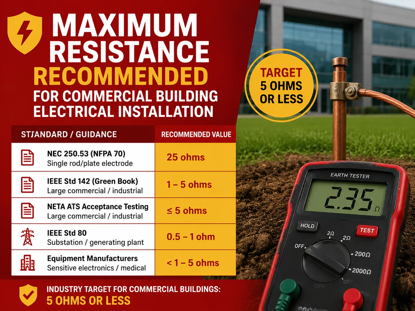
Если вы ищете быстрый ответ, то универсального чёткого значения максимального сопротивления заземления для всех коммерческих зданий не существует, поскольку ответ зависит от того, какой стандарт и какую часть системы вы имеете в виду. NEC (NFPA 70) не устанавливает общего максимального сопротивления здания, но сочетание 25 Ом (которое фактически указано в 250.53) имеет практический смысл при обсуждении только заземляющего стержня или пластины и используется для определения, достаточно ли одного стержня или пластины в качестве заземляющего электрода (то есть, если сопротивление одного электрода 25 Ом или ниже, второй электрод не требуется). Для крупных коммерческих и промышленных систем стандарт IEEE Std 142 (“Зелёная книга”) указывает, что сопротивление основного заземляющего электрода к земле должно находиться в диапазоне от 1 до 5 Ом, а практика отрасли (рекомендации NFPA/IEEE, процедуры NETA ATS, стандарты телекоммуникационной отрасли и др.) стремится к значению около 5 Ом для коммерческих зданий и даже 1 Ом для подстанций и электростанций. В итоге минимальные требования NEC не связаны с требованиями к характеристикам, установленными IEEE в диапазоне 1-5 Ом для коммерческих зданий, что является общепринятой целевой величиной в отрасли, в то время как значения выше 25 Ом считаются плохими и неприемлемыми для заземляющего электрода в коммерческих объектах.
Будем точны, потому что именно здесь возникает дезинформация. Соответствующие значения с их источниками:
| Стандарт / Руководство | Значение | К чему применяется |
|---|---|---|
| NEC 250.53 (NFPA 70) | 25 Ом | Один стержень/пластина — если сопротивление не превышает 25 Ом, второй электрод не требуется |
| Значение по умолчанию NEC 250.53 | Два электрода | Стержневые/трубчатые/пластинчатые электроды по умолчанию устанавливаются в количестве двух; тест на 25 Ом не требуется, если оба установлены |
| IEEE Std 142 (Зелёная книга) | 1–5 Ом | Рекомендуемое сопротивление заземления основного электрода для крупных коммерческих и промышленных систем |
| IEEE Std 80 | 0,5–1 Ом | Заземляющие сети подстанций / электростанций |
| Руководства отрасли NFPA/IEEE | 5 Ом или меньше | Часто цитируемая целевая величина для коммерческих объектов; стандарт телекоммуникационной отрасли |
| Приёмочные испытания NETA ATS | 5 Ом / 1 Ом | ≤5Ω для крупных коммерческих/промышленных объектов; ≤1Ω для генерирующих/трансформаторных станций |
| Производители оборудования | <1 до 5 ом | Технические характеристики чувствительной электроники / медицинского диагностического оборудования |
Важный факт: в NEC нет требования, чтобы коммерческое заземление было “25 ом или меньше”. Число 25 включено только для определения достаточного расстояния от одного электрода. Требования по производительности, такие как IEEE 142 и рекомендации NETA, а также практика, предполагают значение от 1 до 5 ом — при этом 5 ом является наиболее часто используемым пределом.
Правило NEC о 25 омах — что оно действительно означает
Согласно разделу NEC 250.53(A)(2) (а также разделу 250-56 NEC 2005 года), кодекс требует установку двух заземляющих электродов. Однако существует важное исключение, которое допускает один электрод, если он соответствует требуемому сопротивлению заземления 25 ом или меньше. К сожалению, это часто неправильно интерпретируется как возможность установить только один электрод, проверить его сопротивление, а затем добавить второй электрод, если первый не соответствует требованию сопротивления в 25 ом.
На самом деле, распределение следующее:
- По умолчанию = два электрода, установленные на расстоянии не менее 6 футов друг от друга.
- Допускается = один электрод, прошедший надлежащий тест сопротивления, подтверждающий, что сопротивление заземления составляет 25Ω или меньше.
В случае установки второго электрода комбинация не обязана соответствовать условию 25 ом — поскольку второй электрод считается соответствующим требованиям NEC по факту установки.
IEEE 142 (Зеленая книга): рекомендация 1–5 Ом
Вопрос “какое рекомендуемое сопротивление для коммерческого здания?” получает авторитетное инженерное решение в IEEE Std 142, известном как Зеленая книга. Рекомендация — сопротивление заземления от 1 до 5 ом для основного заземляющего электрода в крупных промышленных и коммерческих системах.
Причина предпочтения этого значения сопротивления вместо 25 ом заключается в том, что коммерческие объекты часто оснащены чувствительной электроникой и т. д., и поэтому нуждаются в очень стабильной и низкоимпедансной заземляющей системе, чего недостаточно при минимальных требованиях кода. Низкое сопротивление заземления, указанное выше, обеспечивает:
- Более быстрый возврат тока короткого замыкания к источнику
- Меньшее повышение напряжения на корпусе оборудования во время неисправности
- Лучшее рассеивание импульсов молнии
- Меньше электрических помех
В итоге, кодекс требует 25 ом; с инженерной точки зрения, для хорошей работы требуется значение 1-5 ом.
Отраслевая практика: 5 Ом как коммерческая цель
На практике большинство людей слышат для коммерческих систем “5 ом или меньше”. Это исходит из различных, но взаимодополняющих источников, таких как:
- рекомендации NFPA и IEEE о 5,0 ом или меньше как хорошей цели
- подходы в телекоммуникациях (5 ом или меньше для заземления и соединения)
- стандарты NETA для приемочных испытаний (≤5 ом для коммерческих/промышленных систем; ≤1 ом для электростанций/трансформаторных подстанций)
- цифры, приведённые различными производителями оборудования (от 1 до 5 ом для чувствительной электроники)
Согласно общим рекомендациям различных инженеров и тестировщиков, 5 ом или меньше считается хорошим показателем для коммерческих зданий, в то время как среднее значение для подстанций составляет 1 ом и меньше. Это не требование NEC, но это лучшие практики, которым следуют многие проектировщики и которые подлежат тестированию.
Существует ли безопасный диапазон? Понимание чисел
Вот как на практике интерпретировать показания сопротивления заземления:
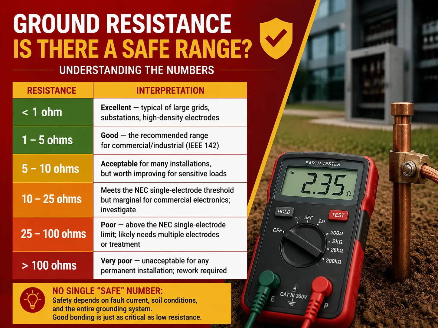
| Сопротивление | Интерпретация |
|---|---|
| < 1 Ом | Отлично — типично для крупных сетей, подстанций, электродов высокой плотности |
| 1–5 Ом | Хорошо — рекомендуемый диапазон для коммерческих/промышленных объектов (IEEE 142) |
| 5–10 Ом | Приемлемо для многих установок, но стоит улучшить для чувствительных нагрузок |
| 10–25 Ом | Соответствует порогу NEC для одиночного электрода, но гранично для коммерческой электроники; требуется проверка |
| 25–100 Ом | Плохо — выше предела NEC для одиночного электрода; вероятно, необходимы несколько электродов или обработка |
| > 100 Ом | Очень плохо — неприемлемо для любой постоянной установки; требуется доработка |
Основное предупреждение следующее: не существует универсального “безопасного” значения, применимого к каждой ситуации с точки зрения безопасности — оно также зависит от различных факторов, таких как ток замыкания на землю, условия почвы и фактическая схема. Качество сопротивления заземляющего электрода — лишь часть проблемы; целостность всей системы заземления не менее важна. Идеальный электрод с сопротивлением 2 Ом бесполезен, если заземляющие проводники устройств искривлены или корродированы.
Является ли 20 Ом плохим? Интерпретация вашего измерения
Уровни сопротивления 20 Ом не считаются положительными в строительных нормах для коммерческих зданий, но при этом с этим значением не связано нарушений норм, следовательно:
- Стандарт NEC: Этот уровень ниже максимального значения для одиночного электрода, установленного вышеуказанным законодательством. Тем не менее, уровень сопротивления 20 Ом близок к превышению стандартов, в зависимости от сезонного повышения и снижения влажности почвы.
- Стандарт IEEE 142: Согласно этому стандарту, уровень сопротивления 20 Ом превышает рекомендуемое значение 1-5 Ом, что означает, что часть электронного оборудования, например, предотвращающего операции с перенапряжением, может быть повреждена из-за неправильного уровня заземления.
На практике любая коммерческая организация обеспечит соответствие заземления установленным стандартам.
Вывод: В общем, сопротивление 20 Ом может не угрожать безопасности здания, но оно все же слишком высоко для коммерческого здания; поэтому требуется улучшение.
Другие коммерческие требования: розетки и соединение
Сопротивление заземления является частью коммерческой электрической безопасности. Требования Национального электрического кодекса (NEC) следующие:
- Характеристики коммерческих розеток (NEC 406, 210.52, 210.8): Коммерческие розетки должны быть специфицированы как типы 125В, 15А и/или 20А, защита GFCI необходима в определенных местах (ванные комнаты, крыши, кухни, наружные места и т.д. согласно 210.8(B)), все розетки должны быть подключены к металлической коробке, и каждое гнездо должно быть обеспечено подключением к заземляющему проводнику.
- Процесс соединения (NEC 250.102-250.104): Важно понимать, что все металлические части, которые могут оказаться под напряжением, такие как трубы, каркасное оборудование, конструкционная сталь, насосное оборудование, должны быть соединены с системой заземления. Следует отметить, что проверка непрерывности соединения будет проводиться отдельно от измерения сопротивления электрода (сопротивление между точками не должно превышать 0,5 Ом при подключенном оборудовании к системе заземления).
- Проводник заземляющего электрода (NEC 250.66): Заземляющие электроды должны иметь размер, соответствующий обслуживанию, не превышать максимальный диаметр и обеспечивать соединение системы заземления с обслуживающим оборудованием.
Если вы также проверяете защитные устройства в цепи, наше объяснение автоматических выключателей и устройств защитного отключения по току утечки проясняет, какая защита за что отвечает в коммерческом щите.
Что считается высоким электрическим сопротивлением?
Контекст играет роль в том, что означает “высокое сопротивление”:
- При измерении заземляющих электродов это означает значение выше примерно 25 Ом (например, 100 Ом и выше — очень высокое значение). “Идеальный” уровень сопротивления — 1-5 Ом.
- В терминах непрерывности заземления любое значение выше 0,5 Ом указывает на неисправность. Соединение между оборудованием и землей должно быть практически нулевым.
- Что касается сопротивления изоляции, высокое значение сопротивления означает хорошее сопротивление, так как оно измеряется в мега- и гигаомах, где любое значение ниже 1 МОм указывает на высокую вероятность пробоя.
В заключение, “высокое сопротивление” почти всегда означает проблему (для заземления), но может означать хорошее состояние (для изоляции). Всегда уточняйте, о чем именно идет речь при использовании термина “высокое сопротивление”.
Факторы, влияющие на сопротивление заземления
Сопротивление заземления не является постоянным значением. Оно варьируется в зависимости от условий:
- Удельное сопротивление почвы: глина/суглинок (10–100 Ω·м) имеют более низкое сопротивление, чем песок/гравий (1 000–10 000 Ω·м).
- Влажность: влажные почвы имеют более низкое сопротивление, тогда как сухая погода значительно увеличивает сопротивление.
- Температура: холодная почва имеет значительно более высокое сопротивление.
- Глубина и сечение электрода: более длинные электроды и большие пластины проникают глубже в почву.
- Количество и расстояние между электродами: чем больше электродов и чем дальше они расположены друг от друга, тем ниже сопротивление.
- Материал электрода и коррозия: чем дольше электроды находятся в земле, тем сильнее коррозия и тем выше сопротивление.
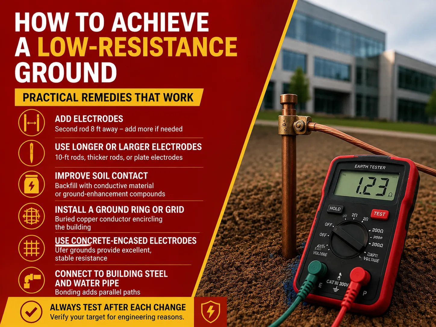
Как достичь низкого сопротивления заземления
Если сопротивление вашего коммерческого заземления слишком высоко, вот ранжированный список наиболее экономичных решений:
- Добавьте электроды: добавление второго заземляющего электрода, установленного на расстоянии 8 футов от первого, значительно снизит сопротивление. Продолжайте добавлять дополнительные электроды, пока не будет достигнуто необходимое сопротивление (выгода от каждого следующего электрода уменьшается).
- Используйте более длинные или толстые электроды: использование более длинного электрода (10 футов) или толстых электродов или пластин поможет достичь более глубоких и менее сопротивляющихся слоев почвы.
- Улучшите контакт с почвой: Засыпка вокруг электрода проводящими материалами или химическими добавками улучшит его контакт с почвой.
- Создайте заземляющие кольца или сетку: Подземный медный проводник, окружающий конструкцию, создает большую площадь контакта (это решение широко используется в коммерческой и промышленной сфере).
- Используйте электроды, залитые бетоном (заземления Ufer): Арматура и проводник, встроенные в бетон, демонстрируют отличные и надежные проводящие свойства.
- Подключение к стальным частям здания и водопроводу: Подключение к металлическим конструкционным стальным элементам и подземным водопроводным трубам (если таковые имеются) обеспечивает дополнительные пути проводимости.
Обязательно проводите тестирование каждый раз при изменении системы, но имейте в виду, что NEC не требует повторного тестирования двухэлектродной системы.
Как проводится тестирование сопротивления заземления
Тестирование заземления должно выполняться квалифицированными специалистами. Основные и широко распространённые методы:
- Метод падения потенциала (более известный как трёхточечное тестирование): Метод падения потенциала заключается в использовании двух временных колышков и измерении сопротивления с увеличением расстояния. Это самый точный метод, применяемый для малых и средних установок.
- Зажимное (или индуктивное) тестирование: Метод зажима включает зажим вокруг стержня/проводника, что позволяет измерять сопротивление контура без разъединения контура. Он удобен для уже существующих установок, но требует подключения всего контура.
- Двухточечное тестирование: Метод двух точек используется для быстрого измерения относительно известного эталонного электрода; эта техника менее точна и применяется для приблизительных расчетов.
Тестирование опасно, так как обычно требует изоляции электрода, и может присутствовать ток повреждения, поэтому эту работу не должен выполнять обычный домовладелец. Для коммерческих зданий пусконаладочные и регулярные испытания обычно выполняются подрядчиками или специализированными компаниями в соответствии со стандартами NETA.
Часто задаваемые вопросы
Какое руководство определяет допустимое максимальное сопротивление заземления в коммерческих установках?
NEC не устанавливает единого стандартного максимального значения. Требование в 25 Ом, указанное в NEC 250.53, применяется только к системе с одним электродом, а не ко всему зданию. Основным инженерным стандартом является IEEE Std 142 (Зеленая книга), который рекомендует, чтобы значение основного заземляющего электрода в крупных коммерческих и промышленных установках находилось в диапазоне от 1 до 5 Ом. Обычно на практике и с учетом стандартов NETA значение 5 Ом считается удовлетворительным для коммерческого здания (1 Ом для подстанции). В общем, NEC устанавливает пределы согласно требованиям кода, IEEE 142 предоставляет допустимый диапазон согласно инженерным требованиям, и в итоге 5 Ом становится принятой практикой.
Является ли сопротивление заземления в 20 Ом плохим?
Сопротивление в 20 ом не является опасным само по себе, но является погранично приемлемым для коммерческих зданий. Хотя критерий NEC для одиночного электрода в 25 ом соблюдается, это значение превышает уровень, рекомендованный IEEE 142 для коммерческих установок, который составляет 1–5 ом, а также общепринятый уровень в 5 ом. При таком уровне заземления ток повреждения возвращается медленнее и не обеспечивает значительной защиты от перенапряжений или опорного заземления для чувствительной электроники. И поскольку это всего лишь шаг до превышения порога, установленного кодексом, уровень может увеличиться из-за изменений условий почвы в течение сезонов. Следовательно, систему заземления следует улучшить в случае коммерческих установок.
Каковы требования NEC к коммерческим розеткам?
Все коммерческие розетки имеют номинальное напряжение 125 вольт и ток 15 или 20 ампер, как указано в NEC 406, а их минимальное количество и правила расположения можно найти в 210.52 для общих зон. Защита GFCI обязательна в определённых коммерческих помещениях согласно NEC 210.8(b), таких как ванные комнаты, кухни, крыши, улицы и гаражи/сервисные зоны. Все розетки должны быть обеспечены заземлением оборудования, а металлические коробки должны быть заземлены. Во многих коммерческих помещениях, предназначенных для детей, обязательны розетки с защитой от вмешательства, в то время как для некоторых типов помещений существуют свои особые правила по обеспечению розеток.
Что такое высокое электрическое сопротивление?
“Высокое электрическое сопротивление” зависит от того, какое измерение имеется в виду. В отношении заземляющих электродов всё, что превышает примерно 25 ом, считается высоким, а значения свыше 100 ом — очень высоким. Идеально, если сопротивление находится в диапазоне от 1 до 5 ом. Что касается непрерывности заземления оборудования, электрическое сопротивление не должно превышать 0,5 ома при измерении оборудования и заземления. В изоляции высокое сопротивление является положительным признаком. Для того чтобы изоляция считалась исправной, её сопротивление должно составлять миллионы ом (МОм) или даже миллиарды ом. Уровень сопротивления менее 1 МОм указывает на повреждение с риском утечки.
Ссылки
- NFPA 70 — Национальный электрический кодекс (NEC), статья 250 (Заземление и соединение), 210.8, 406
- IEEE Std 142-2007 — Рекомендуемая практика заземления промышленных и коммерческих энергетических систем (Зелёная книга)
- IEEE Std 81 — Руководство по измерению сопротивления земли, импеданса заземления и потенциалов поверхности земли
- NETA — Спецификации приемочных испытаний (ATS) для электроэнергетического оборудования
- Vertiv — Почему необходимо тестировать системы заземления (значения заземления NEC/IEEE 142/80)
- Fluke — Примечания к применению для тестирования сопротивления заземления
Заключение
Два показателя NEC — 25 Ом и 1-5 Ом согласно руководству IEEE 142 охватывают максимально допустимое электрическое сопротивление заземления коммерческого здания. В то время как NEC не рассматривает для коммерческого здания значение ниже 25 Ом как соответствие коду в качестве стандарта производительности, это зависит от того, достаточно ли одного электрода. С этой точки зрения, идеальное значение для надежной и безопасной работы коммерческой установки будет в диапазоне 1-5 Ом, как отмечено IEEE, что способствует быстрому устранению отказов, эффективной защите от перенапряжений, низкому уровню шума для коммерческой электроники.
Используйте правильное тестирование падения потенциала для получения точного измерения и сопоставьте его с таблицей диапазонов (хорошее значение — ниже 5, значение от 5 до 25 — пограничное, значение выше 25 — ниже приемлемого уровня); возможно, потребуется добавить больше или более длинных электродов в систему заземления, если показания не удовлетворительны. Наконец, не забывайте, что сопротивление электродов — это только половина истории, и необходимо также учитывать непрерывность соединения и заземления.