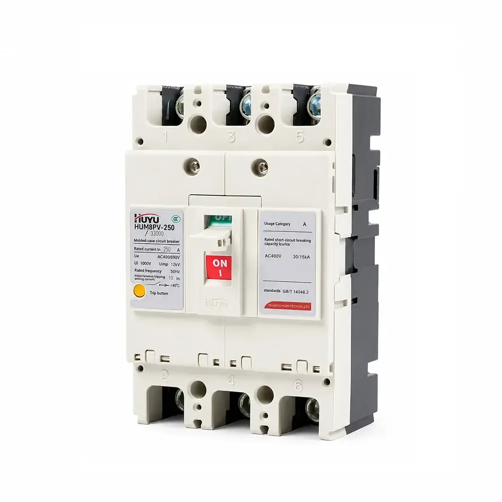
HUM8PV เบรกเกอร์วงจรแบบหล่อสำหรับพลังงานแสงอาทิตย์
ซีรีส์ HUM8PV เป็นเบรกเกอร์วงจรแบบหล่อโฟโตโวลตาอิกที่มีการจัดอันดับ 16A–690A ที่ DC 1000V มีการป้องกันการลัดวงจรแบบทันทีและการล่าช้าระยะยาวจากการโอเวอร์โหลด มีให้เลือกในแบบ 3P และ 4P พร้อมอุปกรณ์เสริมหลายรายการ (การปล่อยชันท์, สัมผัสเสริม/สัญญาณเตือน, กลไกมอเตอร์) สอดคล้องกับ IEC 60947-2 สำหรับระบบโซลาร์เซลล์, กล่องรวมสัญญาณ, และการกระจาย DC.
มาตรฐาน: IEC 60947-2
กระแสไฟฟ้าที่จัดอันดับ: 16A – 690A (กรอบ 125/250/400/630)
แรงดันไฟฟ้าที่จัดอันดับ: DC 1000V
ขั้ว: 3P, 4P
ความสามารถในการตัด (Icu/Ics): สูงสุด 65kA / 50kA (DC750V)
การใช้งาน: ระบบโซลาร์เซลล์, กล่องรวมสัญญาณ, การกระจาย DC, การป้องกันอินเวอร์เตอร์
ข้อมูลผลิตภัณฑ์
การใช้งาน
เบรกเกอร์วงจร HUM8PV (ซึ่งจะเรียกว่าเบรกเกอร์วงจรในที่นี้) ใช้กับวงจร DC ที่มีแรงดันไฟฟ้าที่จัดอันดับสูงสุดถึง DC1000 V และกระแสไฟฟ้าที่จัดอันดับ 16A ถึง 690A มีฟังก์ชันการป้องกันการโอเวอร์โหลดแบบล่าช้าระยะยาวและการป้องกันการลัดวงจรแบบทันที ผลิตภัณฑ์นี้สามารถกระจายพลังงานไฟฟ้าและป้องกันสายไฟและอุปกรณ์จากความเสียหายเนื่องจากการโอเวอร์โหลด, การลัดวงจร, และความล้มเหลวอื่นๆ ผลิตภัณฑ์นี้สอดคล้องกับมาตรฐาน IEC60947-2.
เงื่อนไขการทำงานปกติ
อุณหภูมิแวดล้อม: -25°C~+70°C; อุณหภูมิเฉลี่ยภายใน 24 ชั่วโมง: ≤+35°C
ความสูง: $ ≤ 2000m
ความชื้น: ความชื้นสัมพัทธ์ของอากาศภายใต้ความร้อนสูงสุด +40C ไม่สามารถเกิน 50%; ภายใต้ความเย็นต่ำสุดมีความชื้นสัมพัทธ์สูงกว่า อุณหภูมิต่ำสุดเฉลี่ยในเดือนที่มีความชื้นที่สุดไม่สามารถเกิน +25C และความชื้นสัมพัทธ์เฉลี่ยไม่สามารถเกิน 90%;
ระดับมลพิษ: ชั้น 3
ติดตั้งในสถานที่ที่ไม่มีความเสี่ยงจากการระเบิด, ไม่มีแก๊สที่อาจกัดกร่อนโลหะหรือแก๊สที่อาจทำให้ฉนวนเสียหาย และมีฝุ่นที่นำไฟฟ้าน้อย
ประเภทการติดตั้ง: III
รุ่นและความหมาย
รุ่นและความหมาย
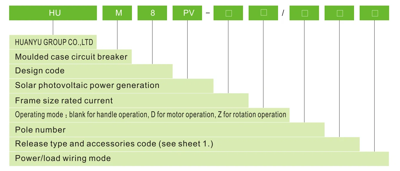
ประเภทการปล่อยและรหัสอุปกรณ์เสริม
| อุปกรณ์เสริม ชื่อ |
ไม่มี อุปกรณ์เสริม |
สัญญาณเตือน สัมผัส |
การปล่อยชันท์ การปล่อย |
เสริม สัมผัส |
การปล่อยชันท์ และเสริม สัมผัส |
สองกลุ่ม ของสัมผัส เสริม |
การปล่อยชันท์ และ สัมผัส |
เสริม สัญญาณเตือน สัมผัส |
การปล่อยชันท์, สัมผัสเสริม และสัญญาณเตือน |
สองกลุ่ม ของสัมผัส เสริม, สัมผัส |
| ประเภทการปล่อยกระแสเกิน | รหัส | |||||||||
| การปลดปล่อยทันที | 200 | 208 | 210 | 220 | 240 | 260 | 218 | 228 | 248 | 268 |
| การปลดปล่อยแบบดูเพล็กซ์ | 300 | 308 | 310 | 320 | 340 | 360 | 318 | 328 | 348 | 368 |
| หมายเหตุ: ตามโหมดการเดินสายไฟฟ้า/โหลด ประเภท E,F สำหรับ 3P; ประเภท G,H,I สำหรับ 4P | ||||||||||
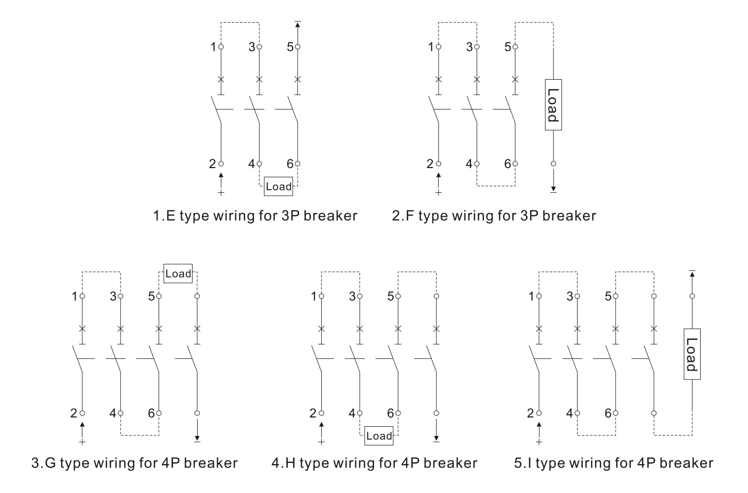
ระบบไฟฟ้าสำหรับโหมดการเดินสายข้างต้น กรุณาตรวจสอบแผ่นที่ 2.
| ระบบฉนวนต่อกราวด์ | ระบบกราวด์ลบ | ระบบกราวด์จุดนิวตรัล | |
| DC500V | E | E、F | – |
| DC750V | E、H | F、G、I | H |
| DC1000V | H | 1 | H |
พารามิเตอร์ทางเทคนิคหลัก
| ขนาดเฟรม กระแสไฟฟ้าที่กำหนด | 125 | 250 | 400 | 630 | |||||
| กระแสไฟฟ้าที่กำหนด In(A) | €�20、25、32、40、50、63、80、100、125 | €�125、160、180、200、225、250 | €�250、315、350、400 | €�500、630 | |||||
| จำนวนขั้ว | 3 | 4 | 3 | 4 | 3 | 4 | 3 | 4 | |
| แรงดันไฟฟ้าสูงสุดที่กำหนด Ui(V) | 1000 | ||||||||
| แรงดันไฟฟ้ากระแทกที่ทนได้ที่กำหนด Uimp(V) | 8000 | ||||||||
| แรงดันไฟฟ้าทำงานที่กำหนด Ue(V) | DC 500 DC750 |
DC750 DC 1000 |
DC 500 DC750 |
DC750 DC 1000 |
DC 500 DC750 |
DC750 DC 1000 |
DC 500 DC750 |
DC750 DC 1000 |
|
| หมวดการใช้งาน | A | ||||||||
| ขีดจำกัด/บริการที่กำหนด วงจรลัด ความสามารถในการตัดวงจร Icu/lcs(kA) |
DC500 | 15/15 | 65/65 | 65/65 | 65/65 | ||||
| DC750 | 5/5 | 15/15 | 40/20 | 50/50 | 40/20 | 50/50 | 40/20 | 50/50 | |
| DC1000 | 5/5 | 40/20 | 40/20 | 40/20 | |||||
| ระยะห่างการลัดวงจร(mm) | ≤50 | ≤50 | ≤100 | ≤100 | |||||
| การทำงาน ประสิทธิภาพ (ครั้ง) |
มีไฟฟ้า | 5000 | 5000 | 1000 | 1000 | ||||
| ไม่มีไฟฟ้า | 10000 | 10000 | 5000 | 5000 | |||||
กราฟลักษณะการป้องกัน
กราฟลักษณะการป้องกันกระแสและอุณหภูมิ HUM8PV-125
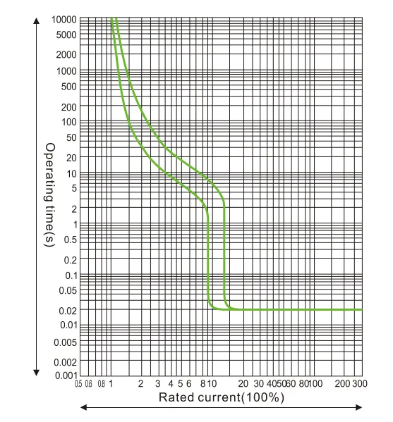
กราฟลักษณะการป้องกันกระแสและอุณหภูมิ HUM8PV-250
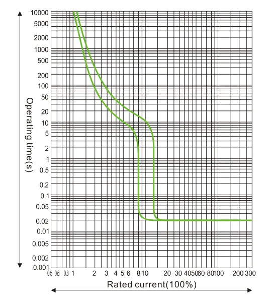
กราฟลักษณะการป้องกันกระแสและอุณหภูมิ HUM8PV-400
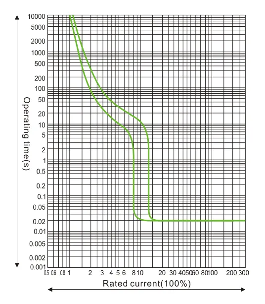
กราฟลักษณะการป้องกันกระแสและอุณหภูมิ HUM8PV-690
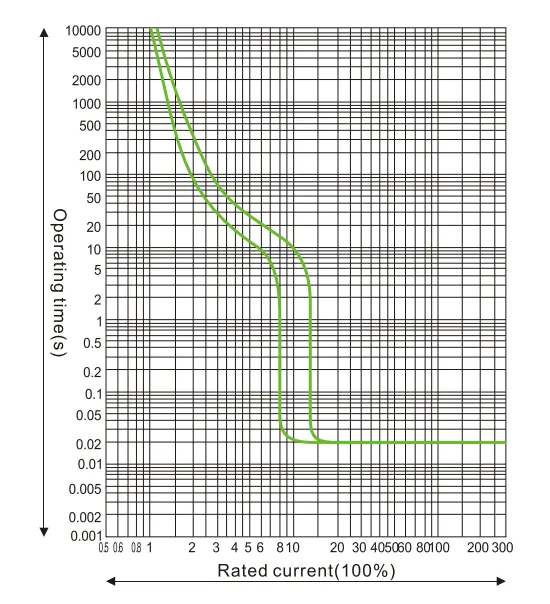
ค่าสัมประสิทธิ์การลดอุณหภูมิที่อุณหภูมิต่างๆ.
| 10℃ | 20℃ | 30℃ | 40℃ | 50℃ | 60℃ | 70℃ | |
| HUM8PV-125 | 15In | 11In | 15In | 1นิ้ว | 93In | 85In | 8In |
| HUM8PV-250 | 15In | 11In | 15In | 1นิ้ว | 93In | 85In | 79In |
| HUM8PV-400 | 16ln | 11In | 15In | 1นิ้ว | 94In | 86ln | 81In |
| HUM8PV-630 | 17In | 11In | 15In | 1นิ้ว | 9In | 8In | 7In |
ค่าสัมประสิทธิ์ลดทอนความสามารถที่ความสูงสูง: เมื่อความสูงเกิน 2000 เมตร เบรกเกอร์ควรปรับตาม sheet4
| ความสูง (ม.) | 2000 | 3000 | 4000 | 5000 |
| แรงดันทนไฟฟ้าความถี่กำลังไฟฟ้า | 3000 | 2500 | 2000 | 1800 |
| ค่าสัมประสิทธิ์ปรับกระแสทำงาน | 1 | 0.94 | 0.88 | 0.83 |
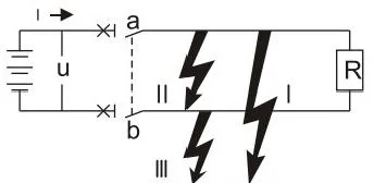
การใช้งานระบบ DC: ควรพิจารณาด้านต่อไปนี้ก่อนเลือกเบรกเกอร์ในระบบ DC.
a. แรงดันใช้งานที่กำหนด โดยพิจารณาจำนวนขั้วแบบเรียงต่อกัน
b. กระแสใช้งานที่กำหนด โดยพิจารณากำลังโหลด
c. ความสามารถในการตัดวงจร โดยพิจารณากระแสลัดวงจรสูงสุดที่ตำแหน่งติดตั้ง
d. รูปแบบระบบกราวด์ ดู sheet 5
| ประเภทระบบ | ระบบกราวด์ | ระบบไม่กราวด์ | ||
| ทุกประเภทของข้อผิดพลาด | 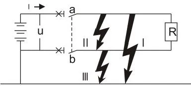 |
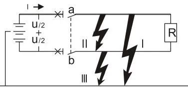 |
 |
|
| ผลกระทบจากข้อผิดพลาด | ข้อผิดพลาด l | สร้างกระแสลัดวงจรสูงสุด การติดต่อเชื่อมต่อกับขั้วบวกตัดวงจร |
แรงดัน U/2 สร้างกระแสลัดวงจรสูงสุด การติดต่อเชื่อมต่อกับขั้วลบตัดวงจร |
ไม่มีผลกระทบ |
| ข้อผิดพลาด ll | สร้างกระแสลัดวงจรสูงสุด การตัดวงจรของทุกการติดต่อเรียงต่อกัน |
สร้างกระแสลัดวงจรสูงสุด การตัดวงจรของทุกการติดต่อเรียงต่อกัน |
สร้างกระแสลัดวงจรสูงสุด การตัดวงจรของทุกการติดต่อเรียงต่อกัน |
|
| ข้อผิดพลาด I | ไม่มีผลกระทบ | เหมือนกับข้อผิดพลาด l แต่เฉพาะสำหรับการติดต่อเชื่อมต่อกับขั้วลบเท่านั้น |
ไม่มีผลกระทบ | |
| สถานการณ์ที่เลวร้ายที่สุด | ข้อผิดพลาด l | ข้อผิดพลาด l และ ข้อผิดพลาด ll | ข้อผิดพลาด ll | |
| สถานการณ์การตัดวงจร | การเชื่อมต่อแบบ Cascade ในขั้วบวกและตัดพร้อมกัน | สำหรับแต่ละขั้ว ตัดกระแสลัดวงจรสูงสุดเมื่อ U/2 | สองขั้วตัดพร้อมกัน | |
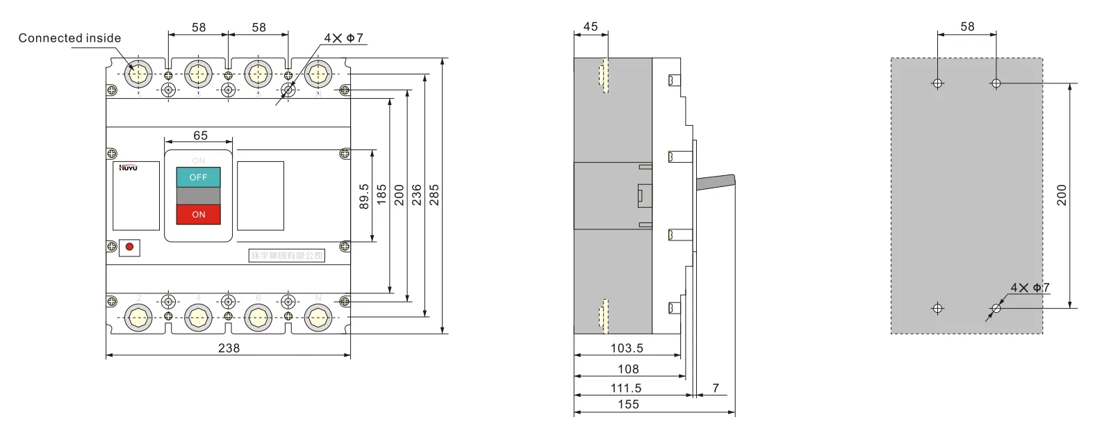
ขนาดโดยรวมและขนาดการติดตั้ง
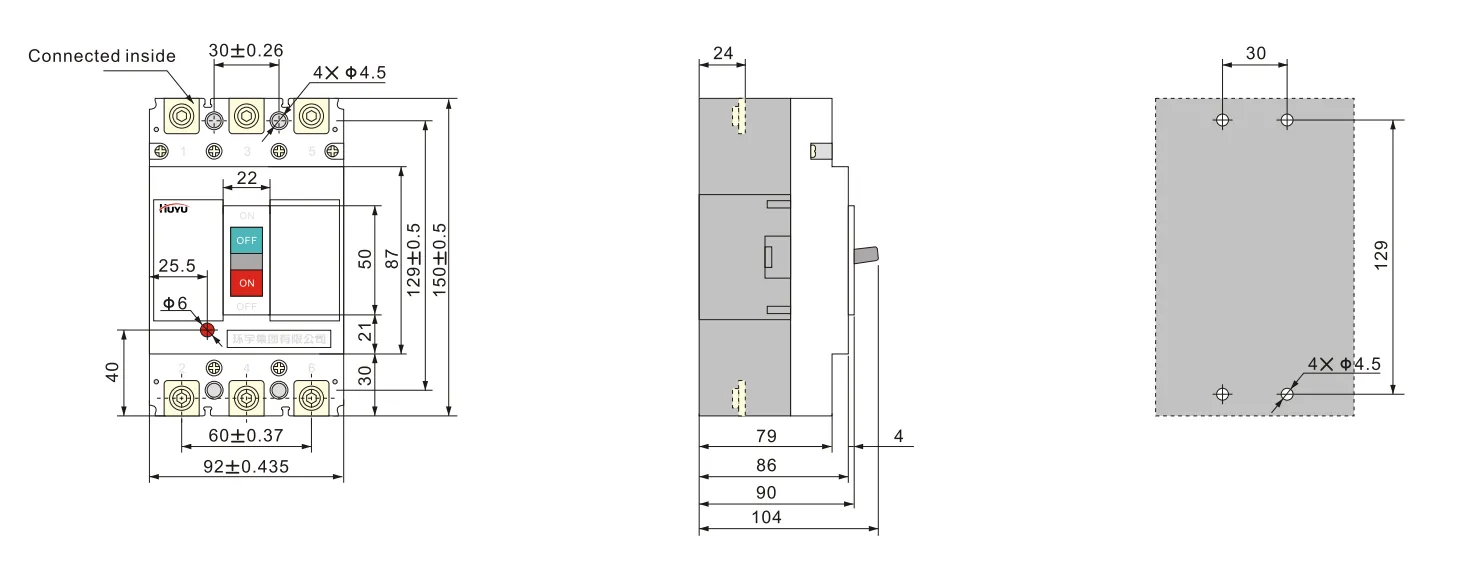
การเดินสายแบบ E สำหรับ 3PHUM8PV-125 (การเชื่อมต่อด้านหน้า)
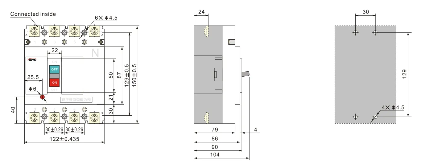
การเดินสายแบบ H สำหรับ 4P HUM8PV-125 (การเชื่อมต่อด้านหน้า)
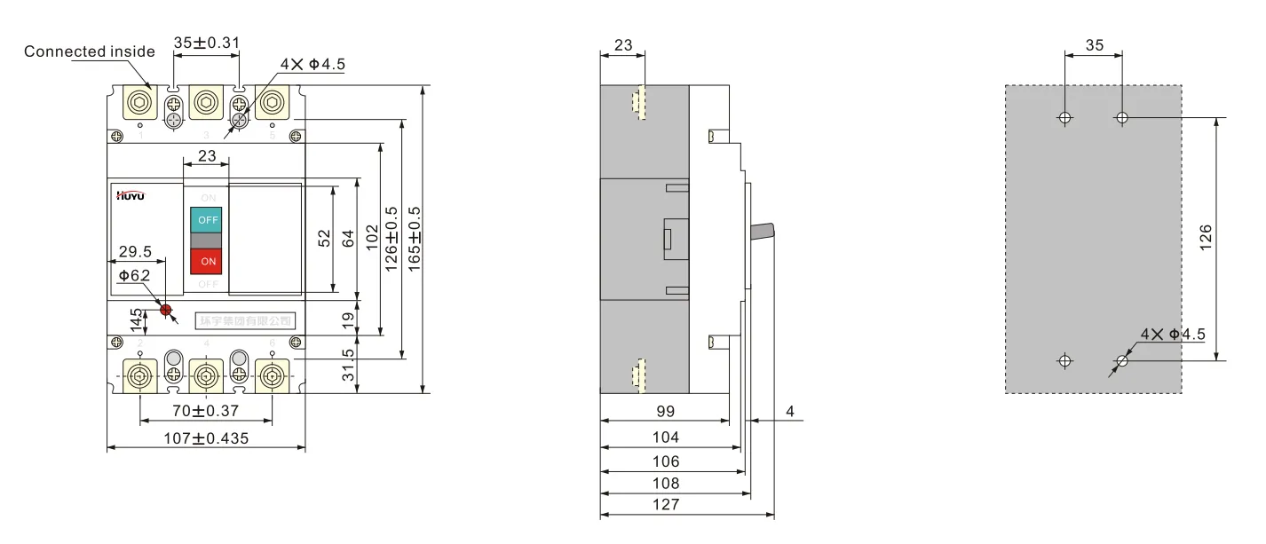
การเดินสายแบบ E สำหรับ 3P HUM8PV-250 (การเชื่อมต่อด้านหน้า)
การเดินสายแบบ H สำหรับ 4PHUM8PV-250 (การเชื่อมต่อด้านหน้า)
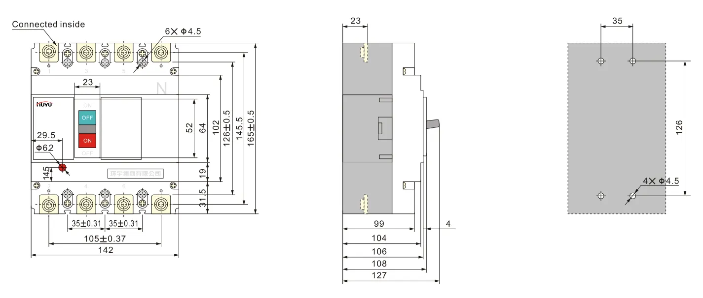
การเดินสายแบบ E สำหรับ 3PHUM8PV-400 (การเชื่อมต่อด้านหน้า)
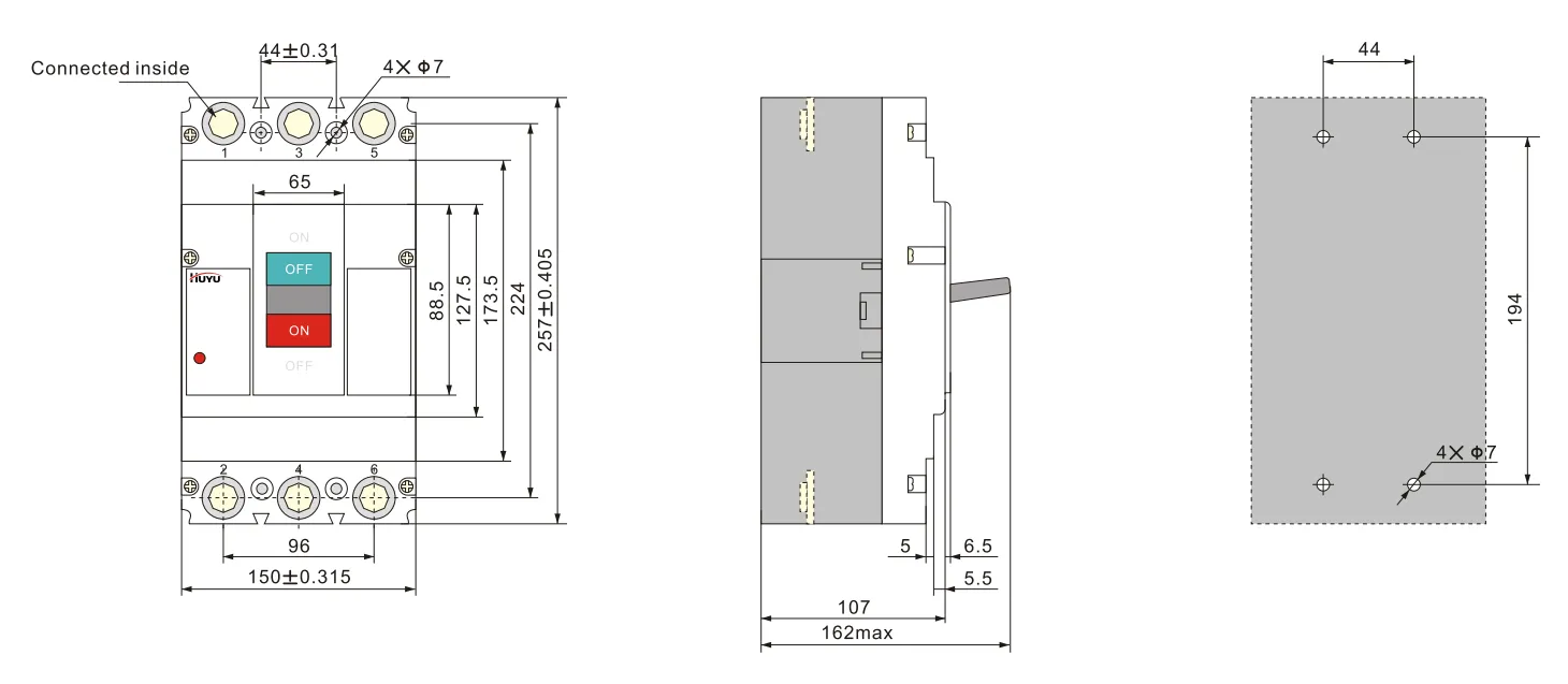
การเดินสายแบบ H สำหรับ 4P HUM8PV-400 (การเชื่อมต่อด้านหน้า)
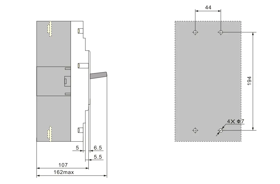
การเดินสายแบบ E สำหรับ 3PHUM8PV-630 (การเชื่อมต่อด้านหน้า)
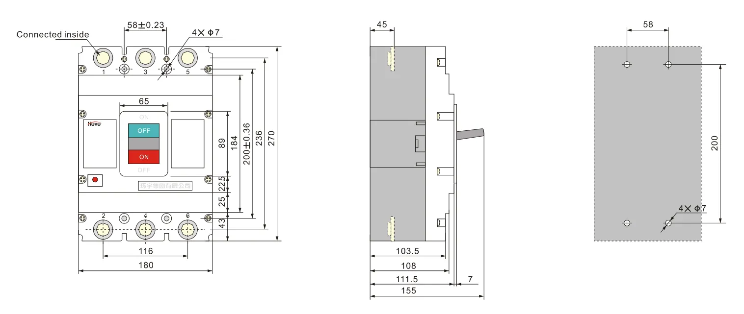
การเดินสายแบบ H สำหรับ 4P HUM8PV-630 (การเชื่อมต่อด้านหน้า)
อุปกรณ์เสริม
อุปกรณ์เสริมสามารถจัดหาได้ตามความต้องการของผู้ใช้.
พารามิเตอร์ของชันต์รีลีส:
แรงดันไฟฟ้าที่กำหนด Us: AC230V, 400V; DC 220-250V, 24-30V
เบรกเกอร์สามารถตัดได้อย่างน่าเชื่อถือที่ (70%-110%) Us และเวลาทำงานคือ 10ms-30ms.
หมายเหตุ: เมื่อใช้ชันต์รีลีส DC24V-30V ความยาวสูงสุดของสายทองแดงต้องเป็นไปตามข้อกำหนดของแผ่นที่ 6
| แรงดันไฟฟ้าควบคุมที่กำหนด Us (DC24V~30V) |
กำลังไฟฟ้าขาเข้า | ความยาวสูงสุดของสายทองแดง | |
| 5mm² | 5mm² | ||
| 100%Us | 50W | 150m | 250m |
| 85%Us | 50W | 100m | 160m |
ค่าที่กำหนดของขั้วต่อเสริมและขั้วต่อสัญญาณเตือน:
กระแสความร้อนปกติ Ith=3A; กระแสทำงานที่กำหนด le=0.79A (AC230V); le=0.47A (AC400V); le=0.15A (DC250V)
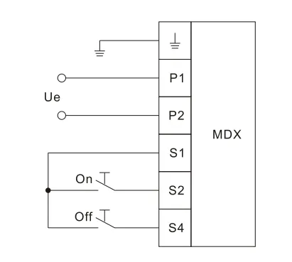
พารามิเตอร์ของกลไกการทำงานของมอเตอร์ดูที่แผ่น 7, ความสูงรวมของกลไกการทำงานของมอเตอร์ดูที่แผ่น 8 ด้านล่างเป็นแผนภาพการเดินสายของกลไกการทำงานของมอเตอร์
| ขนาดโครงสร้าง กระแสที่กำหนด le (A) | แรงดันไฟฟ้าทำงานที่กำหนด Ue(V) | กระแสเริ่มต้น (A) | เวลาทำงาน (วินาที) | ความถี่การทำงานที่กำหนด (ครั้ง/ชั่วโมง) | อายุการใช้งานทางกล (ครั้ง) |
| 125 | AC 110V~230V 50Hz DC 110V~220V |
≤0.5 | ≤0.8 | 180 | 9000 |
| 250 | |||||
| 400 | ≤2 | 120 | 5000 | ||
| 630 | 3000 |
กำลังไฟฟ้าของกลไกการทำงานของมอเตอร์ควรมีขนาดใหญ่พอเพื่อให้แรงดันไฟฟ้าที่ส่งผลกระทบเมื่อกระแสเริ่มต้นไม่ต่ำกว่า 85%Ue
| รุ่น | HUM8PV-125 | HUM8PV-250 | HUM8PV-400 | HUM8PV-630 |
| ความสูง | 170 | 199 | 230 | 246 |
ไดอะแกรมการเดินสายของกลไกการทำงานของมอเตอร์
ขนาดการติดตั้งของกลไกการทำงานด้ามหมุน ดูแผ่นที่ 9
| รุ่น | HUM8PV-125 | HUM8PV-250 | HUM8PV-400 | HUM8PV-630 |
| ขนาดการติดตั้ง (H) | 54 | 54 | 76 | 83 |
ภาพรวมและภาพวาดรูติดตั้งของด้ามจับชนิด A (สี่เหลี่ยม)
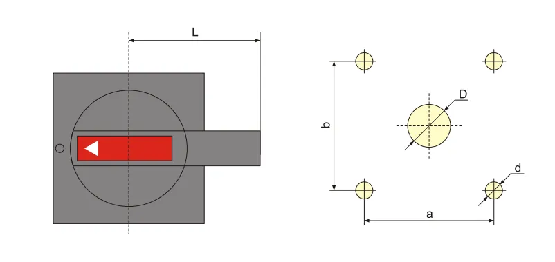
| รุ่นและสเปค | A1 | A2 |
| D | 中42 | φ 63 |
| d | 中4.5 | φ5.5 |
| a | 65 | 88 |
| b | 65 | 88 |
| L | 60 | 140 |
ภาพรวมและภาพวาดรูติดตั้งของด้ามจับชนิด B (กลม)
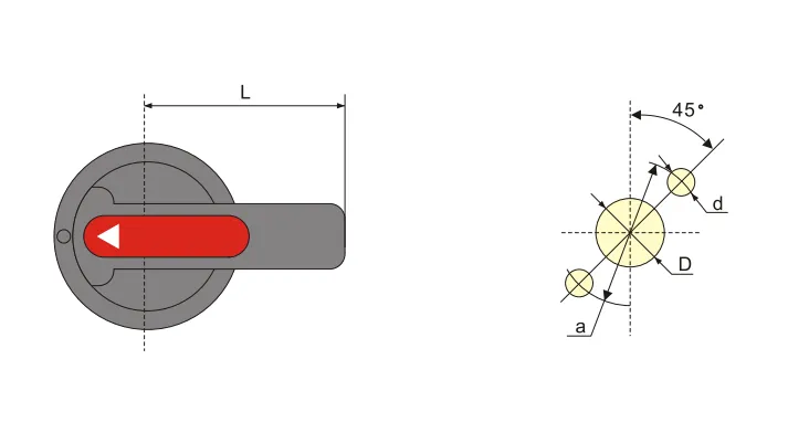
| รุ่นและสเปค | B1 | B2 | B3 |
| D | φ33 | φ33 | 中33 |
| d | 中4.5 | φ4.5 | 中4.5 |
| a | φ 53 | φ53 | φ53 |
| L | 65 | 125 | 95 |
ขนาดโดยรวมและขนาดรูติดตั้งของกลไกการทำงานด้ามหมุนแบบรวมศูนย์
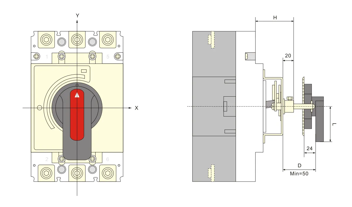
การติดตั้งและบำรุงรักษา
เรื่องที่ต้องระวังก่อนการติดตั้ง:
a. รูปลักษณ์ต้องสมบูรณ์และการทำงานไม่มีภาระผิดปกติ; ค่ากระแสไฟฟ้าที่กำหนดของเบรกเกอร์และอุปกรณ์เสริมต้องสอดคล้องกับสภาพการทำงานที่ไซต์ติดตั้ง; ไม่มีแรงกระแทกชัดเจนที่ไซต์ติดตั้งและสอดคล้องกับสภาพการทำงานปกติ
b. ควรทำการทดสอบฉนวนก่อนออกจากโรงงาน ใช้เครื่องวัด Mo 1000VDC ทำการทดสอบซ้ำก่อนติดตั้ง ระหว่างขั้วของเบรกเกอร์ ความต้านทานฉนวนระหว่างขั้วเข้าและขั้วออกเดียวกันต้องไม่ต่ำกว่า 20MΩ ในสถานะตัดวงจร
พื้นที่หน้าตัดของตัวนำต้องเกินขนาดที่กำหนดในแผ่นที่ 10 และสกรูยึดต้องขันแน่น.
ลักษณะของเบรกเกอร์และอุปกรณ์เสริมต้องตรงตามข้อกำหนดคำสั่งซื้อของเรา.
ด้ามจับเบรกเกอร์สามารถหมุนไปยังตำแหน่ง “on”, “off”, “trip” เมื่ออยู่ในตำแหน่ง “trip” ด้ามจับหมุนไปทาง “off” แล้วจึงสามารถทำงาน “on” ได้.
ก่อนเพิ่มอุปกรณ์เสริมภายใน ตัวตัดวงจรควรอยู่ในสถานะปิด.
| กระแสไฟฟ้าที่กำหนด (A) | 10 | €�20 | 25 | 32 | €�50 | 63 | 80 | 100 | 125 | 160 | €�200、225 | 250 | €�350 | 400 |
| พื้นที่หน้าตัดสายไฟ | 1.5 | 2.5 | 4 | 6 | 10 | 16 | 25 | 35 | 50 | 70 | 95 | 120 | 185 | 240 |
| กระแสไฟฟ้าที่กำหนด (A) |
พื้นที่หน้าตัดสายเคเบิล | ขนาดแท่งทองแดง | ||
| ปริมาณ | พื้นที่หน้าตัด (มม.²) | ปริมาณ | ขนาด (มม.×มม.) | |
| 500 | 2 | 150 | 2 | 30×5 |
| 630 | 2 | 185 | 2 | 40×5 |
ข้อมูลการสั่งซื้อ
ชื่อสินค้าและรุ่น
กระแสไฟฟ้าที่กำหนด, ประเภทการปล่อย, ค่าคูณกระแสตั้งค่าการปล่อยทันที
ชื่อและสเปคของอุปกรณ์เสริม
คำถามที่พบบ่อย
เบรกเกอร์แบบเคสขึ้นรูปคืออะไร?
A moulded case circuit breaker (MCCB) is a protective device enclosed in a moulded housing. It provides overcurrent and short-circuit protection for electrical circuits, with adjustable trip settings and higher breaking capacities than miniature circuit breakers.
What is a photovoltaic circuit breaker?
A photovoltaic circuit breaker is specifically designed for DC solar applications. It handles the unique characteristics of PV systems — higher DC voltages (up to 1000V or 1500V DC), non-zero-crossing DC arc extinction, and continuous load variations from solar irradiance.
What is the difference between a circuit breaker and a molded case breaker?
A “circuit breaker” is a general term for any automatic overcurrent protection device. A “molded case circuit breaker” (MCCB) is a specific type — housed in a moulded insulating casing, with higher current ratings (up to several thousand amps), adjustable trip settings, and higher breaking capacities than miniature circuit breakers (MCBs).
Which is better, ACB or MCCB?
Neither is universally “better” — they serve different applications. ACB (Air Circuit Breaker) is used for low-voltage main distribution (high current, up to 6300A), with adjustable protection and high breaking capacity. MCCB (Moulded Case Circuit Breaker) is used for branch circuit protection (up to 1600A), more compact and cost-effective for feeder circuits. Choose based on application current rating and protection requirements.