Several electrical abbreviations exist and one such abbreviation is MVA. However, few people know the exact meaning of the abbreviation before reading the nameplate of the transformer; megavolt-ampere (MVA) which is “apparent power” relates to the total power or size of the electrical circuit or system regardless of its ability to perform any useful work (i.e., the real power is referred to as MW). In general, there are two types of power defined by transformer capacity: Real Power and the so-called “apparent” power which is described in MVA. The use of the abbreviation MVA refers to measuring the development of transformer capacity in terms of electric load performance that requires MW, whereas MVA can also be used in measuring transformer capacity. This article will help to be enlightened on the meaning of MVA and how to distinguish it from kVA, MW and kW, calculate this indicator, learn what values of MVA that can be applied in transformer practice.
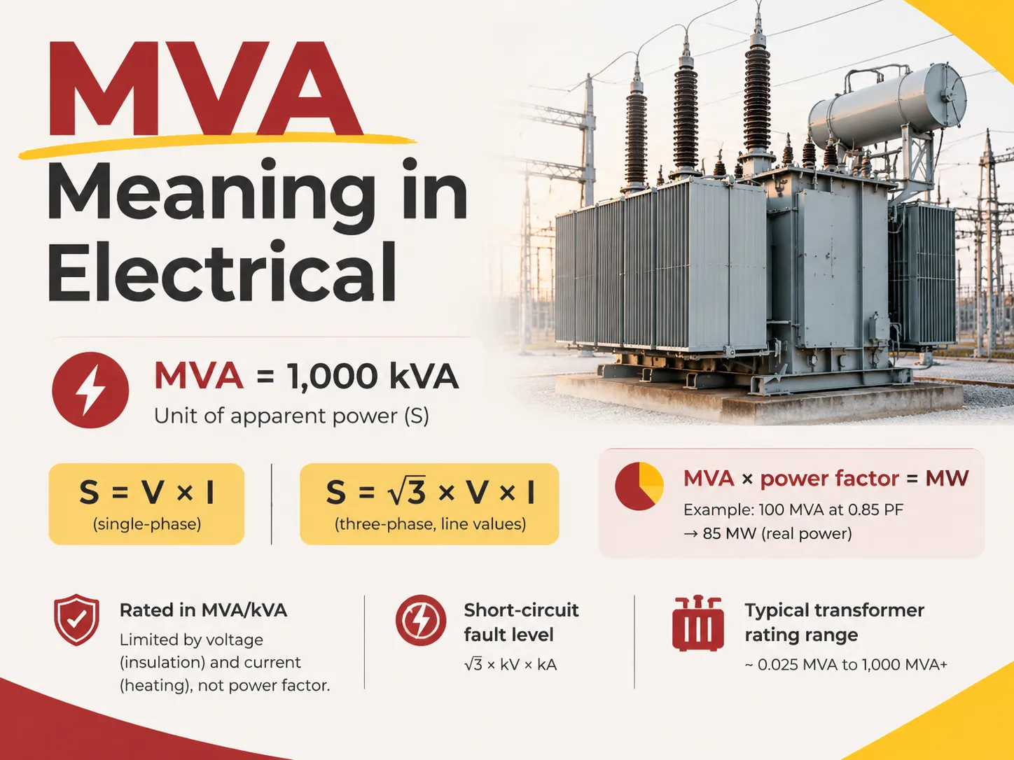
The term ‘MVA’ stands for a unit measure of apparent power whereby one MVA equals one million volt-amps (V*A) or one million volts divided by one thousand kilovolt-amperes (kVA). Apparent power, which is denoted by ‘S’ or the term volt/ampere multiplication (V*A) is the product of voltage and current in the circuit. The apparent power for both single-phase and three-phase circuits is given as follows: for single-phase, ‘S’=V*I for a single-phase circuit and ‘S’=√3(V)(I) for three-phase circuits (line voltage (V) and line current (I)). Apparent power in a circuit comprises both usable and unusable power in the circuit. In order to compute usable (active) power (MW), apparent power has to be multiplied by the Power Factor (PF) where the power factor is expressed in decimal or percentage terms showing the perspective of the actual power produced by the circuit.
What MVA Means
The abbreviations break down easily. The capital letter M represents the standard international symbol mega, which means a million. VA is the abbreviation for volt-ampere, which refers to a unit of apparent power derived from the product of voltage in volts and current in amperes. Thus, one MVA means 1,000,000 volt-amperes, meaning if a circuit runs 1,000 amperes at 1,000 volts, it has power equal to 1 MVA.
The name of the unit is written the same way as kW and MW, which has its advantages, but can also make things confusing. Though the machines in question are marked 10 MVA for a transformer and 10 MW for a generator, they are not similar devices; the first indicates the apparent power, and the latter indicates the real power. The only situation in which both numbers would indicate the same machine is when the power factor equals to 1, which practically does not happen.
MVA is mainly used in high-powered devices. For example, domestic and small commercial devices are usually measured in kVA or amperes; industrial and utility devices are measured in MVA as the numbers are large enough to make kVA impractical. There is also no lower limit for the unit, with 0.5 MVA being a typical size for a medium-sized transformer, making it a perfectly valid value. But the convention is such that MVA is used only for large equipment.
Why Apparent Power Exists
The reason electrical engineering requires a measurement other than watts is because the devices have limitations that are independent of productive work.
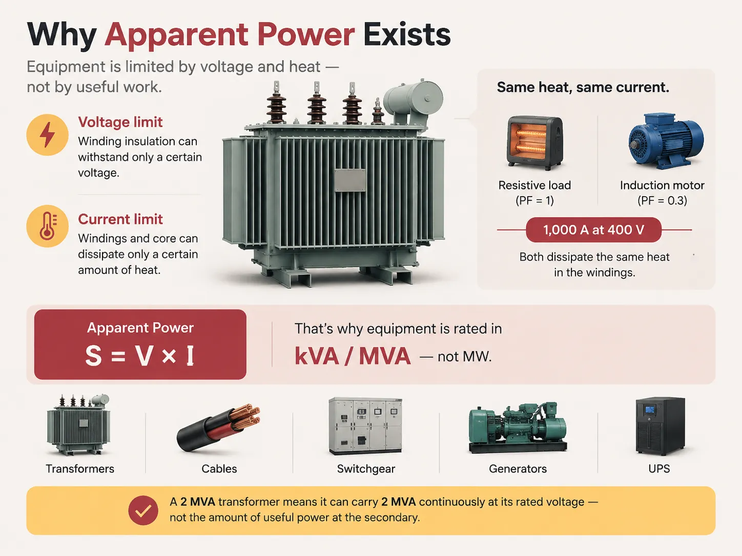
The capacity of a transformer is dictated by two physical limitations. Its winding insulation is able to withstand a specific voltage before it fails; thus, the voltage limitation is determined. Its windings and core can remove a definite quantity of heat before the temperature of its insulation exceeds the limit of the materials; therefore, the current limitation has been set. Neither limitation takes into account whether current is in phase or not with the voltage. A transformer carrying 1000 A at 400 V generates the same heat in its windings whether the load is a resistive heater with a power factor of 1 or the motor without the load with a power factor of 0.3.
This is exactly why the capacity of these devices is expressed as the product of voltage and current — apparent power — and not real power. If transformers were in MW, the device would have to provide different ratings for every power factor; therefore, the nameplate would be useless without knowing the load. Measuring transformers in MVA or kVA makes the figure the property of the device.
This reasoning may also be applied to cables, switchgear, generators, and UPS. All these devices are limited by thermal limits and insulation stress; therefore, all of them are expressed in VA or its multiples. When a buyer orders a transformer with a capacity of 2 MVA, it means that its apparent power is the power that the device will deliver continuously within temperature limits at the rated voltage.
The unit also serves as a common language across voltage levels, which is why it appears in fault calculations and protection coordination. How voltage classes are separated in practice, and why the equipment rated in MVA at one level looks nothing like its equivalent at another, is covered in the distinction between high voltage and low voltage installations.
MVA, kVA, MW, kW and MVAR Compared
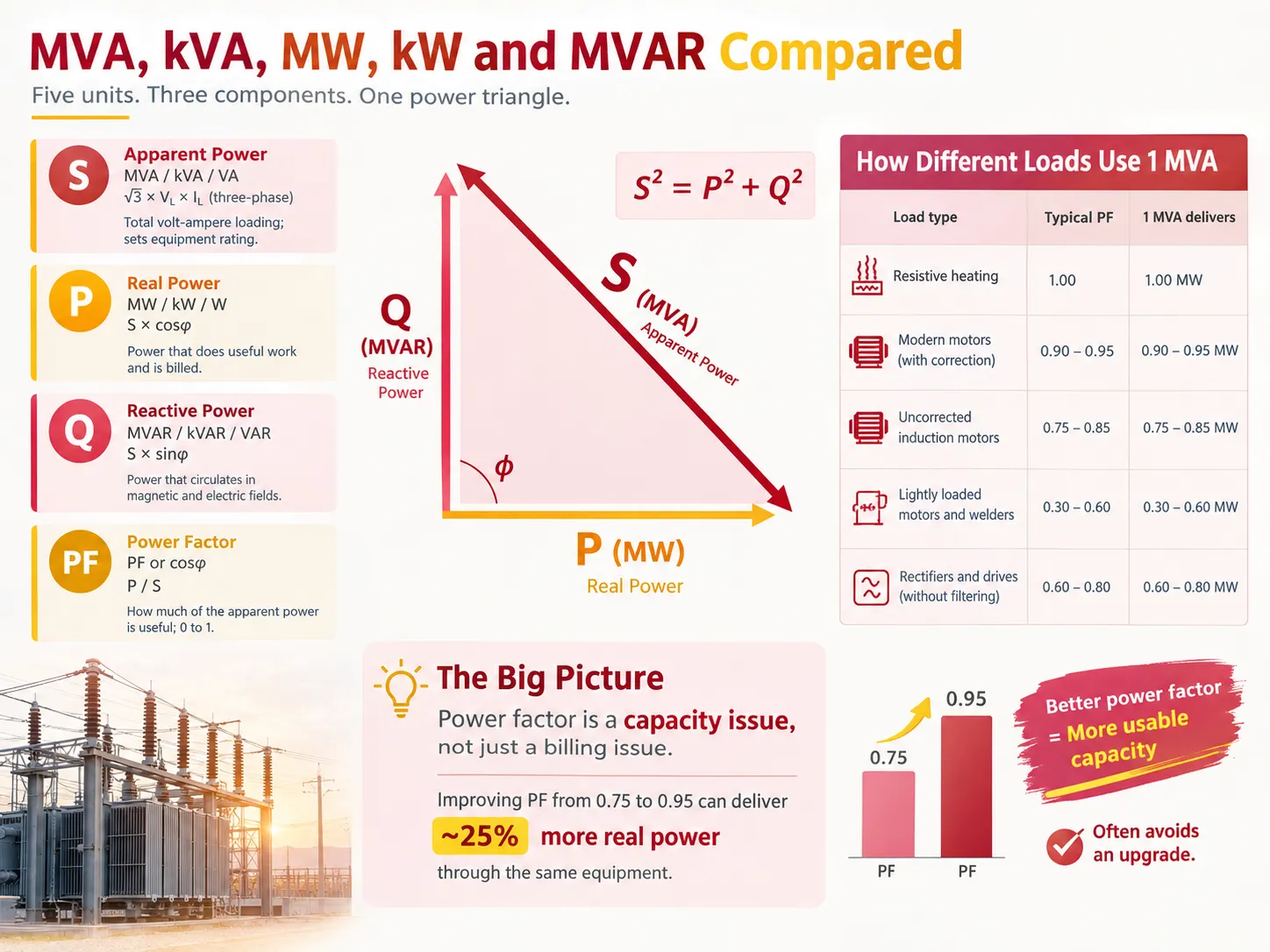
Five different units represent electrical power, and the “differences” among them reflect the difference among the three components of the power triangle referred to here.
| Unit | Quantity | Symbol | Formula | What it describes |
|---|---|---|---|---|
| MVA / kVA / VA | Apparent power | S | √3 × VL × IL (three-phase) | The total volt-ampere loading; sets equipment rating |
| MW / kW / W | Real power | P | S × cosφ | The power that does useful work and is billed |
| MVAR / kVAR / VAR | Reactive power | Q | S × sinφ | The power that circulates in magnetic and electric fields |
| Power factor | Ratio | PF or cosφ | P / S | How much of the apparent power is useful; 0 to 1 |
The relationship among the three physical quantities is determined by their geometric inter-relations; thus, they form a right triangle with apparent power represented by the hypotenuse of the geometrical figure, so the relation S2 = P2 + Q2 can be established. This formula clears most of the doubts regarding the interpretation of these units: MVA is the hypotenuse, while MW and MVAR are forming the legs of the triangle; the angle between them is known as the power factor.
| Load type | Typical power factor | 1 MVA delivers | Notes |
|---|---|---|---|
| Resistive heating | 1.00 | 1.00 MW | The theoretical maximum; rarely achieved in practice |
| Modern motors with correction | 0.90-0.95 | 0.90-0.95 MW | Typical good industrial practice |
| Uncorrected induction motors | 0.75-0.85 | 0.75-0.85 MW | Reactive power is wasted capacity from the operator’s point of view |
| Lightly loaded motors and welders | 0.30-0.60 | 0.30-0.60 MW | Poor utilisation of the equipment rating |
| Rectifiers and drives without filtering | 0.60-0.80 | 0.60-0.80 MW | Harmonic distortion may also be present |
The consequence of the fact that there is a constant relationship among these units is that power factor represents an issue of capacity rather than an issue of billing. Thus, if the power factor of something goes from 0.75 to 0.95, there will be an increase in real power transferred through the same MVA of apparatus by approximately 25 percent, which sometimes means that one won’t need to invest in additional equipment.
Readers who work primarily with smaller installations tend to meet the same relationships expressed in watts and amperes rather than in MVA, and the arithmetic is identical — the same voltage-current-power relationship scaled down, as in the calculation of wattage on a 15 amp circuit.
How to Calculate MVA
There are four computations that deal with most practical situations.
- First, from voltage and current (three-phase circuit). S = √3 × VL × IL where both the voltage and current are in line values. For 400 V three-phase circuit with the load current of 500 A, S = 1.732 × 400 × 500 = 346,410 VA or about 0.346 MVA.
- Second, from voltage and current (one-phase). S = V × I. For 230 V one-phase circuit with the load current of 100 A, S = 23,000 VA or 0.023 MVA.
- Third, from real power and power factor. S = P ÷ cosφ. For the power station with the output of 4 MW with the power factor of 0.8, S = 4 ÷ 0.8 = 5 MVA. However, if the power factor is corrected to 0.95, then S is only 4.21 MVA as this minor difference usually decides whether one transformer can accept the new load or it has to be replaced.
- Finally, from kVA. MVA = kVA ÷ 1,000. The conversion is met quite frequently while comparing a transformer rated 750 kVA with its larger counterpart of 1.5 MVA.
There are two important refinements in actual calculations. First of all, the apparent power of a load is notoriously larger than the simple sum of everyday elements owing to the fact that the motors consume a heavy magnetizing current during startup and furthermore, the loads never match their diversity factors fully. Second, keep in mind that the transformer ratings are produced for certain cooling classes and ambient temperature: a 20 MVA transformer with one cooling system may have a rating of 30 MVA with forced cooling.
MVA Ranges for Transformers
Transformer ratings can be grouped into distinctive categories, and being familiar with which one a project is in gives a lot of insight into lead times, method of procurement and pricing prior to quote delivery.
| Class | Typical MVA range | Typical voltage | Application |
|---|---|---|---|
| Small distribution | 0.025-0.5 MVA | 11-33 kV / 400 V | Pole-mounted and pad-mounted units serving a few buildings |
| Distribution | 0.5-5 MVA | 11-33 kV / 400-690 V | Commercial and light industrial supply, larger buildings |
| Medium power | 5-30 MVA | 33-132 kV | Industrial plants, substations, small generators |
| Large power | 30-100 MVA | 132-275 kV | Transmission substations, large generation connections |
| Grid power | 100-1,000+ MVA | 275-765 kV | Bulk transmission, generator step-up units |
Since MVA measures the apparent power, it follows that the actual output power of a transformer is less than the MVA rating. The output of a transformer rated 5 MVA working at a power factor of 0.85 would be equal to 4.25 MW, with the rest 0.75 MVAR being just circulated without contributing work. Thus, in sizing a transformer for a given demand of real power, the designers divide this value by the assumed power factor while putting some safety margin to allow for future increase in load, and the number MVA is not treated as an output rating.
The factor of sizing is paired with impedance, voltage ratio, class of cooling, and tap range when considering the parameters that matter when buying a transformer, but how these parameters interact, especially in terms of how the percentage impedance affects capacity and voltage regulation falls into the category of specification rather than the nameplate characteristics.Enterprise-scale installations often need to be looked at as a complete distribution architecture rather than as a set of individual machines, and the design considerations involved are set out in how distribution systems are planned for large-scale operations.
MVA and Fault Level
Another significant application of MVA in electricity is the calculation of fault level, or the power a system can provide to a short circuit. The formula is as follows.
Fault MVA = √3 × VL (in kV) × Isc (in kA)
For example, a 400 Volt network with a potential short circuit current of 25 kA has a fault level of 1.732 × 0.4 × 25 = 17.3 MVA. If we applied the same logic for 11 kV and 20 kA we would get 381 MVA. This is more than just theory since every piece of switchgear and protective equipment being installed must have an interrupting or withstand rating at least equal to the fault level at its connection point. Otherwise, a device that is not able to interrupt the fault current can be burned down rather than functioning properly. This is one of the reasons why the interrupting capacity is shown on the nameplate of every circuit breaker.
It is worth noting that the fault level is increasing along with the network expansion. The more transformers are being added in parallel, the more generation sources are connected and the higher short circuit capacity of supply is increased. All these factors make it possible for the network to have an elevated fault current even if its electric equipment remained unchanged over time.
Where a device must interrupt very large fault currents at low voltage, the answer is a purpose-built breaker rather than a larger version of a moulded-case device, and the construction differences are visible in the equipment — the HUW9 690 V 6300 A air circuit breaker is an example of how frame size, arc control and current-carrying capacity scale together when the duty is measured in hundreds of thousands of amperes of prospective fault current.
MVA in Generation and Transmission
Generators are also rated in MVA because of the same reason. The limits of the generator are set due to winding current and insulation voltage. The nameplate of the generator usually gives both the figures; for instance, it can state 150 MVA at a power factor of 0.8, producing 120 M. The MVA figure will determine the size of the unit and connection equipment while the MW figure will show what the plant can actually sell.
This rating system gives rise to a common misunderstanding. The generation capacity of “100MW” will result in the necessity of much more than 100 MVA of transformers and switchgears’ capacity because all the units, the generator itself, step-up transformer, generator circuit breaker, and connecting wires are calculated using apparent power methods.320MW will have a few constraints in terms of MVA as at 0.8 power factor it will require 125 MVA which results in a situation when designing according to MW values while applying MVA figures leads to very expensive and time-consuming adjustments in project implementation.
Transmission system utilizes MVA for determining the capacity of the transmission system; while grid connection agreements state capacity in both MVA and MW as well as power factor that should be established throughout generation. Exceeding MVA limits and working outside agreed interval of power factor values can lead to additional penalties thus making manufacturers and big consumers to monitor both values.
Using MVA in Procurement
There are four actionable steps that turn the definition into workable specification.
- Use apparent power instead of real power. The transformer is to be rated according to the apparent power needed by the load; this means dividing the expected real power by the expected power factor and allowing the margin. The method of calculating on the basis of kW alone will lead to constant under-rating of the equipment.
- Define the power factor used in the calculation. Different quotations for the same “5 MVA” transformer may involve different load power factors leading to varied real power. This assumption should be mentioned in the specification.
- State effective power rating basis. The transformer that is rated for 20 MVA when used in natural cooling with the same unit rated differently when forced cooling is applied. Identify the cooling class and ambient temperature.
- Check the fault level at the connection point. The interrupting capacity of all equipment used in service must be of the equivalent value or more than the fault MVA based on the utility’s short circuit liability. Devices that carry the appropriate rating do so under a recognised certification scheme, and the basis on which a breaker is approved is set out in the requirements behind UL 489 certification.
FAQ
What is MVA electrical?
MVA, or megavolt-ampere, is a measurement of apparent power described in terms of 1 million volt-amperes, or 1000 kVA. The calculation for this value is based on voltage and current, or the formula used for MVA is √3 x line voltage x line current in case of three-phase circuits. The indication of MVA is given for transformers, generators, cable, and switchgears since the maximum capacity of these devices is determined by value of insulation voltage and heating of windings which depend on current without taking into consideration the phase of current and voltage. MVA is used for short-circuit fault level as well.
What is a 2.5 MVA transformer?
It is a transformer which has a power of 2.5 megavolt-amperes of apparent power. This is the type of equipment that is usually used for industrial and commercial purposes, transforming a high voltage of 11 kV or 33 kV to a low one of about 400 V or 690 V. The transformer has a real power value that is lower than the value given in MVA — at a power factor equal to 0.85, this transformer can supply 2.1 MW of power with the rest of the power being reactive one. Its dimensions, mass and cooling system follow from its power. Thus, a 2.5 MVA transformer is quite a device that has its lead time and installation cost high.
What is kVA and MVA?
Both are the units of apparent power, and they differ only by a factor of a thousand; that is 1 MVA = 1,000 kVA. According to a general practice, kVA is used in case of smaller devices like distribution transformers, generators under a megawatt, uninterruptible power supply, and some time contracted capacity of an individual supply, where MVA is used as the amount grows large in case of substation transformers, generator step-up units and fault levels. The conversion is only a matter of moving the decimal, which suggests direct comparison once the scale is known.
What’s the difference between MW and MVA?
MW indicates the actual power, which makes contribution to useful work, which is calculated and charged to the customer. MVA determines the apparent power or the total volt-ampere loading of the circuit. The two are connected through the power factor MW=power factor*MVA. For instance, if a transformer of 10MVA of power factor 0.9 is used, it would provide 9MW. However, in the same scenario with the power factor 0.7 the transformer would provide only 7MW of the load. This means that enhancing the power factor will enable providing more real power by the same equipment making power factor correction a capacity improvement and a cost-saving factor.
References
- International Electrotechnical Commission — IEC 60076 Power Transformers and IEC 60027 Letter Symbols
- IEEE — Standard Definitions for Power System Quantities and Power Factor
- NFPA — National Electrical Code, Article 450 Transformers and Article 110 Short-Circuit Current Ratings
- ANSI — ANSI C57 Series Transformers, Regulators and Reactors
- U.S. Department of Energy — Power Factor and Distribution System Efficiency Guidance
Conclusion
A megavolt-ampere (abbreviated MVA) is implicated in electrical power systems as a unit of measurement for power. MVA denotes the product of voltage and current denoting electrical power to a given electrical technology or equipment. The special status enjoyed by this unit in the industry is stimulated by the constraining connection between its value and the electrical devices being based on insulation temperature and insulation voltage because they remain unaffected by the angle of lagging between the current and the voltage. That is why all energy equipment in a power system is usually rated in MVA and also kVA, and the energy output in the system is presented in terms of MW or kW. MVA is applied in three major ways: for the calculation of transformer size (delivery transformers being rated at not more than 0.025 MVA, while utility transformers can exceed 1,000 MVA), as part of the formula for calculating the fault in the system (calculation of fault in a given network is the Square Root of 3 times kV times kA), that is why application of MVA is important in order to understand capacity of the devices influencing the network.