
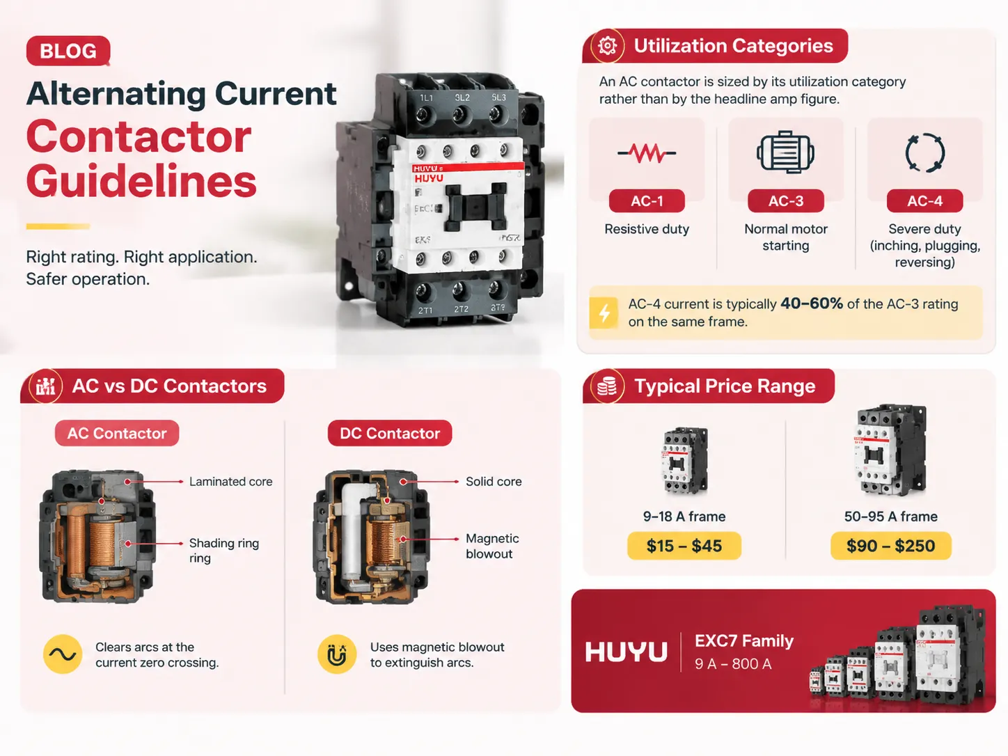
Una de las partes principales del control de motores puede llamarse fácilmente el contactor de CA. Pero vale la pena señalar que una configuración incorrecta del contactor también puede ser uno de los problemas. Por ejemplo, esos amperios que se pueden ver en el lateral del contactor proporcionan información sobre sus características de tipo resistivo. Sin embargo, si se convierte esa cifra para arrancar el motor, pueden aparecer puntos calientes en los paneles. Por lo tanto, este artículo explica qué es el contactor de CA, qué bobina posee el contactor de CA y qué lo diferencia del contactor de CC, qué categoría se usa para determinar la carga y cómo realizar el cableado, qué tipo de mantenimiento se requerirá y cuál será su precio.
En resumen, un contactor de CA funciona como un interruptor para controlar cargas de corriente alterna de forma remota. Las principales características dependen de cómo va a funcionar el contactor, no de la corriente, que es solo una de las especificaciones. Por ejemplo, AC1 indica uso en un ciclo de trabajo resistivo, AC3 indica uso para el arranque del motor, y AC4 indica uso para aplicaciones muy exigentes (por ejemplo, inversión, frenado, avance a pasos) en las que la corriente es alrededor de 40-60 % menor que AC3. Los contactores de CA y CC son tipos diferentes de interruptores: los contactores de CA tienen núcleo laminado, la tecnología de polo sombreado permite que el contactor de CA corte la corriente en el punto de cruce por cero, mientras que los contactores de CC no tienen núcleo laminado y usan soplado magnético. El precio de los contactores de CA varía de 15 a 45 para los de 9-18 A y de 90 a 250 para contactores con clasificaciones de 50-95 A. La empresa HUYU produce contactores de la serie EXC7 con corriente desde 9 A hasta 800 A.
Lo que realmente hace un contactor de CA
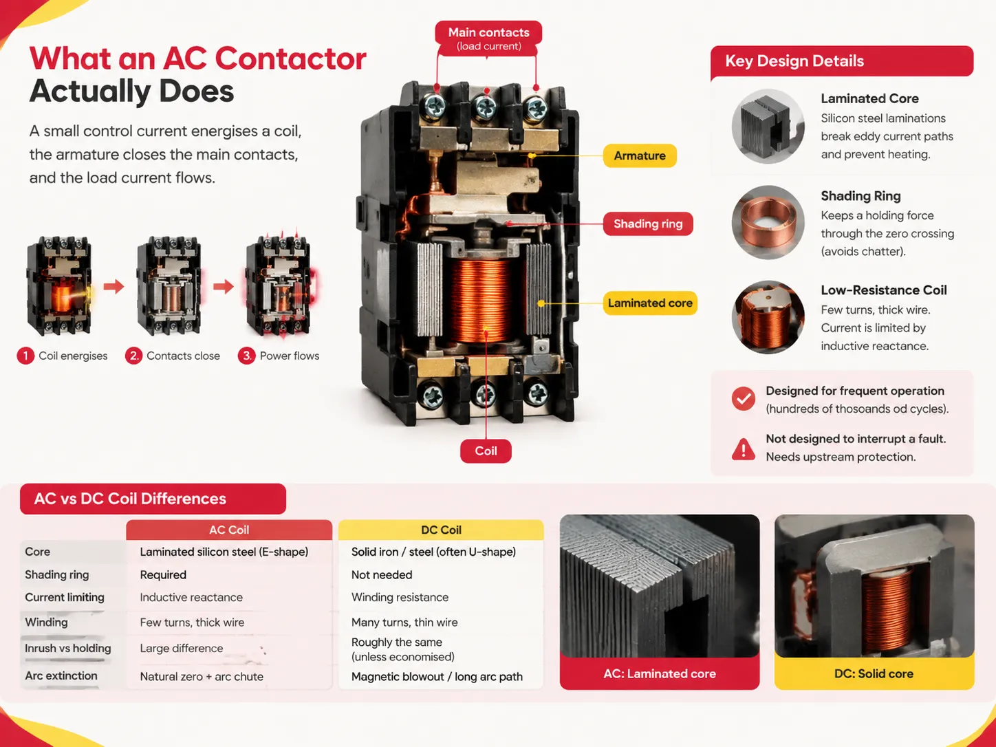
Un contactor es básicamente un interruptor operado electromagnéticamente. Cuando se activa el control, una pequeña corriente de control energiza una bobina electromagnética, que a su vez atrae un inducido, cerrando los contactos principales y permitiendo el flujo de corriente. La señal de control se elimina y el resorte abre nuevamente los contactos.
La simplicidad es el punto clave. Está diseñado para operación de muy alta frecuencia; literalmente cientos de miles de ciclos de encendido/apagado durante su vida útil, de ahí su uso generalizado en arrancadores de botón pulsador, HVAC, bombas y paneles de iluminación general. No está diseñado para dispararse ante una corriente de falla, sino que depende de un relé aguas arriba para esa función.
Cómo funcionan la bobina y el núcleo
La operación de un contactor de CA puede explicarse mediante tres características de diseño.
Núcleo laminado. Cualquier campo alterno que pasa a través de un conductor sólido induce corrientes parásitas. Si el núcleo estuviera hecho de hierro sólido, se calentaría. Por lo tanto, el diseño de un contactor de CA permite apilar láminas delgadas aislantes de acero al silicio en forma de E para interrumpir el camino de las corrientes circulantes. Esta es la respuesta a la pregunta sobre el núcleo utilizado para relés y contactores de CA: acero al silicio laminado y no hierro sólido.
El anillo de sombreado previene el ruido. A la frecuencia de 50 Hz, la corriente cruza la línea cero 100 veces por segundo, por lo que en cada cruce, la fuerza magnética desaparece. Si no se hace nada, el brazo simplemente vibrará y perderá sus contactos. La solución es un anillo de sombreado de cobre fijado en la cara del polo. El anillo de sombreado crea un retraso temporal con respecto al flujo en esa sección particular, manteniendo así la fuerza de sujeción durante todos los cruces por cero. Por lo tanto, cuando un contactor comienza a hacer un ruido fuerte, significa que el anillo de sombreado está roto o falta por otras razones.
La bobina es de baja resistencia y pocas vueltas. La bobina de CA limita su corriente mediante reactancia inductiva en lugar de resistencia y, por lo tanto, puede usar conductores gruesos y un número relativamente bajo de vueltas. Esto es de suma importancia cuando se intenta usar para operar en CC. Además, la corriente de arranque de la bobina es mucho mayor que la de mantenimiento. La unidad EXC7 tiene un consumo de potencia de 60-200 VA dependiendo del marco durante el enganche y de 9-25 VA durante el mantenimiento.
| Propiedad | Bobina de CA | Bobina de CC |
|---|---|---|
| Núcleo | Acero de silicio laminado (forma E) | Hierro / acero sólido (a menudo forma U) |
| Anillo de sombreado | Requerido | No necesario |
| Limitación de corriente | Reactancia inductiva | Resistencia del bobinado |
| Bobinado | Pocas vueltas, cable grueso | Muchas vueltas, cable delgado |
| Corriente de arranque vs mantenimiento | Gran diferencia | Aproximadamente igual (a menos que sea economizado) |
| Extinción de arco | Cero natural de corriente + cámara de arco | Soplo magnético / camino largo de arco |
Polos, amperios y tamaños de marco
Los contactores se especifican en tres dimensiones a la vez: número de polos, corriente nominal y tamaño del marco. Comprender el rango real hace que la lógica de dimensionamiento sea concreta.
La familia EXC7 va desde marcos estándar con una clasificación de 9 A a 110 A y marcos de alta corriente clasificados entre 120 A y 800 A, todos en configuración de tres polos (3P). El voltaje nominal de aislamiento es de 690 V en los marcos estándar y 1000 V en los marcos de alta corriente, con un voltaje de operación de 380/400 V o 660/690 V. La cobertura de potencia va desde 4 kW en el extremo pequeño hasta 450 kW en el marco de 800 A bajo servicio AC-4 a 690 V.
Note la diferencia en los valores de las dos columnas en la tabla a continuación. La cifra AC-1 es la corriente térmica que los contactos pueden soportar; mientras que la cifra AC-3 es lo que el dispositivo puede realmente conmutar cuando se involucra un motor. Para el marco más pequeño es 20 A, mientras que para el grande es 9 A. Dimensionar basándose en el primer número y aplicarlo a motores es el error más común en la construcción de paneles.
| Marco | AC-1 (Ith) | AC-3 a 380/400 V | AC-4 a 380/400 V | Potencia AC-3 |
|---|---|---|---|---|
| EXC7-09 | 20 A | 9 A | 5 A | 4 kW |
| EXC7-18 | 32 A | 18 A | 7 A | 5 kW |
| EXC7-32 | 50 A | 32 A | 12 A | 15 kW |
| EXC7-50 | 80 A | 50 A | 24 A | 22 kW |
| EXC7-95 | 125 A | 95 A | 44 A | 45 kW |
| EXC7-225 (armadura de alta corriente) | 275 A | 225 A | — | 110 kW (AC-4) |
| EXC7-800 (armadura de alta corriente) | 900 A | 800 A | — | 450 kW (AC-4) |
Las armaduras de alta corriente no son equivalentes ya que el fabricante proporcionará una clasificación de corriente AC-3 junto con una clasificación de potencia AC-4 en kW, lo que requiere que el usuario derive el factor de reducción a partir de las tablas relevantes de selección de armaduras en lugar de obtener una referencia cruzada clara.
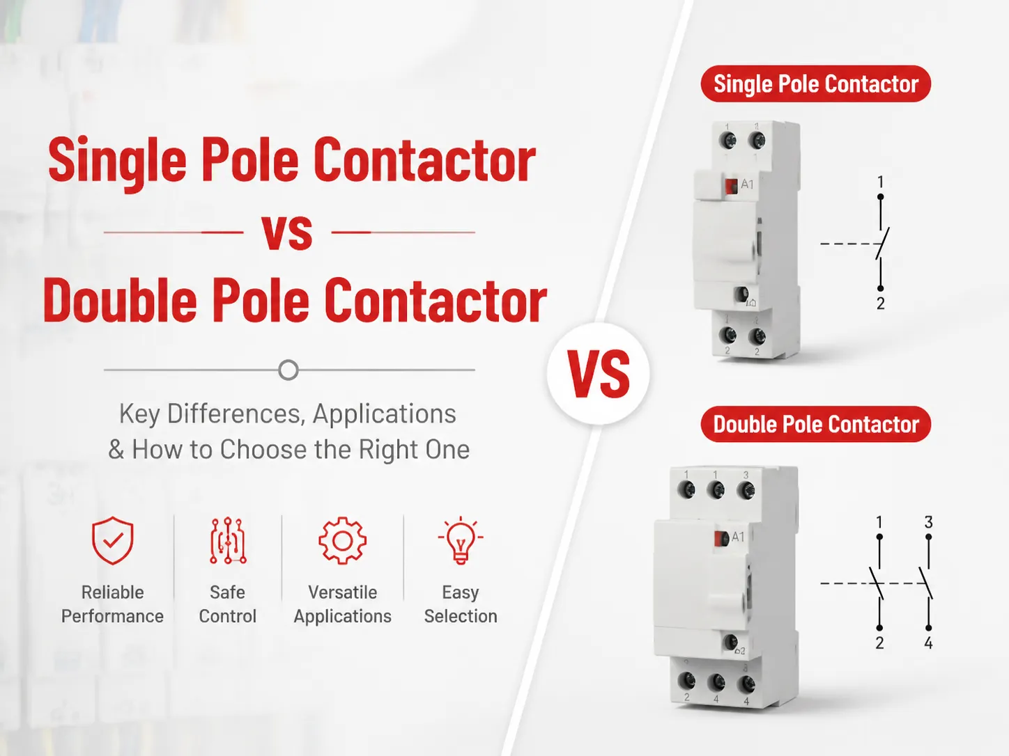
Otro factor que debe tenerse en cuenta es el número de polos. Para motores trifásicos, las unidades de tres polos son estándar; existen opciones de un polo y dos polos para ruptura de neutro, cargas monofásicas o dos circuitos separados, y es crucial entender que los dispositivos de dos polos deben conectarse de manera diferente a sus equivalentes de un polo, aunque ambos tengan el mismo número de polos.
Además, la familia de la armadura debe considerarse al buscar accesorios. Los bloques de contactos auxiliares pueden montarse en la parte superior o en el lateral, vienen con diferentes combinaciones de contactos normalmente abiertos o normalmente cerrados, contienen cabezales de retardo neumático, cubiertas contra polvo, módulos de supresión de sobretensiones y enclavamientos mecánicos para pares de inversión.
Categorías de utilización: Donde realmente ocurre el dimensionamiento del motor
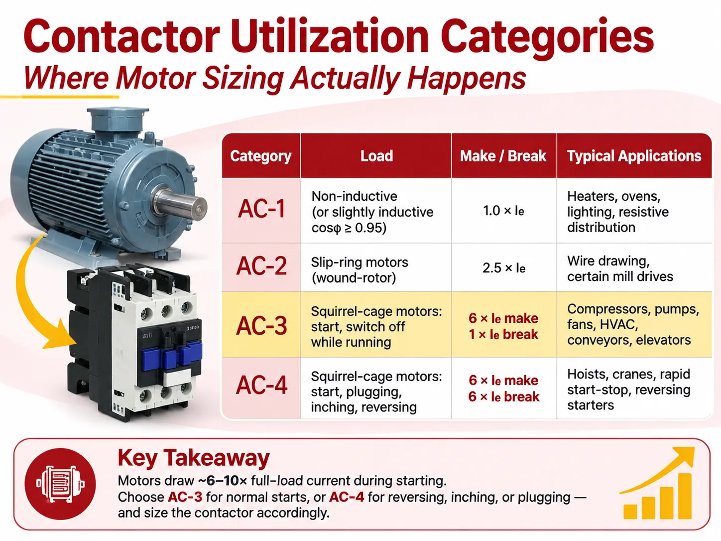
Las clasificaciones de uso de contactores están establecidas en la IEC 60947-4-1 combinando sus condiciones operativas que deben haber pasado pruebas de aprobación tipo. De varias alternativas, cuatro son las más comúnmente empleadas en la práctica, y las distinciones no son solo formales.
| Categoría | Carga | Conmutar / desconectar | Aplicaciones típicas |
|---|---|---|---|
| AC-1 | No inductivo o ligeramente inductivo (cosφ ≥ 0.95) | 0 × Ie | Calentadores, hornos, iluminación incandescente, distribución resistiva |
| AC-2 | Motores de anillo rozante (rotor bobinado) | 5 × Ie | Estirado de alambre, ciertos accionamientos antiguos de molinos |
| AC-3 | Motores jaula de ardilla: arranque, desconexión en marcha | 6 × Ie conmutar, 1 × Ie desconectar | Compresores, bombas, ventiladores, HVAC, transportadores, elevadores, mezcladores |
| AC-4 | Motores jaula de ardilla: arranque, frenado por inversión, avance lento, inversión de giro | 6 × Ie conmutar, 6 × Ie desconectar | Polipastos, grúas, arranque-parada rápida, arrancadores reversibles |
Las implicaciones en la vida real. Un motor consumirá algo así como de seis a diez veces su valor máximo de corriente mientras arranca, y el contactor tendrá que soportar esta condición. En el caso de operaciones simples de accionamiento de motor cuando solo enciende y apaga el motor mientras está en marcha, eso será AC-3; por lo tanto, se debe usar la columna AC-3. En caso de otra aplicación especial cuando el motor invierte dirección múltiples veces o se mueve a avance lento, se aplicará AC-4 y, de hecho, es necesario sobredimensionar el dispositivo porque mientras AC-4 desconecta, la corriente es seis veces mayor que la corriente normal, por lo que el dispositivo usualmente tendrá que ser sobredimensionado en uno o dos tamaños de marco y a veces tener un dispositivo de protección mayor también.
Las tablas EXC7 publican ambas columnas haciendo posible dimensionar el dispositivo correctamente. Por ejemplo, en el caso de un marco de 32 A AC-3 a 400 V la corriente es 32 A pero para AC-4 es solo 12 A. El avance lento de 12 A en un contactor de 32 A está permitido pero el avance lento de 25 A no está permitido.
Los contactores AC y DC no son intercambiables
Esta es la pregunta más frecuente, y tres razones mecánicas explican la respuesta.
El arco. La corriente alterna llega a cero dos veces en cada ciclo tras lo cual el arco pierde su energía. Si la distancia entre los puntos de contacto y el canal de arco ha alcanzado su rigidez dieléctrica, el arco no se reestablecerá. Por ello, el transformador estándar usa una pequeña distancia y un canal de arco tipo rejilla. La corriente continua no llega a cero, y por lo tanto un arco continuará funcionando hasta que sea interrumpido. Un contactor DC está equipado con bobinas de soplado magnético, guías de arco, distancias mayores y a veces cámaras herméticas o al vacío. Si un arco DC se aplica a un contactor AC, superará la vida útil del dispositivo, causando erosión significativa o soldadura de los contactos.
Bobina. Este es el tipo de falla más común. La impedancia de una bobina de CA está compuesta principalmente por reactancia inductiva, que es una función de la frecuencia. Si la bobina está conectada a CC, la frecuencia se vuelve cero, la reactancia se vuelve cero y la bobina actuará como una resistencia con muy baja resistencia. En consecuencia, la corriente aumentará de 5 a 10 veces el valor nominal, y la bobina se quemará en cuestión de segundos. El proceso opuesto no es tan notable, pero sigue siendo una falla: una bobina de CC en CA no puede operar correctamente, ya que tiene una resistencia más alta.
Núcleo. Un núcleo sólido que funciona bajo CC constante se quemará bajo CA. Además, un núcleo de CA desperdicia el material para CC. Esta es la respuesta que los ingenieros siguen equivocando: los contactores de CA usan núcleos laminados, mientras que los contactores de CC usan núcleos sólidos.
Aunque existen bobinas universales de CA/CC fabricadas con un rectificador y un regulador, todavía cuestan más y operan solo dentro de ciertos rangos de voltaje. Si la etiqueta ha especificado solo un voltaje y el tipo, asuma que es cierto. El suministro incorrecto de la bobina es una de las formas más rápidas de destruir el contactor.
Cuando necesita un contactor de CC para aplicaciones reales de conmutación DAV como baterías, cadenas solares de CC, estaciones de carga de vehículos eléctricos o accionamientos de CC. El panorama de fabricación para esa familia de productos es una cadena de suministro diferente, y esta visión general de las principales fábricas de contactores de CC es un punto de partida útil para su adquisición.
¿Es un contactor un interruptor automático?
No, y la confusión causa errores reales de diseño. Tres dispositivos diferentes realizan tres trabajos diferentes.
| Dispositivo | Trabajo | Disparo por sobrecorriente | Frecuencia de operación |
|---|---|---|---|
| Contactores | Conmutación remota de una carga | Ninguno | Muy alta (cientos de miles de ciclos) |
| Relé | Control-circuit switching and logic | Ninguno | High, but low current |
| Interruptor automático | Fault and overload interruption | Sí | Low (rare operation) |
| Thermal overload relay | Motor overload protection | Yes, via the contactor | Trips once, then resets |
| Motor circuit protector (MCP) | Short-circuit protection only | Magnetic only | Rare |
A contactor isn’t built to handle any short-circuit event, and its contacts will be damaged if it tries. A motor starter has all of the three devices working in synchronization: the contactor does the switching, the overload relay makes sure that there has been sustained overcurrent and opens the circuit of the contactor coil, the disruption of the current in the circuit happens upstream by the breaker or the fuse. That is why we need to know about the coordination Type 1 and Type 2 ratings since they tell us what will happen to the contactor when there is a short circuit with the Type 2 rating meaning that contact welding is not permitted.
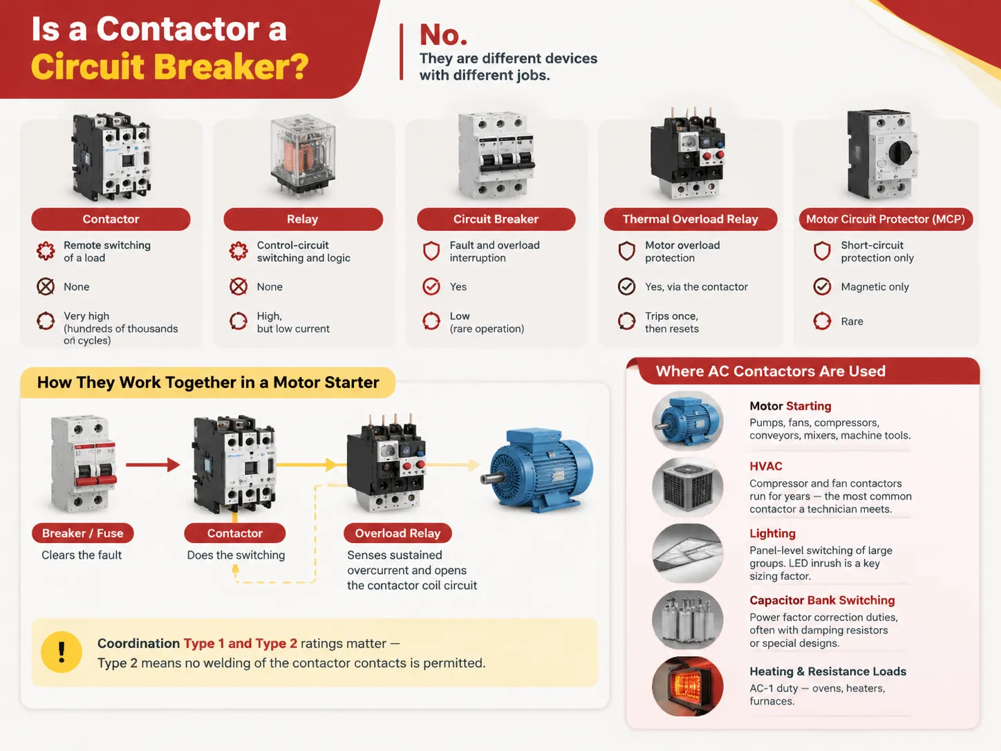
Where AC Contactors Are Used
Five categories of applications account for the majority of the industry.
- Starting of motors. This includes pumps, fans, compressors, conveyor belts, mixers, and machinery where a small motor is either operated directly or in a star-delta combination or via a soft start for larger motors as well.
- HVAC. The contactors employed in compressors and fans operate for many years and are the type of contactor most frequently seen by a technician. How this task affects the contactor after multiple starts and what failures the contactor experiences and which are caused by the refrigeration circuit must be treated separately, and the processes will be discussed in the current clarification of the operation of the contactor for HVAC equipment.
- Lighting. This is related to the control of lighting at the switchboard level where the total inrush is a proper design component due to the new LED lamp drivers.
- Switching capacitor banks. This is a function of power factor correction which involves large inrushes and utilizes damping resistors or special design contactors.
- Heating and resistive loads. This is an AC-1 function which ensures a long service life of the contactor: furnaces, heaters, stoves.
Contactors, Starters and Motor Circuits
The contactor in association with a thermal overload relay functions just like an electromagnetic starter. This combination is what is used in many three-phase motor installations.
- Direct-on-line (DOL). Only a single contactor. It has full voltage during starting. This method is simple and cheap but has its limits beyond which the electrical supply company does not approve the starting current.
- Reversing. It uses two contactors that have physical and electrical interlocks so that both can never be on at the same time. The interlock device is necessary because a control problem can cause both contactors to be closed together.
- Star-delta. This system uses three contactors and also utilizes the timer for reducing starting current while introducing some complications in the station.
- Soft Starter/VFD. This system is used at places where starting current or torque control is important, and in this case, the contactor acts as a bypass or isolation device rather being the main switching element in the circuit.
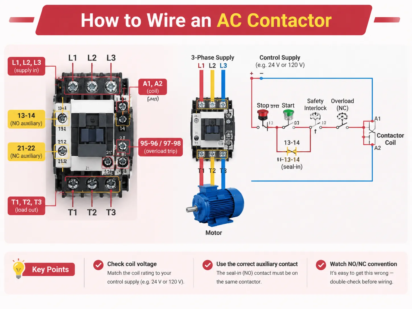
How to Wire an AC Contactor
The standard identification of each terminal should be memorised. If there is a mistake in the identification of any terminal, the contactor may falsely seem to operate but control something else.
| Terminal | Significado |
|---|---|
| L1, L2, L3 | Line side of the main poles (supply in) |
| T1, T2, T3 | Load side of the main poles (motor out) |
| A1, A2 | Coil terminals |
| 13-14 | Normally open auxiliary contact |
| 21-22 | Normally closed auxiliary contact |
| 95-96 / 97-98 | Overload relay trip contact (NC / NO) |
The wiring corresponds to its purpose. L1 to L3 correspond to power supply wires, while T1 to T3 correspond to the motor wires. The control circuit is supplied through A1 and A2 of the start button, stop button, relevant safety interlocks and normally closed contact of overload relay.
A few practical notes. First of all, test the voltage before wiring up the coil as a coil rated for 120 V will not work when connected to 24 V supply. Secondly, make sure that the AUX contact used for seal-in is actually present on the contactor on which it is sealing rather than being part of a separate relay located in the vicinity. Getting the NO/NC convention wrong is common enough to be worth a deliberate check, and the distinction is explained clearly in this comparison of normally open versus normally closed contactor wiring.
Installing and Maintaining an AC Contactor
There are two main factors that influence installation: torque and environment. In the EXC7 family of products, terminals have capacities that vary from 1 to 4 mm² in the smallest frames to 50 to 240 mm² in the largest. The fastening torque ranges from 1.2 N·m to 14 N·m. Most of the field failures of contactors are due to terminals not receiving proper torque—they end up being loose, causing heating, which leads to the failure of the terminal block.
The presence of dust covers is well justified in factories, woodworking shops, or agricultural plants since abrasive or conductive dust would wear the contacts mechanically and electrically much faster than the accessory itself would cost. Surge suppression modules also help out; when you switch a coil, the inductive effect might end up damaging the output of a PLC if not properly suppressed. AC coils often use RC snubbers or varistors while DC coils use the flyback diode or transient voltage suppressor (TVS) though the latter has a downside: simple diodes slow release timing, making them less suitable for circuits where such timing checks are required for safety.
Maintenance is not a complex process: just isolate the circuit and perform the following operations. You need to check the state of wear of contacts and pitting; see if the screws in the terminal are tight; and check the mechanical functioning of the armature and the arc chutes. Then take the readings of the coil. The coil resistance between A1 and A2 should be about tens of ohms if the coil is healthy. If the contactor does not show any odd readings, there will be a low resistance in case of a short. The voltage drop across a closed pole while the load is switched on will be in millivolts but a reading of one volt or higher indicates that the contactor is in danger of overheating.
The most helpful thing a maintenance program can do is to monitor symptoms. Будучиaanut what type of fault occurs when a contactor starts to buzz, trip overload more frequently, or hold the circuit. Collecting those early signals and acting on them is the whole basis of condition-based maintenance, and the pattern of warning signs is set out in this overview of Síntomas de falla del contactor de CA.
Ultimately, it is important to express life in quantifiable terms. Electrical life is stated in terms of operational cycles and depends on duty: the same frame that supports about a hundred thousand AC-3 operations may only be capable of a fifth under AC-4. In general, mechanical life is greater than electrical life by a factor of ten. If a contactor is replaced more often than indicated by the duty cycle, then the mistake lies in sizing and not with the equipment.
What They Cost and How to Choose a Brand
Here are the prices from US and international distributors in 2026. The gap between a famous brand and a low-cost brand is real. It is visible in the kind of contact materials used to make them, not the plastic.
| Artículo | Typical price | Notas |
|---|---|---|
| General-purpose relay, 10 A | $8–$15 | Control circuits only |
| Contactor, 9–18 A AC-3 | $15–$45 | Premium brands at the top of the band |
| Contactor, 25–40 A AC-3 | $40–$95 | Most common motor sizes |
| Contactor, 50–95 A AC-3 | $90–$250 | Frames get heavier; accessories extra |
| Contactor, 120–800 A | $250–$1,500+ | Frame size dominates the price |
| Thermal overload relay | $25–$120 | Matched to the contactor frame |
| Auxiliary contact block | $8–$25 | Per block |
| Surge suppression module | $10–$30 | RC or varistor for AC coils |
When it comes to choosing the right brand, it is no secret that major players such as Schneider, ABB, Siemens, Eaton, WEG and LS perform best when it comes to the type test results and the amount of documentation available to customers. They, however, require you to pay for it. Even though cheaper replicas of such products do exist, they are generally meant for heavier use; however, corners are being cut in the contact part, resulting in short life cycles of the devices themselves.
HUYU is in the second category, having an undeniable advantage of offering an extensive product line instead of a few types of equipment, which puts them at the bottom of the competition. The EXC7 AC contactor range covers 9 A to 800 A in one platform with the same accessory system — auxiliary blocks, delay heads, dust covers, suppressors and interlocks — and the high-current frames use a dual-coil control circuit that cuts holding power by more than 40%, which matters on a panel that runs continuously. What HUYU lacks is the decades of established customers and the native distributor network that a European brand can provide, and for a job in which the name of the brand is specified by some local utility or equipment manufacturer, this discrepancy is decisive.
Preguntas Frecuentes
What is an AC contactor used for?
The remote and continual ability to manipulate an alternating current load. This technology is mainly used for motor control, i.e., for starting or stopping three-phase motors of pumps, compressors, fans, conveyors, mixers, machine tools, and HVAC equipment. The remaining four applications include panel lighting switching, capacitor bank switching for power factor correction, resistance heating applications like ovens and furnaces, as well as general remote circuit switching when the operator has to control the load without having the manual switch that carries the full load.
¿Puede funcionar el AC sin contactor?
Definitely. A contactor is one of many ways of switching an AC load, while smaller loads are usually switched through a manual switch, relay, solid-state relay, or some drive output. If using a contactor it means one is able to switch large currents with a small control signal and at a high rate, and also take care of arc management. If the load is small, seldom switched, or managed already by current controller, the contactor might be useless or limited to isolation functions only.
¿Cuál es la diferencia entre contactor AC y DC?
The three differences are: the core – an AC contactor has a laminated silicon steel core with a shading ring whereas a DC contactor has a solid core, since the magnetic flux doesn’t change; the coil – AC coils are characterized by a low-resistance coil of only a few turns and limited by inductive reactance, while DC coils have many turns and their high resistance eliminates the effect of reactance; the function of arc control mechanism – AC uses naturally occurring zeroes of DC has to involve magnetic blowout coils, since the arc does not get extinguished by itself.
What is AC1 and AC3 contactor?
The terms are the usage categories as described in IEC 60947-4-1. AC-1 is used for either non-inductive or slightly inductive loads such as heaters and resistance loads. For AC-1 class, the only requirement for the contactor is to carry and switch the current equal to its rating. AC-3 applies to induction motors, where six times the current rating is required at the start of the motor and at switch-off operation the contactor has the same rating.When selecting the appropriate column for your application, this is one case where a 32 A rating makes sense, where AC-1 gives a rating of 50A while AC-3 gives a rating of only 32A. Thus we should be using a 32 A rated motor, not the higher number indicated on the label.
Can AC contactor be used for DC?
The normal coil does not work perfectly on the first contact or reliably on of the electrics section. An AC coil operated by DC will lose the inductive resistance, as the current will become five to ten times higher than the rated current in a second. If an AC coil is substituted with a DC coil the main contacts still will fail, as the arc chamber is designed for the arc that crosses zero in each cycle, whereas the DC arc will not break up inside the chamber.
How do I know which frame size to buy?
Consult the AC-3 column for the full-load current of this motor at its working voltage and add some margin if inching or reversing is involved; in this case, check the AC-4 column instead. Check that the appropriate accessories exist for that frame. Do not size based on the AC-1 figure or the kW figure alone, since the kW figure is declared at different voltages, hence one frame size would carry more power at 400 V and less power at 690 V.
Referencias
- UL Standards & Engagement — UL 508, Industrial Control Equipment
- NFPA — NFPA 70, National Electrical Code (motor circuits, Article 430)
- NFPA — NFPA 70E, Standard for Electrical Safety in the Workplace
- International Electrotechnical Commission — IEC 60947-4-1, contactors and motor-starters
- WEG — IEC contactor sizing, utilization categories and coordination types
Conclusión
Laminated core fitted with the shading coil that also works at low resistance using inductive reactance and arc chute working on zero-cross current basis. The understanding of these principles is essential; everything else is then easy.
The following points must be considered. First, the size should be chosen according to the application type and not based on the ampere rating so that in simple applications AC-3 is sufficient, whereas in some applications such as inverting AC-4 should be used, as this means achieving only half of the load required for the former; second, make sure that an AC coil is not being switched on from a DC supply, otherwise the coil would be burnt in a few seconds; and third, we need to understand that both terminal torque and arc chute and surge protection must be considered as maintenance items, not installation items.