
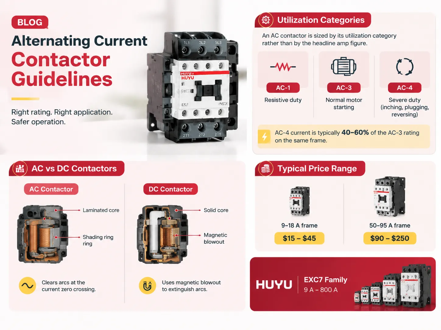
One of the main parts of motor control can easily be called the AC contactor. But it is worth noting that incorrect configuration of the contactor can also be one of the problems. For example, those Amps that one can see on the side of the contactor provide information about its resistive-type characteristics. However, if one converts that figure in order to start the engine, one may get hot spots in panels. Thus, this article explains what the AC contactor is, what the coil that the AC contactor possesses and what differentiates it from the DC contactor, what category is used to determine the load and how to perform wiring, what kind of maintenance will be required and what is going to be its price.
In summary, an AC contactor functions as a switch for controlling alternating current loads remotely. The major characteristics depend on how the contactor is going to work, not on the current, which is only one of the specifications. For example, AC1 indicates usage in a resistive duty cycle, AC3 indicates usage for starting of the motor, and AC4 indicates usage for very harsh applications (for instance, reversing, plugging, inching) at which a current is around 40-60 % less than AC3. AC and DC contactors are different sorts of switches: AC contactors have laminated core, shaded pole technology enables AC contactor to cut off the current in the zero-crossing point, while DC contactors do not have laminated core and use magnetic blowout. The price for AC contactors varies from $15 to $45 for 9-18 A ones and from $90 to $250 for contactors with 50-95 A ratings. HUYU company produces EXC7 series contactors with current going from 9 A to 800 A.
What an AC Contactor Actually Does
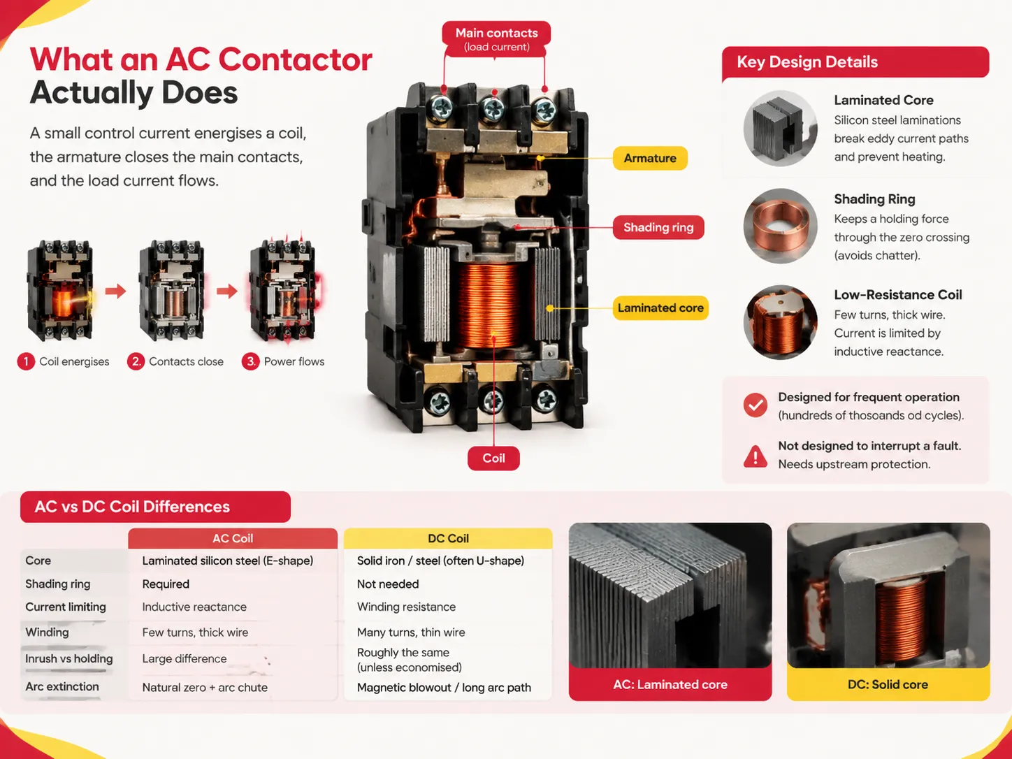
A contactor is basically an electromagnetically operated switch. When the control is switched on, a little control current will energize an electromagnet coil, this in turn pulls in an armature, thereby closing the main contacts and enabling the current to flow. The control signal is removed and the spring forces open the contacts once more.
Simplicity is the point. It is intended for very high-frequency operation; literally hundreds of thousands of on/off cycles throughout its life, hence its widespread use in push-button starters, HVACs, pumps, and general lighting panels. It is not intended to trip under fault current but instead relies on an upstream relay for that function.
How the Coil and Core Work
The operation of an AC contactor can be accounted for by means of three design characteristics.
Laminated core. Any alternating field that passes through any solid conductor induces ready-made eddy currents. If the core were made of solid iron, it would heat up. Hence, the design of an AC contactor allows for the stacking of thin insulating laminations of silicon steel of E shape so as to break the path of circulating currents. This is the answer to the question about core used for AC relay and contactors: laminated silicon steel and not solid iron.
Shading ring prevents chatter. At the frequency of 50Hz, current crosses zero-line 100 times per second, so that at every crossing, magnetic pull disappears. If nothing is done, armature will simply buzz and vibrate and thus lose its contacts. Solution is a copper shading ring fixed on the pole face. Shading ring creates time lag with respect to the flux in that particular section thus maintaining holding force all the way through zero crossings. So when a contactor starts to buzz loudly, it means that either shading ring is broken or missing due to other reasons.
Coil is low-resistance and low turn one. The AC coil limits its current by means of inductive reactance rather than resistance and may therefore use thick conductors and relatively low number of turns. This is of utmost importance when one attempts to use it to operate on DC. Moreover, coils inrush is much higher than holding. The EXC7 unit has the power draw of 60-200 VA depending on the frame during pull-in and 9-25 VA during holding.
| Property | AC coil | DC coil |
|---|---|---|
| Core | Laminated silicon steel (E-shape) | Solid iron / steel (often U-shape) |
| Shading ring | Required | Not needed |
| Current limiting | Inductive reactance | Winding resistance |
| Winding | Few turns, thick wire | Many turns, thin wire |
| Inrush vs holding | Large difference | Roughly the same (unless economised) |
| Arc extinction | Natural current zero + arc chute | Magnetic blowout / long arc path |
Poles, Amps and Frame Sizes
Contactors are specified across three dimensions at once: pole count, current rating and frame size. Getting the flavour of a real range makes the sizing logic concrete.
The EXC7 family runs from standard frames rated 9 A to 110 A and high current frames rated between 120 A and 800 A, all in three-pole (3P) configuration. Rated insulation voltage is 690 V on the standard frames and 1000 V on the high-current frames, with an operating voltage of 380/400 V or 660/690 V. Power coverage runs from 4 kW at the small end to 450 kW on the 800 A frame under AC-4 duty at 690 V.
Note the dissimilarity in the values of the two columns in the table below. The AC-1 figure is the thermal current the contacts can carry; while the AC-3 figure is what the device can actually switch when a motor is involved. For the smallest frame that is 20 A, whereas for the large one, it is 9 A. Sizing off the first number and applying it to motors factored in is the single most common error in panel building.
| Frame | AC-1 (Ith) | AC-3 at 380/400 V | AC-4 at 380/400 V | AC-3 power |
|---|---|---|---|---|
| EXC7-09 | 20 A | 9 A | 3.5 A | 4 kW |
| EXC7-18 | 32 A | 18 A | 7.7 A | 7.5 kW |
| EXC7-32 | 50 A | 32 A | 12 A | 15 kW |
| EXC7-50 | 80 A | 50 A | 24 A | 22 kW |
| EXC7-95 | 125 A | 95 A | 44 A | 45 kW |
| EXC7-225 (high-current frame) | 275 A | 225 A | — | 110 kW (AC-4) |
| EXC7-800 (high-current frame) | 900 A | 800 A | — | 450 kW (AC-4) |
The high-current frames are not equivalent as the manufacturer will provide an AC-3 current rating along with an AC-4 power rating in kW, which requires the user to derive the derating factor from the relevant frame selection tables instead of coming up with a clear cross-reference.
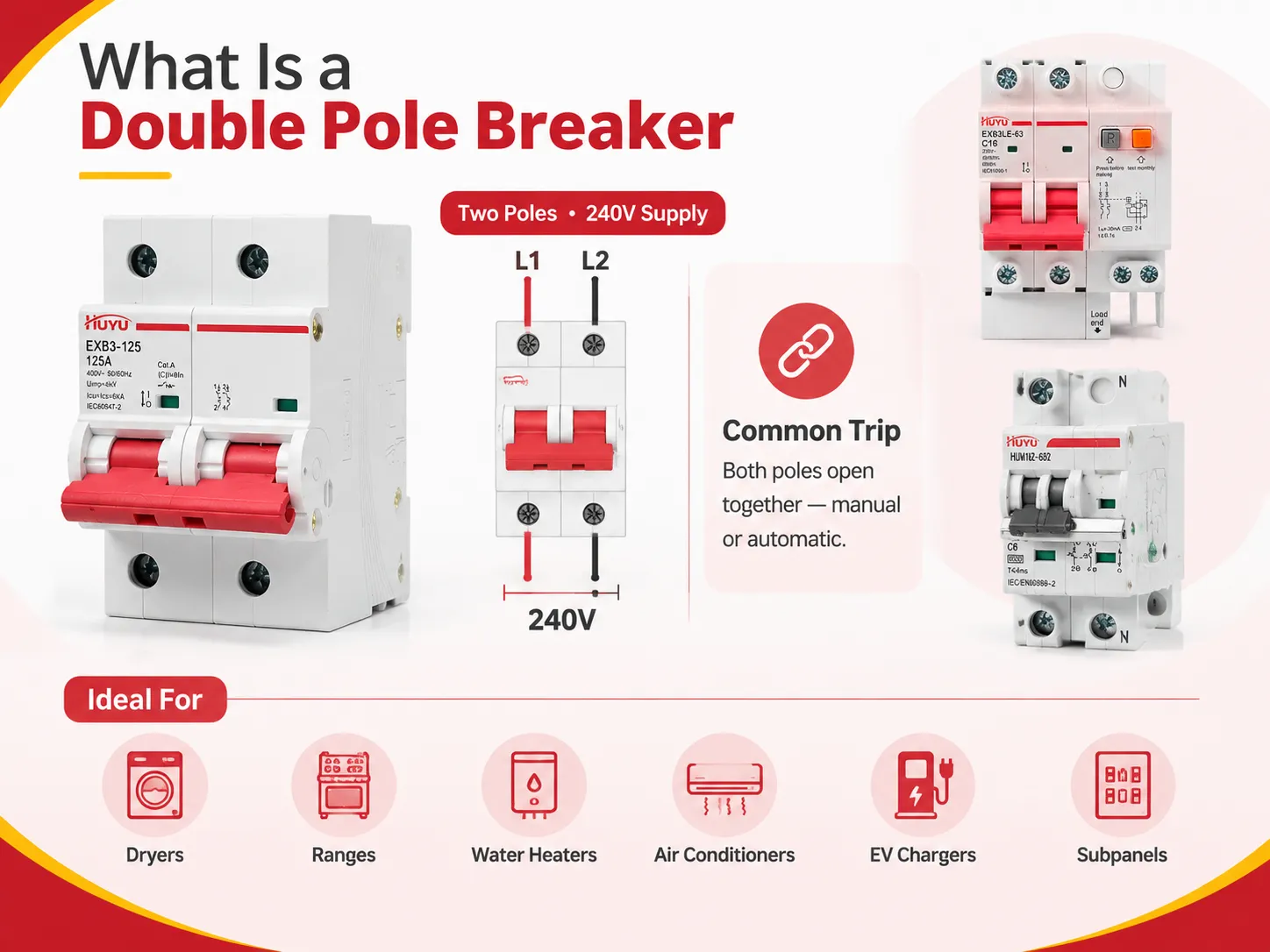
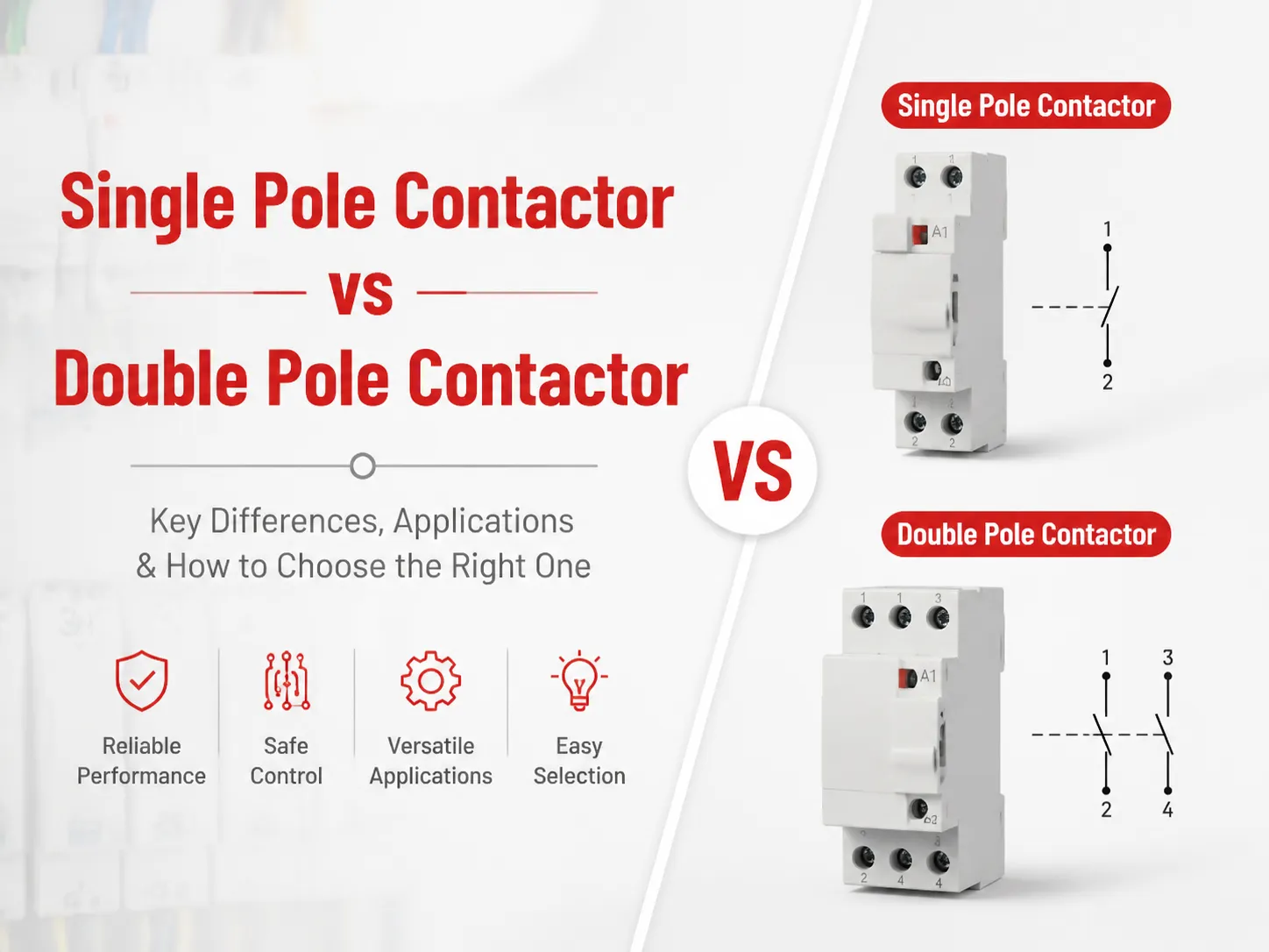
Another factor that must be taken into consideration is pole count. For three-phase motors, three-pole units are standard; single-pole and double-pole options exist for neutral breakage, single-phase loads, or two separate circuits, and it is crucial to understand that double-pole devices must be connected differently than their one-pole counterparts, although both have the same pole count.
In addition, the family of the frame must be taken into account when looking for accessories. Auxiliary contact blocks can be top-mounted or side-mounted, come with different combinations of normally open or normally closed contacts, contain pneumatic time-delay heads, dust covers, surge suppression modules, and mechanical interlocks for reversing pairs.
Utilization Categories: Where Motor Sizing Actually Happens
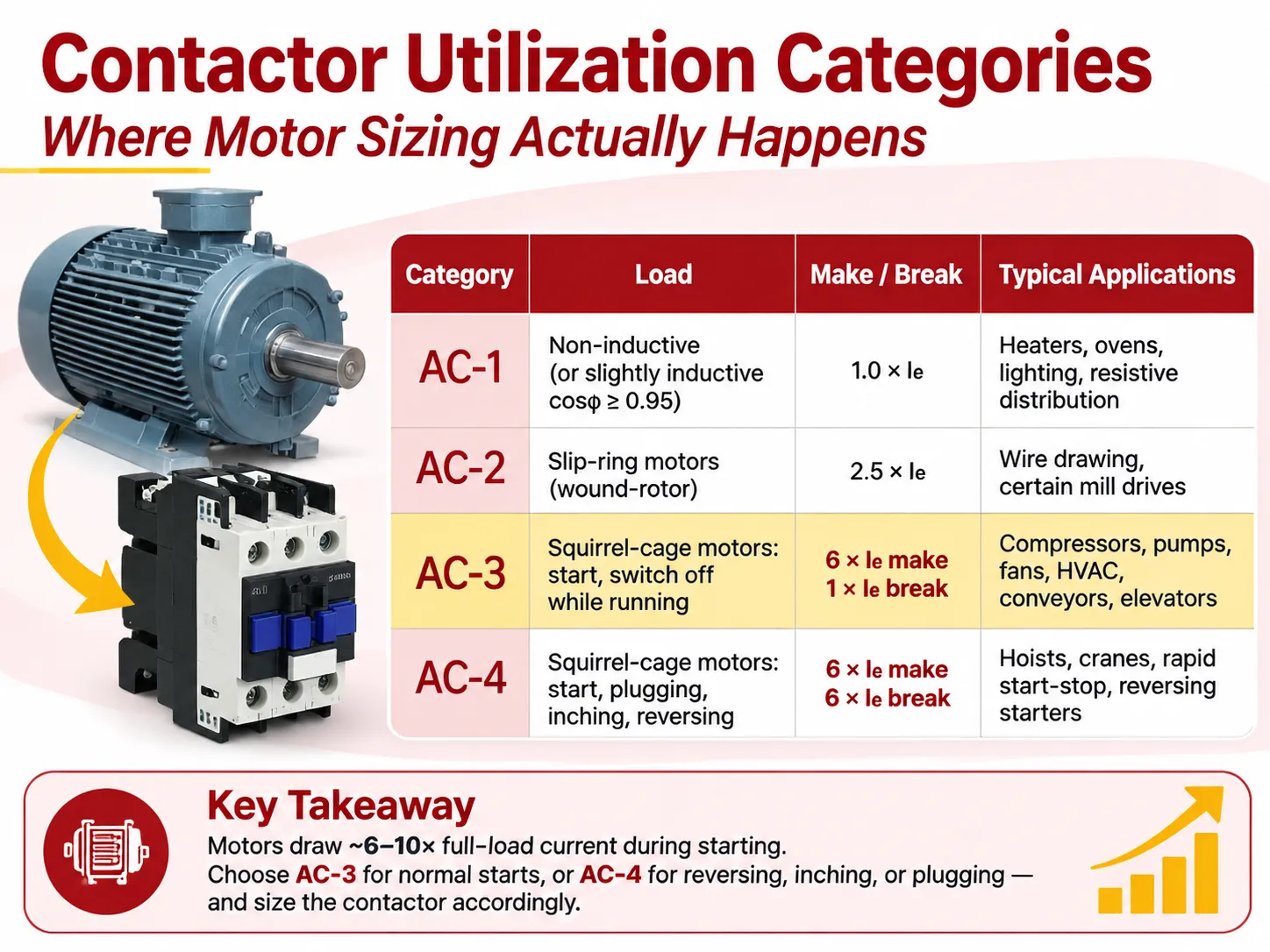
Contactor usage classifications are established in IEC 60947-4-1 by combining their operational conditions that must have gone through type approval tests. Out of various alternatives, four are most commonly employed in practices, and the distinctions are not only formal.
| Category | Load | Make / break | Typical applications |
|---|---|---|---|
| AC-1 | Non-inductive or slightly inductive (cosφ ≥ 0.95) | 1.0 × Ie | Heaters, ovens, incandescent lighting, resistive distribution |
| AC-2 | Slip-ring (wound-rotor) motors | 2.5 × Ie | Wire drawing, certain legacy mill drives |
| AC-3 | Squirrel-cage motors: start, switch off while running | 6 × Ie make, 1 × Ie break | Compressors, pumps, fans, HVAC, conveyors, elevators, mixers |
| AC-4 | Squirrel-cage motors: start, plugging, inching, reversing | 6 × Ie make, 6 × Ie break | Hoists, cranes, rapid start-stop, reversing starters |
The implications in real life. A motor will pull something like six to ten times its maximum current value while it starts, and the contactor will have to withstand this condition. In the case of simple motor driving operations when it only switches the motor on and off while it is running, that will be AC-3; so, AC-3 column has to be used. In case of another special application when the motor reverses directions multiple times or is being inched, AC-4 will apply and actually, one needs to upsize the device because while AC-4 breaks, the current is six times higher than the normal current, so the device will usually have to be upscaled for one or two frames and sometimes have a larger protective device as well.
EXC7 tables publish both of the columns making it possible to size the device properly. For example, in case of 32 A frame AC-3 at 400 V the current is 32 A but for AC-4 it is only 12 A. Inching 12 A on contactor 32 A is allowed but inching 25 A is not allowed.
AC and DC Contactors Are Not Interchangeable
This is the most frequently asked question, and three mechanical reasons explain the answer.
The arc. The alternating current reaches zero twice every cycle after which the arc loses its energy. If the gap between the contact points and the arc chute has gained its dielectric strength, the arc will not strike again. Thus, the standard transformer uses a small gap and a grid-type arc chute. The direct current does not reach zero, and hence an arc will continue doing its job until it is interrupted. A DC contactor is equipped with magnetic blowout coils, arc runners, larger gaps, and sometimes airtight or vacuums. If a DC arc is applied to an AC contactor, it will outlive the device, leading to significant erosion or welding of the contacts.
Coil. This is the most common type of failure. The impedance of an AC coil is mainly made up of inductive reactance, which is a function of frequency. If the coil is connected to DC, the frequency becomes zero, reactance becomes zero, and the coil will act as a resistor with very low resistance. Consequently, the current will rise to 5-10 times the rated value, and the coil will burn out in a matter of seconds. The opposite process is not so remarkable, but it is a failure anyway: a DC coil on AC cannot operate properly, as it has a higher resistance.
Core. A solid core that works under steady DC will burn under AC. In addition, an AC core wastes the material for DC. This is the answer that engineers keep on getting wrong: AC contactors use laminated cores, while DC contactors use solid ones.
While there are universal AC/DC coils made with a rectifier and a regulator, they still cost more and operate only within certain voltage ranges. If the label has specified only one voltage and the type, assume that it is true. The wrong coil supply is among the fastest ways to destroy the contactor.
When you need a DC contactor for actual DAV switching applications like batteries, solar DC strings, EV charging stations, or DC drives.The manufacturing landscape for that product family is a different supply chain, and this overview of the leading DC contactor factories is a useful starting point for sourcing one.
Is a Contactor a Circuit Breaker?
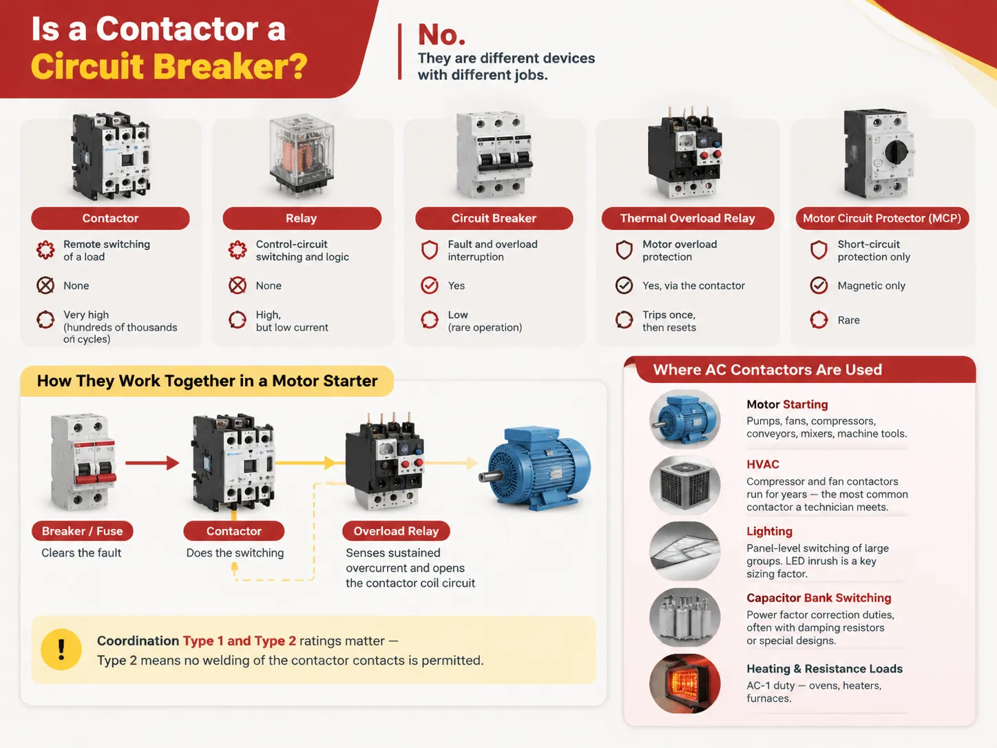
No, and the confusion causes real design errors. Three different devices do three different jobs.
| Device | Job | Overcurrent trip | Operation frequency |
|---|---|---|---|
| Contactor | Remote switching of a load | None | Very high (hundreds of thousands of cycles) |
| Relay | Control-circuit switching and logic | None | High, but low current |
| Circuit breaker | Fault and overload interruption | Yes | Low (rare operation) |
| Thermal overload relay | Motor overload protection | Yes, via the contactor | Trips once, then resets |
| Motor circuit protector (MCP) | Short-circuit protection only | Magnetic only | Rare |
A contactor isn’t built to handle any short-circuit event, and its contacts will be damaged if it tries. A motor starter has all of the three devices working in synchronization: the contactor does the switching, the overload relay makes sure that there has been sustained overcurrent and opens the circuit of the contactor coil, the disruption of the current in the circuit happens upstream by the breaker or the fuse. That is why we need to know about the coordination Type 1 and Type 2 ratings since they tell us what will happen to the contactor when there is a short circuit with the Type 2 rating meaning that contact welding is not permitted.
Where AC Contactors Are Used
Five categories of applications account for the majority of the industry.
- Starting of motors. This includes pumps, fans, compressors, conveyor belts, mixers, and machinery where a small motor is either operated directly or in a star-delta combination or via a soft start for larger motors as well.
- HVAC. The contactors employed in compressors and fans operate for many years and are the type of contactor most frequently seen by a technician. How this task affects the contactor after multiple starts and what failures the contactor experiences and which are caused by the refrigeration circuit must be treated separately, and the processes will be discussed in the current clarification of the operation of the contactor for HVAC equipment.
- Lighting. This is related to the control of lighting at the switchboard level where the total inrush is a proper design component due to the new LED lamp drivers.
- Switching capacitor banks. This is a function of power factor correction which involves large inrushes and utilizes damping resistors or special design contactors.
- Heating and resistive loads. This is an AC-1 function which ensures a long service life of the contactor: furnaces, heaters, stoves.
Contactors, Starters and Motor Circuits
The contactor in association with a thermal overload relay functions just like an electromagnetic starter. This combination is what is used in many three-phase motor installations.
- Direct-on-line (DOL). Only a single contactor. It has full voltage during starting. This method is simple and cheap but has its limits beyond which the electrical supply company does not approve the starting current.
- Reversing. It uses two contactors that have physical and electrical interlocks so that both can never be on at the same time. The interlock device is necessary because a control problem can cause both contactors to be closed together.
- Star-delta. This system uses three contactors and also utilizes the timer for reducing starting current while introducing some complications in the station.
- Soft Starter/VFD. This system is used at places where starting current or torque control is important, and in this case, the contactor acts as a bypass or isolation device rather being the main switching element in the circuit.
How to Wire an AC Contactor
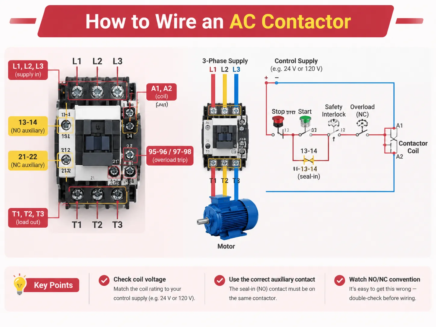
The standard identification of each terminal should be memorised. If there is a mistake in the identification of any terminal, the contactor may falsely seem to operate but control something else.
| Terminal | Meaning |
|---|---|
| L1, L2, L3 | Line side of the main poles (supply in) |
| T1, T2, T3 | Load side of the main poles (motor out) |
| A1, A2 | Coil terminals |
| 13-14 | Normally open auxiliary contact |
| 21-22 | Normally closed auxiliary contact |
| 95-96 / 97-98 | Overload relay trip contact (NC / NO) |
The wiring corresponds to its purpose. L1 to L3 correspond to power supply wires, while T1 to T3 correspond to the motor wires. The control circuit is supplied through A1 and A2 of the start button, stop button, relevant safety interlocks and normally closed contact of overload relay.
A few practical notes. First of all, test the voltage before wiring up the coil as a coil rated for 120 V will not work when connected to 24 V supply. Secondly, make sure that the AUX contact used for seal-in is actually present on the contactor on which it is sealing rather than being part of a separate relay located in the vicinity. Getting the NO/NC convention wrong is common enough to be worth a deliberate check, and the distinction is explained clearly in this comparison of normally open versus normally closed contactor wiring.
Installing and Maintaining an AC Contactor
There are two main factors that influence installation: torque and environment. In the EXC7 family of products, terminals have capacities that vary from 1 to 4 mm² in the smallest frames to 50 to 240 mm² in the largest. The fastening torque ranges from 1.2 N·m to 14 N·m. Most of the field failures of contactors are due to terminals not receiving proper torque—they end up being loose, causing heating, which leads to the failure of the terminal block.
The presence of dust covers is well justified in factories, woodworking shops, or agricultural plants since abrasive or conductive dust would wear the contacts mechanically and electrically much faster than the accessory itself would cost. Surge suppression modules also help out; when you switch a coil, the inductive effect might end up damaging the output of a PLC if not properly suppressed. AC coils often use RC snubbers or varistors while DC coils use the flyback diode or transient voltage suppressor (TVS) though the latter has a downside: simple diodes slow release timing, making them less suitable for circuits where such timing checks are required for safety.
Maintenance is not a complex process: just isolate the circuit and perform the following operations. You need to check the state of wear of contacts and pitting; see if the screws in the terminal are tight; and check the mechanical functioning of the armature and the arc chutes. Then take the readings of the coil. The coil resistance between A1 and A2 should be about tens of ohms if the coil is healthy. If the contactor does not show any odd readings, there will be a low resistance in case of a short. The voltage drop across a closed pole while the load is switched on will be in millivolts but a reading of one volt or higher indicates that the contactor is in danger of overheating.
The most helpful thing a maintenance program can do is to monitor symptoms. Будучиaanut what type of fault occurs when a contactor starts to buzz, trip overload more frequently, or hold the circuit. Collecting those early signals and acting on them is the whole basis of condition-based maintenance, and the pattern of warning signs is set out in this overview of AC contactor failure symptoms.
Ultimately, it is important to express life in quantifiable terms. Electrical life is stated in terms of operational cycles and depends on duty: the same frame that supports about a hundred thousand AC-3 operations may only be capable of a fifth under AC-4. In general, mechanical life is greater than electrical life by a factor of ten. If a contactor is replaced more often than indicated by the duty cycle, then the mistake lies in sizing and not with the equipment.
What They Cost and How to Choose a Brand
Here are the prices from US and international distributors in 2026. The gap between a famous brand and a low-cost brand is real. It is visible in the kind of contact materials used to make them, not the plastic.
| Item | Typical price | Notes |
|---|---|---|
| General-purpose relay, 10 A | $8–$15 | Control circuits only |
| Contactor, 9–18 A AC-3 | $15–$45 | Premium brands at the top of the band |
| Contactor, 25–40 A AC-3 | $40–$95 | Most common motor sizes |
| Contactor, 50–95 A AC-3 | $90–$250 | Frames get heavier; accessories extra |
| Contactor, 120–800 A | $250–$1,500+ | Frame size dominates the price |
| Thermal overload relay | $25–$120 | Matched to the contactor frame |
| Auxiliary contact block | $8–$25 | Per block |
| Surge suppression module | $10–$30 | RC or varistor for AC coils |
When it comes to choosing the right brand, it is no secret that major players such as Schneider, ABB, Siemens, Eaton, WEG and LS perform best when it comes to the type test results and the amount of documentation available to customers. They, however, require you to pay for it. Even though cheaper replicas of such products do exist, they are generally meant for heavier use; however, corners are being cut in the contact part, resulting in short life cycles of the devices themselves.
HUYU is in the second category, having an undeniable advantage of offering an extensive product line instead of a few types of equipment, which puts them at the bottom of the competition. The EXC7 AC contactor range covers 9 A to 800 A in one platform with the same accessory system — auxiliary blocks, delay heads, dust covers, suppressors and interlocks — and the high-current frames use a dual-coil control circuit that cuts holding power by more than 40%, which matters on a panel that runs continuously. What HUYU lacks is the decades of established customers and the native distributor network that a European brand can provide, and for a job in which the name of the brand is specified by some local utility or equipment manufacturer, this discrepancy is decisive.
FAQ
What is an AC contactor used for?
The remote and continual ability to manipulate an alternating current load. This technology is mainly used for motor control, i.e., for starting or stopping three-phase motors of pumps, compressors, fans, conveyors, mixers, machine tools, and HVAC equipment. The remaining four applications include panel lighting switching, capacitor bank switching for power factor correction, resistance heating applications like ovens and furnaces, as well as general remote circuit switching when the operator has to control the load without having the manual switch that carries the full load.
Can AC work without contactor?
Definitely. A contactor is one of many ways of switching an AC load, while smaller loads are usually switched through a manual switch, relay, solid-state relay, or some drive output. If using a contactor it means one is able to switch large currents with a small control signal and at a high rate, and also take care of arc management. If the load is small, seldom switched, or managed already by current controller, the contactor might be useless or limited to isolation functions only.
What is the difference between AC and DC contactor?
The three differences are: the core – an AC contactor has a laminated silicon steel core with a shading ring whereas a DC contactor has a solid core, since the magnetic flux doesn’t change; the coil – AC coils are characterized by a low-resistance coil of only a few turns and limited by inductive reactance, while DC coils have many turns and their high resistance eliminates the effect of reactance; the function of arc control mechanism – AC uses naturally occurring zeroes of DC has to involve magnetic blowout coils, since the arc does not get extinguished by itself.
What is AC1 and AC3 contactor?
The terms are the usage categories as described in IEC 60947-4-1. AC-1 is used for either non-inductive or slightly inductive loads such as heaters and resistance loads. For AC-1 class, the only requirement for the contactor is to carry and switch the current equal to its rating. AC-3 applies to induction motors, where six times the current rating is required at the start of the motor and at switch-off operation the contactor has the same rating.When selecting the appropriate column for your application, this is one case where a 32 A rating makes sense, where AC-1 gives a rating of 50A while AC-3 gives a rating of only 32A. Thus we should be using a 32 A rated motor, not the higher number indicated on the label.
Can AC contactor be used for DC?
The normal coil does not work perfectly on the first contact or reliably on of the electrics section. An AC coil operated by DC will lose the inductive resistance, as the current will become five to ten times higher than the rated current in a second. If an AC coil is substituted with a DC coil the main contacts still will fail, as the arc chamber is designed for the arc that crosses zero in each cycle, whereas the DC arc will not break up inside the chamber.
How do I know which frame size to buy?
Consult the AC-3 column for the full-load current of this motor at its working voltage and add some margin if inching or reversing is involved; in this case, check the AC-4 column instead. Check that the appropriate accessories exist for that frame. Do not size based on the AC-1 figure or the kW figure alone, since the kW figure is declared at different voltages, hence one frame size would carry more power at 400 V and less power at 690 V.
References
- UL Standards & Engagement — UL 508, Industrial Control Equipment
- NFPA — NFPA 70, National Electrical Code (motor circuits, Article 430)
- NFPA — NFPA 70E, Standard for Electrical Safety in the Workplace
- International Electrotechnical Commission — IEC 60947-4-1, contactors and motor-starters
- WEG — IEC contactor sizing, utilization categories and coordination types
Conclusion
Laminated core fitted with the shading coil that also works at low resistance using inductive reactance and arc chute working on zero-cross current basis. The understanding of these principles is essential; everything else is then easy.
The following points must be considered. First, the size should be chosen according to the application type and not based on the ampere rating so that in simple applications AC-3 is sufficient, whereas in some applications such as inverting AC-4 should be used, as this means achieving only half of the load required for the former; second, make sure that an AC coil is not being switched on from a DC supply, otherwise the coil would be burnt in a few seconds; and third, we need to understand that both terminal torque and arc chute and surge protection must be considered as maintenance items, not installation items.