
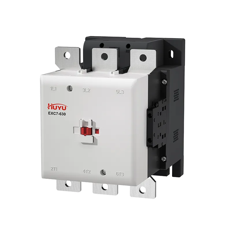
EXC7 AC Contactor
One Contactor Family from 9A to 800A — Motor, HVAC & Power Switching
The EXC7 AC contactor family spans standard contactors from 9A to 110A and high-current frames from 120A to 800A, all in 3P with a 690V insulation class (1000V on large frames). Standard models feature wide-voltage tolerance and full dust protection; high-current frames use a dual-coil control circuit that cuts holding power by more than 40%, plus built-in 2NO+2NC auxiliary contacts.
Model
EXC7 Series — AC Contactor & High-Current AC ContactorEXC7-09 ~ EXC7-110 · EXC7-120 ~ EXC7-800 (frames 120/160/185/225/265/330/400/500/630/800)
IEC 60947-4-1 · CE approved · 690V / 1000V insulation · dual-coil large frames
Product Details
- One contactor family from 9A to 110A (standard) and 120A to 800A (high-current frames), all 3P.
- Ui 690V (standard) / 1000V (high-current); switches motors from 4kW up to 450kW at 400V.
- High-current frames use a dual-coil circuit that cuts holding power by over 40% and include 2NO+2NC auxiliary contacts as standard.
- Full accessory system — auxiliary blocks, pneumatic delay heads, surge suppressors, interlocks, dust covers; IEC 60947-4-1; CE.
Product Information
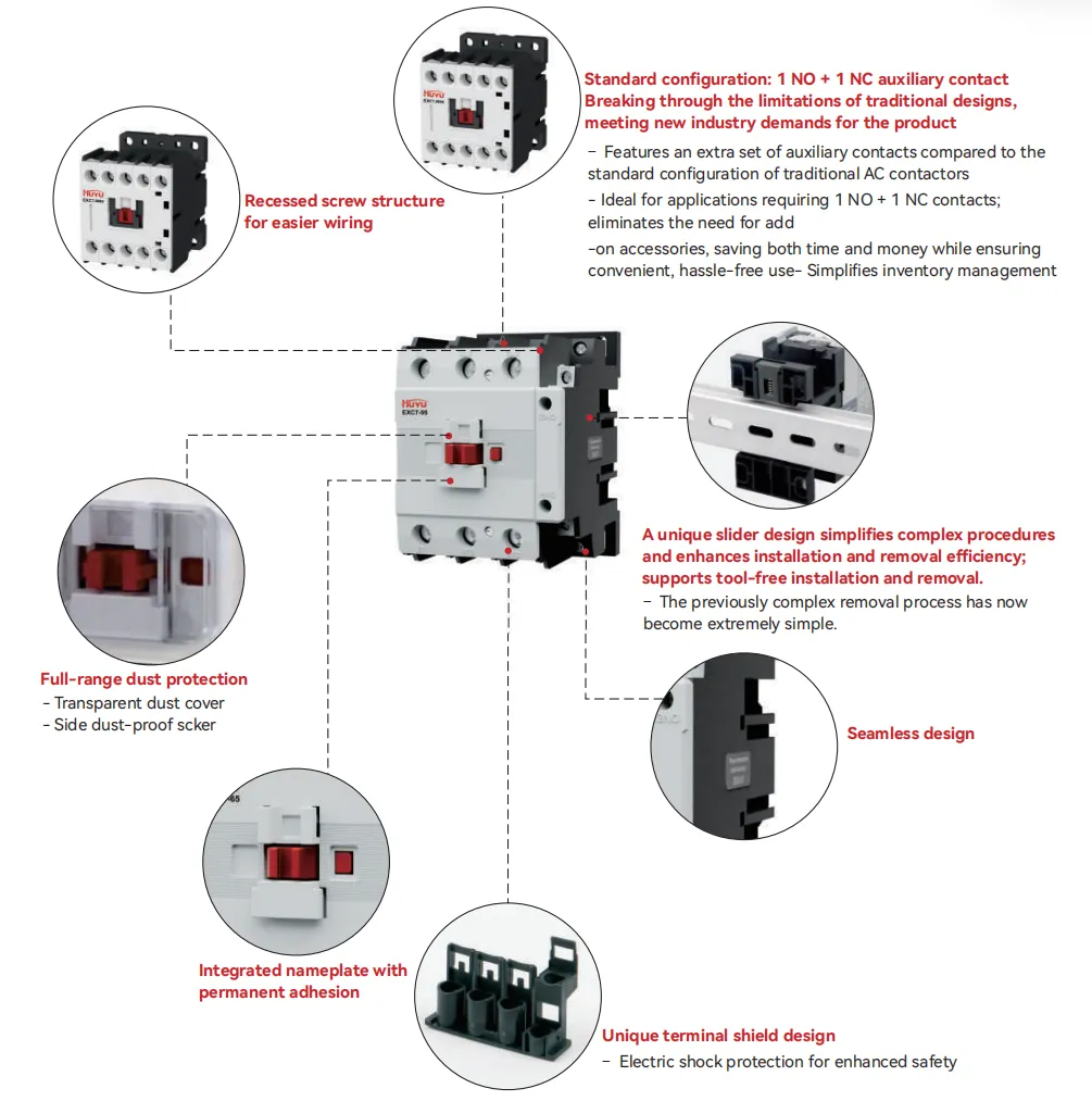
Three Key Features
- More auxiliaƔ contacts come as standard, meeting diverse application requirements
- Suitable for wider voltage Əuctuations, ensuring stable operation of the equipment
- Superior environmental adaptability, enabling reliable operation even in extreme conditions
Product Structural Analysis Diagram
Product Overview
The all-new EXC7 series AC contactors feature a novel design and a compact structure.This series is primarily used for the frequent starting and control of AC motors and for remote circuit switching; it can also be combined with a suitable thermal overload relay to form an electromagnetic staƑer.
Compliant with standards: IEC60947-1, IEC60947-4-1.
Main Technical Parameters
- Rated workingcurrent:9-95A;
- Rated workingvoltage:220Vto 69OV;
- Rated insulation voltage: 690V;
- Polarities:3P
- Installation method: rail and screw
Working Conditions and Installation Conditions
| Category | Working conditions and installation conditions |
| Installation category | Ⅲ |
| Pollution degree | 3 |
| Certification mark | CE |
| Enclosure protection class | CJX2s-09~38:IP20(excluding terminals) CJX2s-40~95:IP10;CJX2s-110:IP00 |
| Ambient air temperature | Extreme operating temperature:-35℃ to+70℃; Normal operating temperature:-5℃ to +40℃;Average temperature over a 24-hour period:not exceeding+35℃.For use outside the normal operating temperature range, please refer to the “Instructions for Use in Non-standard Environments.” |
| Altitude | Not exceeding 2000m |
| Ambient air temperature | At a maximum temperature of+70℃,relative humidity shall not exceed 50%;
higher relative humidity is permissible at lower temperatures, e.g.,up to 90%at+20℃. Special measures should be taken regarding occasional condensation caused by temperature fluctuations. |
| Installation conditions | Inclination of the mounting surface relative to the vertical plane:not exceeding±5° |
| Shock and vibration | The product should be installed and used in locations free from significant swaying,shock,and vibration. |
Instructions for Use in Extreme Temperature Environments
- The GB/T 14048.1 standard speciƍes the normal operating ambient temperature range for the product; performance remains unaffected when the product is used within this range.
- When the operating ambient temperature exceeds +40°C, the permissible temperature rise limit must be adjusted downward. In such cases, the rated operating current must be reduced, and the number of contactors installed in standard assemblies must be limited; failure to do so may result in product damage, reduced seƒice life, compromised operational reliability, and an impact on the product’s operating range.
- When the operating ambient temperature falls below -5°C, consideration must be given to the fact that greases used for insulation and lubrication may solidify at low temperatures, potentially causing product malfunction. Therefore, manufacturers and users should consult regarding design or application requirements.
- The table below lists the derating factors for rated operating current when the rated operating voltage remains constant and the operating ambient temperature exceeds 55°C.
| Ambient temperature(℃) | 55 | 60 | 65 | 70 |
| Correction Factor | 1 | 0.93 | 0.875 | 0.75 |
- +55°C to +70°C: The pick-up voltage range for the AC contactor is (90%–110%)Us. The (70%–120%)Us range represents test results obtained under cold-state conditions at an ambient temperature of 20°C.
- The following table lists the correction factors for rated impulse withstand voltage and rated operating current when the rated operating voltage remains unchanged and the altitude exceeds 2000 m:
| Altitude(m) | 2000 | 3000 | 4000 | 5000 |
| Correction Factor for Rated Impulse Withstand Voltage | 1 | 0.88 | 0.78 | 0.7 |
| Correction Factor for Rated Working Current | 1 | 0.92 | 0.9 | 0.85 |
Features and Performance
| Main Technical Parameters | ||||||||||||||
| Model(EXC7) | -9 | -12 | -18 | -25 | -32 | -38 | -40 | -50 | -65 | -80 | -95 | -110 | ||
| Main circuit characteristics | ||||||||||||||
| Polar number | 3P | |||||||||||||
| Rated insulation voltage(Ui) | V | 690 | ||||||||||||
| Rated operating voltage(Ue) | V | 380/400,660/690 | ||||||||||||
| Agreed heating current(Ith),AC-1 rated operating current | 20 | 25 | 32 | 40 | 50 | 50 | 60 | 80 | 80 | 100 | 125 | 140 | ||
| Rated working
current (le) |
AC-3,380/400V | A | 9 | 12 | 18 | 25 | 32 | 38 | 40 | 50 | 65 | 80 | 95 | 110 |
| AC-3,660/690V | A | 6.6 | 8.9 | 12 | 18 | 22 | 22 | 34 | 39 | 42 | 49 | 49 | 86 | |
| AC-4,380/400V | A | 3.5 | 5 | 7.7 | 8.5 | 12 | 14 | 18.5 | 24 | 28 | 37 | 44 | 51 | |
| AC-4,660/690V | A | 1.5 | 2 | 3.8 | 4.4 | 7.5 | 8.9 | 9 | 12 | 14 | 17.3 | 21.3 | 25 | |
| Rated working power(Pe) |
AC-3,380/400V | kW | 4 | 5.5 | 7.5 | 11 | 15 | 18.5 | 18.5 | 22 | 30 | 37 | 45 | 55 |
| AC-3,660/690V | kW | 5.5 | 7.5 | 10 | 15 | 18.5 | 18.5 | 30 | 37 | 37 | 45 | 45 | 80 | |
| AC-4,380/400V | kW | 1.5 | 2.2 | 3.3 | 4 | 5.4 | 5.5 | 7.5 | 11 | 15 | 18.5 | 22 | 25.5 | |
| AC-4,660/690V | kW | 1.1 | 1.5 | 3 | 3.7 | 5.5 | 6 | 7.5 | 10 | 11 | 15 | 18.5 | 21.7 | |
| Mechanical life | 10,000 times | 1200 | 1000 | 900 | 650 | |||||||||
| Electrical life | AC-3 | 10,000 times | 110 | 90 | 65 | |||||||||
| AC-4 | 10,000 times | 22 | 17 | 11 | ||||||||||
| Operating
frequency |
AC-3 | Times per hour | 1200 | 600 | ||||||||||
| AC-4 | Times per hour | 300 | 180 | |||||||||||
| The wiring capability of the main circuit terminals | ||||||||||||||
| Flexible wire
With terminal blocks |
1 wire | mm² | 1….4 | 1.…6 | 2.5…25 | 4…50 | 10…150 | |||||||
| 2 wires | mm² | 1.….2.5 | 1..4 | 2.5.…10 | 4..16 | 10…75 | ||||||||
| Hard wire
No terminal blocks |
1 wire | mm² | 1….4 | 1.5.….6 | 1.5…10 | 2.5.…25 | 4…50 | 10…150 | ||||||
| 2 wires | mm² | 1.…4 | 1.5.…6 | 2.5.…10 | 4.….25 | 10…75 | ||||||||
| Fastening torque | N.m | 1.2 | 1.8 | 6 | 9 | 10 | ||||||||
| Coil | ||||||||||||||
| Rated control circuit voltage(Us) |
50Hz | V | 24、36、48、110、127、220/230、240、380/400、415、440 | |||||||||||
| 50/60Hz | V | 24、36、48、110、127、220/230、240、380/400、415、440 | ||||||||||||
| Allowable control circuit voltage(Us) |
Operation | V | 70%~120% | |||||||||||
| Release | V | 20%~65% | ||||||||||||
| Coil power
consumption |
Pull-in | VA | 60 | 70 | 200 | 200 | ||||||||
| Holding | VA | ≤9.0 | ≤14 | ≤25 | ≤25 | |||||||||
| Auxiliary contact | ||||||||||||||
| Contact specification | A | 1NO/1NC | ||||||||||||
| Agreed heating current(Ith) | A | 10 | ||||||||||||
| Rated operating | AC | V | 380 | |||||||||||
| voltage(Ue) | SD | V | 220 | |||||||||||
| Rated control | AC-15 | VA | 360 | |||||||||||
| capacity | DC-13 | W | 33 | |||||||||||
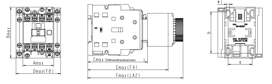
Shape and Installation Dimensions
CJX2s–09~38
CJX2s–40~95
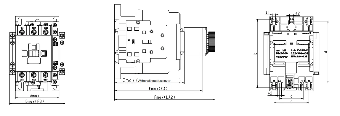
CJX2s–110
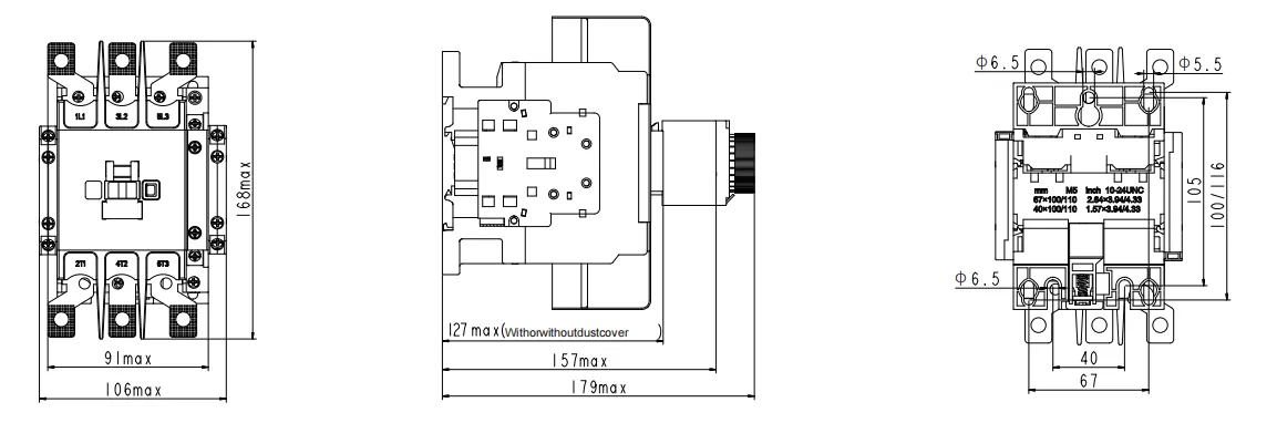
| Model | Amax | Bmax | Cmax | Dmax | Emax | a | b | C | d | Φ 1 | Φ2 |
| EXC7-09,12,18 | 74.5 | 45.5 | 89 | 68 | 119 | 34 | 50/60 | – | 4.5 | 一 | |
| EXC7-25,32,38 | 83 | 56.5 | 100 | 79 | 130 | 40 | 50/72 | 一 | 一 | 4.5 | – |
| EXC7-40,50,65 | 127.5 | 74.5 | 120 | 96 | 150 | 59 | 116 | 40 | 105 | 5.5 | 6.5 |
| EXC7-80,95 | 127.5 | 85.5 | 127 | 107 | 157 | 67 | 116 | 40 | 105 | 5.5 | 6.5 |
CJX2s-09~95+JR28s-25~93
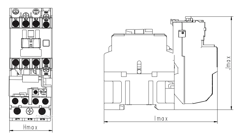
| Model | Hmax | Imax | Jmax |
| EXC7-09~18 | 47 | 122 | 100 |
| EXC7-25 | 58 | 130 | 107 |
| EXC7-32~38 | 58 | 143 | 96 |
| EXC7-40~65 | 75 | 174 | 125 |
| EXC7-80~95 | 86 | 180 | 128 |
CJX2s-09N~95N
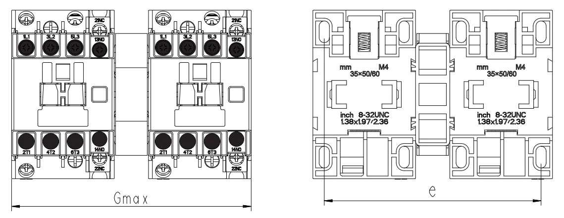
| Model | Gmax | e |
| EXC7-09~18 | 107 | 95 |
| EXC7-25~38 | 130 | 110.5/111.5 |
| EXC7-40~65 | 164 | 148 |
| EXC7-80~95 | 186 | 166.5 |
EXC7 High-current AC Contactor
Three Key Features
- Dual-coil control circuit, compliant with the trend of energy conseƒation and consumption reduction
- Adaptable to wider voltage Əuctuations, ensuring stable equipment operation
- Superior environmental adaptability, reliable operation even in extreme conditions
Product Structural Analysis Diagram
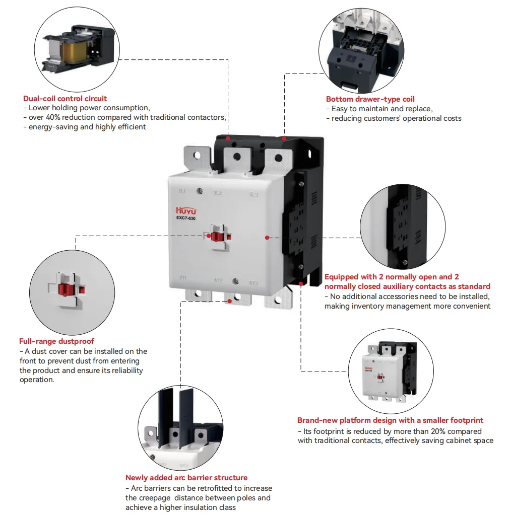
Product Overview
The new EXC7-120~80oA series AC contactors feature an innovative appearance and a compact structure. They are mainly used for frequent staƑing and control of AC motors, remote switching on and oƆ of circuits, and can be combined with appropriate thermal overload relays to form electromagnetic starters
Complies with standards: GB/T 14048.1/lEC 60947-1,GB/T 14048.4/lEC 60947-4-1
Main Technical Parameters
- Rated working current: 120-800A;
- Rated working voltage: 220V to 690V;
- Rated insulation voltage: 1000V;
- Polarities: 3P
- Installation method: rail and screw
Working Conditions and Installation Conditions
| Category | Working conditions and installation conditions |
| Installation category | Ⅲ |
| Pollution degree | 3 |
| Enclosure protection class | IP00 |
| Ambient air temperature | The maximum operating temperature is-35℃ to +70℃,and thenormal operating temperature is
-5℃ to +40℃ The average value within 24 hours does not exceed +35℃. If used outside the normal operating temperature range,for details,please refer to the “Instructions for Use in Abnormal Environments” |
| Altitude | No more than 2000m |
| Ambient air temperature | When the maximum temperature is+70℃,the relative humidity of the air shall not exceed 50%.
Higher relative humidity is allowed at lower temperatures For example,it reaches 90%at+20℃. Special measures should be taken for condensation that occasionally occurs due to changes in humidity |
| Installation conditions | The inclination between the installation surface and the vertical surface shall notexceed+5°. |
| Shock and vibration | The product should be installed and used in a place free from significant shaking,shock and vibration |
Instructions for Use in Abnormal Temperature Environments
- The GB/T 14048.1 standard speciƍes the normal operating ambient temperature for the product.When used within the normal operating ambient temperature range, the product’s peƐormance is not signiƍcantly affected.
- When the operating ambient temperature exceeds +40°C, it is necessaƔ to consider derating the permissible temperature rise limit. In such cases, the rated operating current must be reduced, and the number of contactors installed in standard assemblies must be decreased. Failure to do so may result in product damage, reduced seƒice life, diminished operational reliability, and an impact on the product’s operating range.
- When the operating ambient temperature falls below -5°C, consideration must be given to the fact that greases used for insulation and lubrication may solidify at low temperatures, potentially causing product failure. Therefore, the manufacturer and the user should consult regarding design or usage requirements.
- The table below lists the rated operating current derating factors for instances where the rated operating voltage remains constant but the operating ambient temperature exceeds 55°C.
| Ambient temperature(℃) | 55 | 60 | 65 | 70 |
| Correction Factor | 1 | 0.93 | 0.875 | 0.75 |
- +55°C~+70°C: The pull-in voltage range of the AC contactoris(90%~110%)Us.The range of(70% ~120%)Us is the testresult obtained under the condition of cold state atnormaltemperature of 20°C
- The following table provides correction factors for the rated impulse withstand voltage and rated workingcurrent when the altitude exceeds 20oom with the rated working voltage remains unchanged:
| Altitude(m) | 2000 | 3000 | 4000 | 5000 |
| Correction Factor for Rated Impulse Withstand Voltage | 1 | 0.88 | 0.78 | 0.7 |
| Correction Factor for Rated Working Current | 1 | 0.92 | 0.9 | 0.85 |
Features and Performance
| Main Technical Parameters | ||||||||||||
| Frame Size | 120 | 160 | 185 | 225 | 265 | 330 | 400 | 500 | 630 | 800 | ||
| Main circuit characteristics | ||||||||||||
| Polar number | 3P | |||||||||||
| Rated insulation voltage(Ui) | V | 1000 | ||||||||||
| Rated operating voltage(Ue) | V | 380/400,660/690 | ||||||||||
| Agreed heating current(Ith),AC-1 rated operating current | 200 | 200 | 275 | 275 | 315 | 380 | 450 | 630 | 700 | 900 | ||
| Rated working current(le) |
AC-3,380/400V | A | 120 | 160 | 185 | 225 | 265 | 330 | 400 | 500 | 630 | 800 |
| AC-3,660/690V | A | 86 | 107 | 107 | 118 | 170 | 235 | 303 | 353 | 400 | 470 | |
| Rated working power(Pe) |
AC-4,380/400V | kW | 55 | 75 | 90 | 110 | 132 | 160 | 200 | 250 | 335 | 450 |
| AC-4,660/690V | kW | 80 | 100 | 100 | 110 | 160 | 200 | 300 | 335 | 350 | 375 | |
| Mechanical life | 10,000 times | 600 | ||||||||||
| Electrical life | AC-3 | 10,000 times | 120 | 80 | ||||||||
| Operating frequency | AC-3 | 10,000 times | 800 | 600 | ||||||||
| The wiring capability of the main circuit terminals | ||||||||||||
| Flexible wire
With terminal blocks |
1 wire | mm² | 10.…95 | 10…150 | / | |||||||
| 2 wires | mm² | 10.…95 | 10…75 | / | ||||||||
| Hard wire
No terminal blocks |
1 wire | mm² | 10.…95 | 10.…150 | 50…240 | |||||||
| 2 wires | mm² | 10.…95 | 10.….75 | 50.…240 | ||||||||
| Fastening torque | N.m | 10 | 14 | |||||||||
| Coil | ||||||||||||
| Rated control circuit voltage(Us) |
50Hz | V | 110V、127V、220/230V、380/400V | |||||||||
| 50/60Hz | V | 75%~120% | ||||||||||
| Allowable control circuit voltage(Us) |
Operation | V | 20%70% | |||||||||
| Release | V | |||||||||||
| Coil power consumption |
Pull-in | VA | ≤300 | ≤500 | ≤600 | ≤800 | ||||||
| Holding | VA | ≤30 | ≤11 | |||||||||
| Auxiliary contact | ||||||||||||
| Contact specification | A | / | 2NO/2NC | |||||||||
| Agreed heating current(Ith) | A | 10 | ||||||||||
| Rated operating | AC | V | 380 | |||||||||
| voltage(Ue) | SD | V | 220 | |||||||||
| Rated control | AC-15 | VA | 360 | |||||||||
| capacity | DC-13 | W | 33 | |||||||||
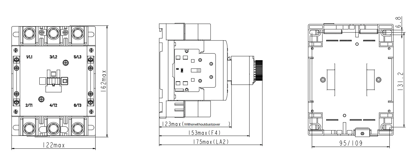
Shape and Installation Dimensions
CJX2s-120–160
CJX2s-185-800
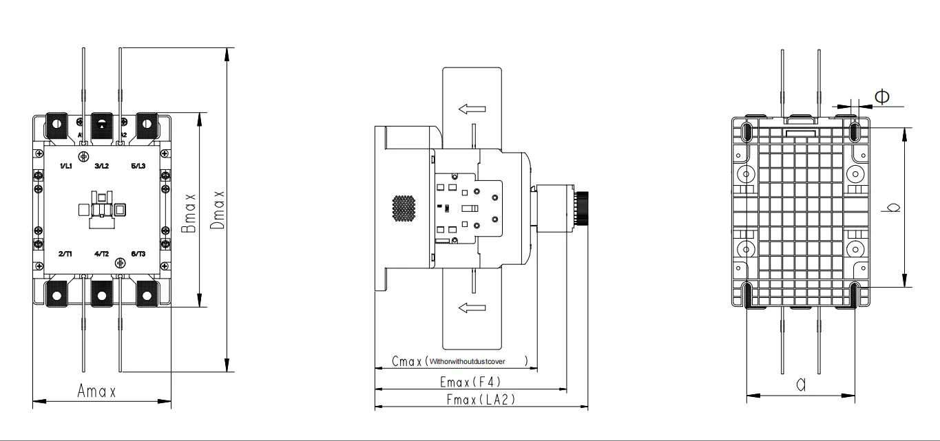
| Model | Amax | Bmax | Cmax | Dmax | Emax | Fmax | a | b | Φ |
| EXC7-185-265 | 124 | 174 | 167 | 290 | 197 | 219 | 96 | 113.5/141.5 | 7 |
| EXC7-330-500 | 156 | 212 | 210 | 318 | 239 | 261 | 120 | 180/186 | 9 |
| EXC7-630-800 | 171 | 231 | 236 | 333 | 333 | 288 | 133 | 180/186 | 9 |
EXC7 Accessory Selection Guide
Product Installation Diagram
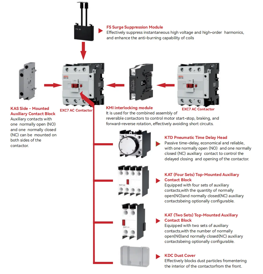
Surge Suppression Module Technical Parameters
| Product Appearance | Product Model | Delay Range(s) | Delay Type | Applicable Contactor Model |
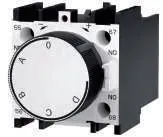 |
KTD-C1 | 0.1-3 | On-delay | EXC7-09~630 |
| KTD-C2 | 0.1-30 | |||
| KTD-C3 | 10-180 | |||
| KTD-D1 | 0.1-3 | Off-delay | ||
| KTD-D2 | 0.1-30 | |||
| KTD-D3 | 10-180 |
Technical Parameters of Auxiliary Contact Block
| Product Appearance | Product Model | NO(Normally Open) | NC(Normally Closed) | Applicable Contactor Model | |
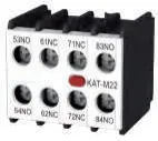 |
KAT-M20 | 2 | 0 | EXC7-M06~M16 | |
| KAT-M11 | 1 | 1 | |||
| KAT-M02 | 0 | 2 | |||
| KAT-M40 | 4 | 0 | |||
| KAT-M31 | 3 | 1 | |||
| KAT-M22 | 2 | 2 | |||
| KAT-M13 | 1 | 3 | |||
| KAT-M04 | 0 | 4 | |||
 |
KAT-20 | 2 | 0 | EXC7-09~630 | |
| KAT-11 | 1 | 1 | |||
| KAT-02 | 0 | 2 | |||
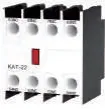 |
KAT-40 | 4 | 0 | ||
| KAT-31 | 3 | 1 | |||
| KAT-22 | 2 | 2 | |||
| KAT-13 | 1 | 3 | |||
| KAT-04 | 0 | 4 | |||
 |
KAS-20 | 2 | 2 | ||
| KAS-11 | 1 | 1 | |||
| KAS-02 | 0 | 2 | |||
Mechanical Linkage Matching
| Product Appearance | Product Model | Applicable Contactor Model |
 |
KMI Mechanical Chain Store | EXC7-09~38 |
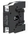 |
KMI Electrical Chain Store | EXC7-09~95 |
Dust Cover Matching
| Product Appearance | Product Model | Applicable Contactor Model |
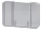 |
KDC-1 | EXC7-09~38 |
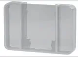 |
KDC-2 | EXC7-40~95 |
Surge Suppression Module Technical Parameters
| Product Appearance | Product Model | Matched Fuse Rang(A) | Applicable Contactor Model |
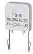 |
FS-M | AC/DC 24~48V
AC/DC 100~250V AC/DC 380~440V |
EXC7-M06~M16 |
 |
FS-18 | EXC7-09~18 | |
| FS-32 | EXC7-25~32 | ||
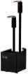 |
FS-65 | EXC7-40~65 | |
| FS-95 | EXC7-80~95 |
Technical Parameters of Thermal Overload Relay
| Product Appearance | Rated Current(A) | Matched Fuse Rang(A) | Applicable Contactor Model | ||
| aM | gG | ||||
JR28s-25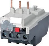 |
0.1~0.16 | 0.25 | 2 | EXC7-09
EXC7-12 EXC7-18 EXC7-25 |
|
| 0.16~0.25 | 0.5 | 2 | |||
| 0.25~0.4 | 1 | 2 | |||
| 0.4~0.63 | 1 | 2 | |||
| 0.63~1 | 2 | 4 | |||
| 1~1.6 | 2 | 4 | |||
| 1.25~2 | 4 | 6 | |||
| 1.6~2.5 | 4 | 6 | |||
| 2.5~4 | 6 | 10 | |||
| 4~6 | 8 | 16 | |||
| 5.5~8 | 12 | 20 | |||
| 7~10 | 12 | 20 | |||
| 9~13 | 16 | 25 | |||
| 12~18 | 20 | 35 | |||
| 17~25 | 25 | 50 | |||
JR28s-36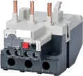 |
23~32 | 40 | 63 | EXC7-32
EXC7-38 |
|
| 28~36 | 40 | 80 | |||
JR28s-93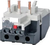 |
23~32 | 40 | 63 | EXC7-40
EXC7-50 EXC7-65 EXC7-80 EXC7-95 |
|
| 30~40 | 40 | 100 | |||
| 37~50 | 63 | 100 | |||
| 48~65 | 63 | 100 | |||
| 55~70 | 80 | 125 | |||
| 63~80 | 80 | 125 | |||
| 80~93 | 100 | 160 | |||
How We Support Your Business

OEM / ODM
Custom coils, accessory kits and branding on the full EXC7 platform, with IEC type-test documentation for switchgear certification.
Custom coils · Accessory kits · Type tests

Wholesale
Factory-direct pricing and mixed-frame containers for distributors covering the whole contactor category from 9A to 800A.
Factory pricing · Mixed frames · Global shipping

Distributor Support
Application engineering, cross-reference lists and priority production for partners serving motor control and switchgear markets.
Application support · Cross references · Priority lead times
Ready to Standardise on the EXC7 Family?
OEM/ODM, wholesale pricing and distributor support — one enquiry gets you a factory-direct quotation across the EXC7 range from 9A to 800A, with the coils and accessories your panel needs.
Frequently Asked Questions
What is the difference between the EXC7 standard and high-current series?
The standard EXC7 series covers 9A to 110A (AC-3 at 400V) with a 690V insulation class and is used for motors up to 55kW. The high-current series covers frames from 120A to 800A with 1000V insulation, a dual-coil energy-saving control circuit and standard 2NO+2NC auxiliary contacts — for large motors, incoming feeders and power switching up to 450kW.
What does AC-3 vs AC-4 mean for contactor sizing?
AC-3 is normal motor duty: starting a motor and cutting it while running. AC-4 is severe duty: inching and plugging, where the contactor opens and closes while the motor is starting or reversing, drawing up to six times rated current. A contactor sized for AC-3 must be derated for AC-4 use — the EXC7 technical tables list both current columns so you can size accordingly.
How does the dual-coil circuit save energy?
Conventional contactors hold their armature with a coil sized for the high pull-in current, wasting energy continuously. The EXC7 high-current frames energise a high-power coil only for the pull-in moment, then switch to a low-power holding coil. Holding consumption falls by over 40%, reducing heat and power cost in panels where contactors stay energised for hours.
Can the EXC7 be combined with thermal overload relays?
Yes. The EXC7 mates directly with JR28s thermal overload relays (JR28s-25 for 09-25, JR28s-36 for 32-38, JR28s-93 for 40-95), forming an electromagnetic starter with overload and phase-loss protection. For the EXQ7 assembled starter or motor-control applications, contact our sales team for matched sets.
Which auxiliary and accessory options are available?
The EXC7 family is supported by top-mounted auxiliary contact blocks (KAT, NO/NC combinations up to 4 contacts), side-mounted blocks (KAS), pneumatic time-delay heads (KTD), dust covers (KDC), surge suppression modules (FS) and mechanical/electrical interlocks (KMI) for reversing contactor pairs — all listed in the EXC7 accessory selection guide.