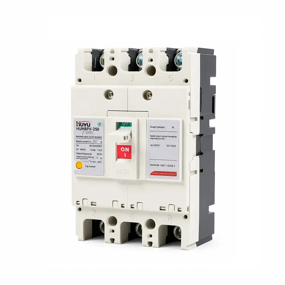
Disjuntor Moldado Fotovoltaico HUM8PV
A série HUM8PV é um disjuntor em caixa moldada fotovoltaico classificado para 16A–690A em DC 1000V. Fornece proteção contra sobrecarga com retardo de tempo longo e proteção instantânea contra curto-circuito. Disponível em 3P e 4P com múltiplos acessórios (liberação por derivação, contatos auxiliares/alarmes, mecanismo de motor). Conforme IEC 60947-2. Para sistemas solares fotovoltaicos, caixas combinadoras e distribuição DC.
Padrão: IEC 60947-2
Corrente Nominal: 16A – 690A (estrutura 125/250/400/630)
Tensão Nominal: DC 1000V
Polos: 3P, 4P
Capacidade de interrupção (Icu/Ics): Até 65kA / 50kA (DC750V)
Aplicações: Sistemas solares fotovoltaicos, caixas combinadoras, distribuição DC, proteção de inversores
Informações do Produto
Aplicação
O disjuntor em caixa moldada fotovoltaico HUM8PV (doravante referido como disjuntor) é aplicado ao circuito DC com tensão nominal até DC1000 V e corrente nominal de 16A a 690A. Com funções de proteção contra sobrecarga com retardo de tempo longo e proteção instantânea contra curto-circuito, o produto pode distribuir energia elétrica e proteger a linha e o equipamento contra danos causados por sobrecarga, curto-circuito e outras falhas. Este produto está em conformidade com a norma IEC60947-2.
Condições normais de operação
Temperatura ambiente: -25°C~+70°C; temperatura média em 24h: ≤+35°C
Altitude: ≤ 2000m
Umidade: A umidade relativa do ar na temperatura máxima de +40°C não pode ultrapassar 50%; sob a temperatura mínima com umidade relativa mais alta, a temperatura média do mês mais úmido não pode ultrapassar +25°C, e a umidade relativa média não pode exceder 90%;
Grau de poluição: classe 3
Montado em locais sem risco de explosão, sem gases que possam ser corrosivos para metais ou gases que possam danificar o isolamento, e com pouca poeira condutiva
Categoria de montagem: III
Modelo e significado
Modelo e significado
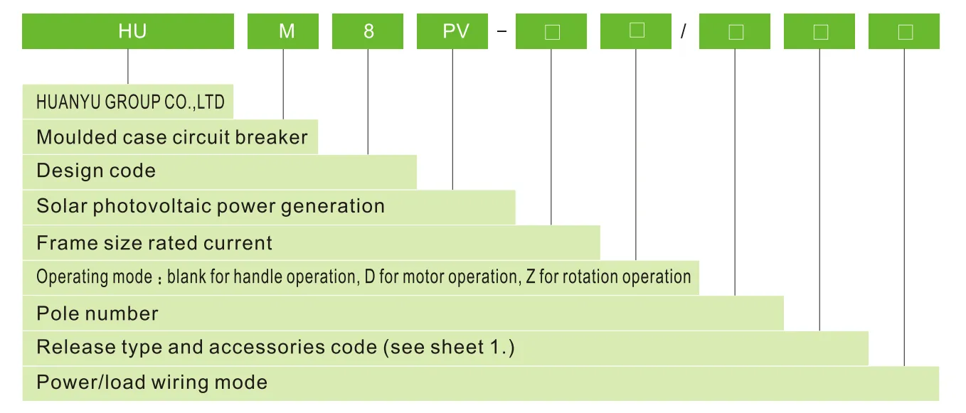
Tipo de liberação e código de acessórios
| Acessórios nome |
Não acessórios |
Contato de alarme contato |
Liberação por derivação liberação |
Auxiliar contato |
Liberação por derivação e auxiliar contato |
Dois grupos de contatos auxiliares contatos |
Liberação por derivação e contato de alarme contato |
Auxiliar contato e contato de alarme |
Liberação por derivação, contato auxiliar e contato de alarme |
Dois grupos de contatos auxiliares, contatos, contato de alarme |
| Tipo de liberação por sobrecorrente | Código | |||||||||
| Liberação instantânea | 200 | 208 | 210 | 220 | 240 | 260 | 218 | 228 | 248 | 268 |
| Liberação dupla | 300 | 308 | 310 | 320 | 340 | 360 | 318 | 328 | 348 | 368 |
| Nota: Conforme o modo de fiação de energia/carga, tipo E, F para 3P; tipo G, H, I para 4P | ||||||||||
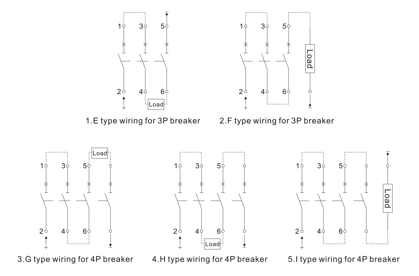
Para sistemas de energia com os modos de fiação acima, consulte a folha 2.
| Para sistema de isolamento à terra | Sistema de aterramento negativo | Sistema de aterramento do ponto neutro | |
| DC 500V | E | E, F | – |
| DC750V | E、H | F、G、I | H |
| DC1000V | H | 1 | H |
Principais parâmetros técnicos
| Corrente nominal do tamanho da estrutura | 125 | 250 | 400 | 630 | |||||
| Corrente nominal In(A) | €�20、25、32、40、50、63、80、100、125 | €�125、160、180、200、225、250 | €�250、315、350、400 | €�500、630 | |||||
| Número de polos | 3 | 4 | 3 | 4 | 3 | 4 | 3 | 4 | |
| Tensão de isolamento nominal Ui(V) | 1000 | ||||||||
| Tensão nominal de impulso suportada Uimp(V) | 8000 | ||||||||
| Tensão nominal de trabalho Ue(V) | DC 500 DC750 |
DC750 DC 1000 |
DC 500 DC750 |
DC750 DC 1000 |
DC 500 DC750 |
DC750 DC 1000 |
DC 500 DC750 |
DC750 DC 1000 |
|
| Categoria de uso | A | ||||||||
| Limite/serviço nominal curto-circuito capacidade de interrupção Icu/lcs(kA) |
DC500 | 15/15 | 65/65 | 65/65 | 65/65 | ||||
| DC750 | 5/5 | 15/15 | 40/20 | 50/50 | 40/20 | 50/50 | 40/20 | 50/50 | |
| DC1000 | 5/5 | 40/20 | 40/20 | 40/20 | |||||
| Distância de arco (mm) | ≤50 | ≤50 | ≤100 | ≤100 | |||||
| Operação desempenho (vezes) |
Energizado | 5000 | 5000 | 1000 | 1000 | ||||
| Não energizado | 10000 | 10000 | 5000 | 5000 | |||||
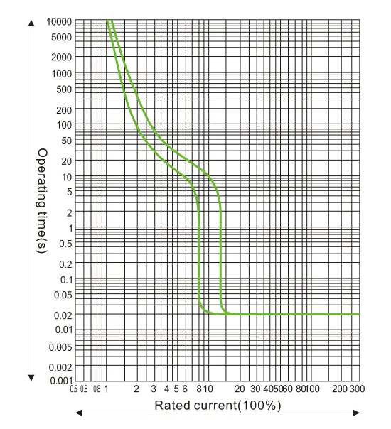
Curva das características de proteção
Curva das características de proteção de temperatura e corrente HUM8PV-125
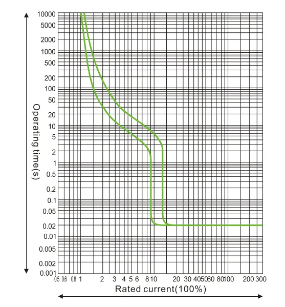
Curva das características de proteção de temperatura e corrente HUM8PV-250
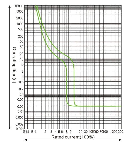
Curva das características de proteção de temperatura e corrente HUM8PV-400
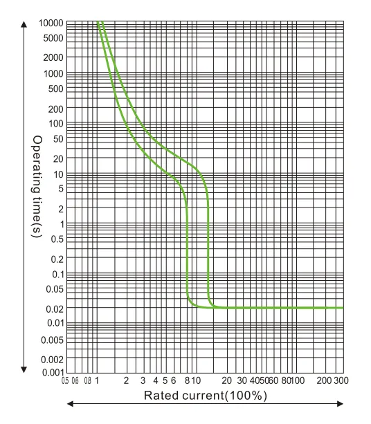
Curva das características de proteção de temperatura e corrente HUM8PV-690
Coeficiente de redução da capacidade térmica em diferentes temperaturas.
| 10℃ | 20℃ | 30℃ | 40℃ | 50℃ | 60℃ | 70℃ | |
| HUM8PV-125 | 15In | 11In | 15In | 1In | 93In | 85In | 8In |
| HUM8PV-250 | 15In | 11In | 15In | 1In | 93In | 85In | 79In |
| HUM8PV-400 | 16ln | 11In | 15In | 1In | 94In | 86ln | 81In |
| HUM8PV-630 | 17In | 11In | 15In | 1In | 9In | 8In | 7In |
O coeficiente de redução de capacidade em alta altitude: quando a altitude excede 2000m, o disjuntor deve ser ajustado conforme a folha 4
| Altitude (m) | 2000 | 3000 | 4000 | 5000 |
| Tensão suportada em frequência de potência | 3000 | 2500 | 2000 | 1800 |
| Coeficiente de ajuste da corrente de trabalho | 1 | 0.94 | 0.88 | 0.83 |
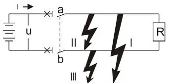
Aplicação em sistema DC: os seguintes aspectos devem ser considerados antes de escolher o disjuntor em sistema DC.
a. tensão nominal de operação, considerando o número de polos em cascata
b. corrente nominal, considerando a potência da carga
c. capacidade de interrupção, considerando a corrente máxima de curto-circuito no local de instalação
d. modo do sistema de aterramento, ver folha 5
| Tipo de sistema | Sistema de aterramento | Sistema sem aterramento | ||
| Todos os tipos de falhas | 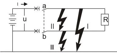 |
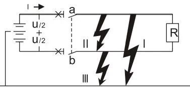 |
 |
|
| Efeito da falha | Falha I | Gera corrente máxima de curto-circuito Contato conectado ao polo positivo interrompe |
Tensão U/2 produz corrente máxima de curto-circuito Contato conectado ao polo negativo interrompe |
Sem efeito |
| Falha II | Gera corrente máxima de curto-circuito Todos os contatos em cascata interrompem |
Gera corrente máxima de curto-circuito Todos os contatos em cascata interrompem |
Gera corrente máxima de curto-circuito Todos os contatos em cascata interrompem |
|
| Falha I | Sem efeito | Igual à falha I Mas somente para contato conectado ao polo negativo |
Sem efeito | |
| A pior situação | Falha I | Falha I e Falha II | Falha II | |
| Situação de interrupção | Cascata no polo positivo e interrupção conjunta | Para cada polo, interrompe corrente máxima de curto-circuito quando U/2 | Dois polos interrompem juntos | |
Dimensões gerais e de montagem
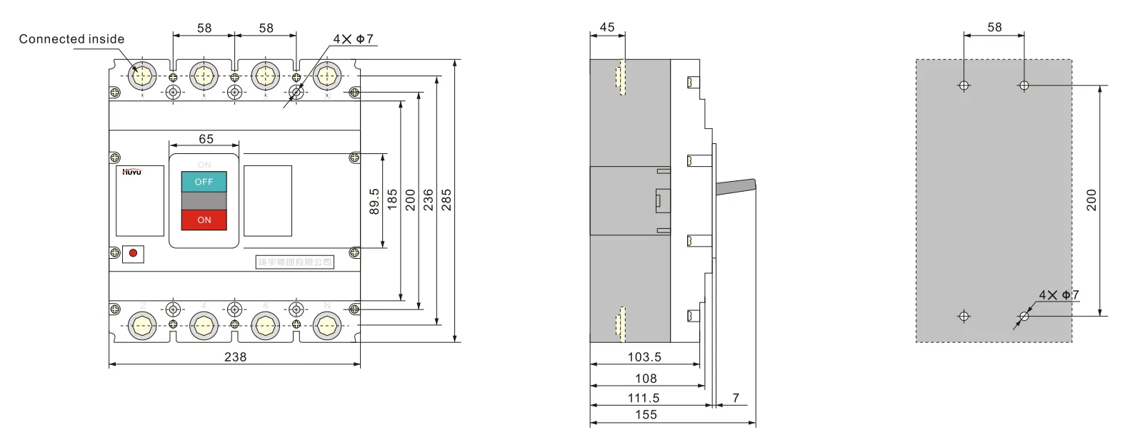
Fiação tipo E para 3P HUM8PV-125 (conexão frontal)
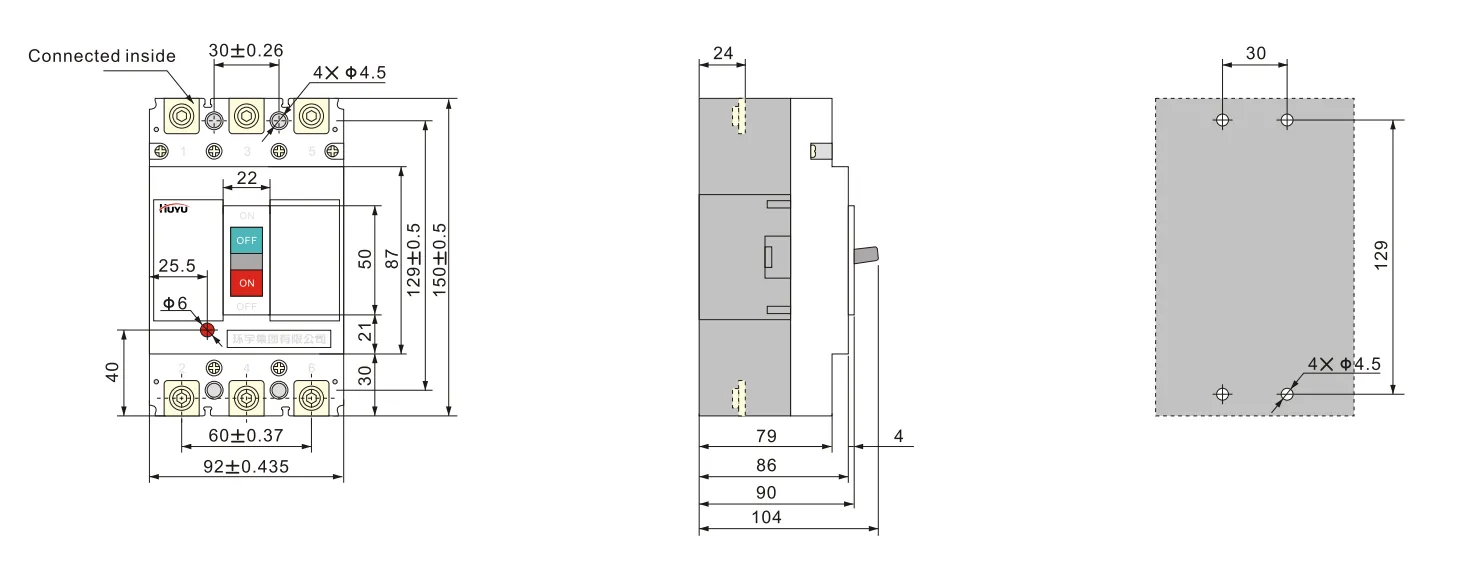
Fiação tipo H para 4P HUM8PV-125 (conexão frontal)
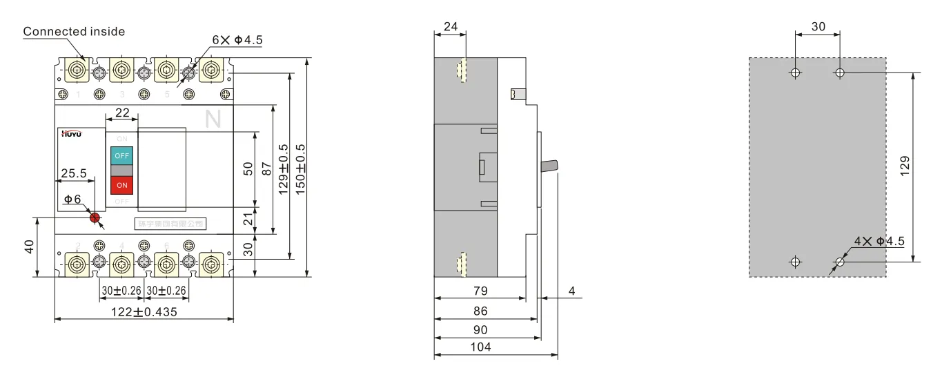
Fiação tipo E para 3P HUM8PV-250 (conexão frontal)
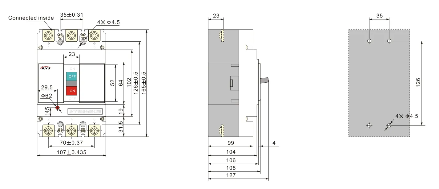
Fiação tipo H para 4P HUM8PV-250 (conexão frontal)
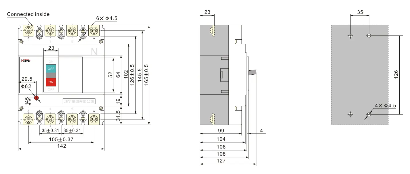
Fiação tipo E para 3P HUM8PV-400 (conexão frontal)
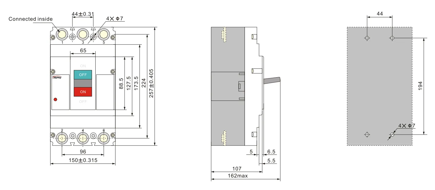
Fiação tipo H para 4P HUM8PV-400 (conexão frontal)
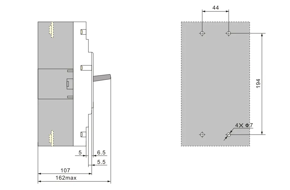
Fiação tipo E para 3PHUM8PV-630 (conexão frontal)
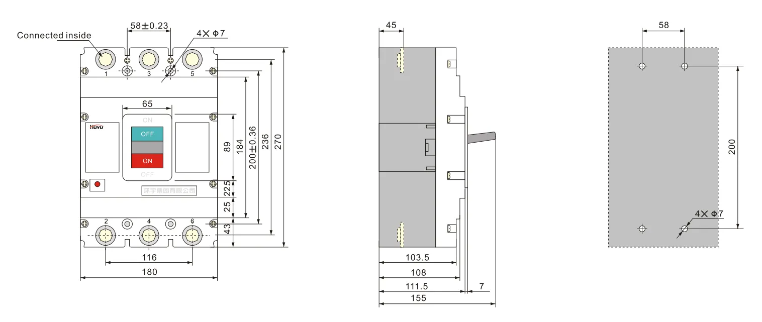
Fiação tipo H para 4P HUM8PV-630 (conexão frontal)
Acessórios
Acessórios podem ser fornecidos conforme a exigência do usuário.
Parâmetros do disparo por solenóide:
Tensão nominal Us: AC230V, 400V; DC 220-250V, 24-30V
O disjuntor pode interromper com confiabilidade em (70%-110%) Us, e o tempo de atuação é de 10ms-30ms.
Nota: ao usar disparo por solenóide DC24V-30V, o comprimento máximo do cabo de cobre deve atender aos requisitos da folha 6
| Tensão nominal de alimentação de controle Us (DC24V~30V) |
Potência de entrada | Comprimento máximo do cabo de cobre | |
| 1,5mm² | 2,5mm² | ||
| 100%Us | 50W | 150m | 250m |
| 85%Us | 50W | 100m | 160m |
Valor nominal do contato auxiliar e contato de alarme:
Corrente térmica convencional Ith=3A; corrente nominal de trabalho Ie=0,79A (AC230V); Ie=0,47A (AC400V); Ie=0,15A (DC250V)
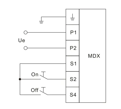
Parâmetros do mecanismo de operação do motor veja folha 7, altura total do mecanismo de operação do motor veja folha 8. A seguir está o diagrama de fiação do mecanismo de operação do motor
| Corrente nominal do tamanho da estrutura Ie (A) | Tensão nominal de trabalho Ue(V) | Corrente de partida (A) | Tempo de atuação (s) | Frequência nominal de operação (vezes/h) | Vida mecânica (vezes) |
| 125 | AC 110V~230V 50Hz DC 110V~220V |
≤0,5 | ≤0,8 | 180 | 9000 |
| 250 | |||||
| 400 | ≤2 | 120 | 5000 | ||
| 630 | 3000 |
A capacidade de potência do mecanismo de operação do motor deve ser suficiente para garantir que a tensão aplicada na corrente de partida não seja inferior a 85%Ue
| Modelo | HUM8PV-125 | HUM8PV-250 | HUM8PV-400 | HUM8PV-630 |
| Altura | 170 | 199 | 230 | 246 |
Diagrama de fiação do mecanismo de operação do motor
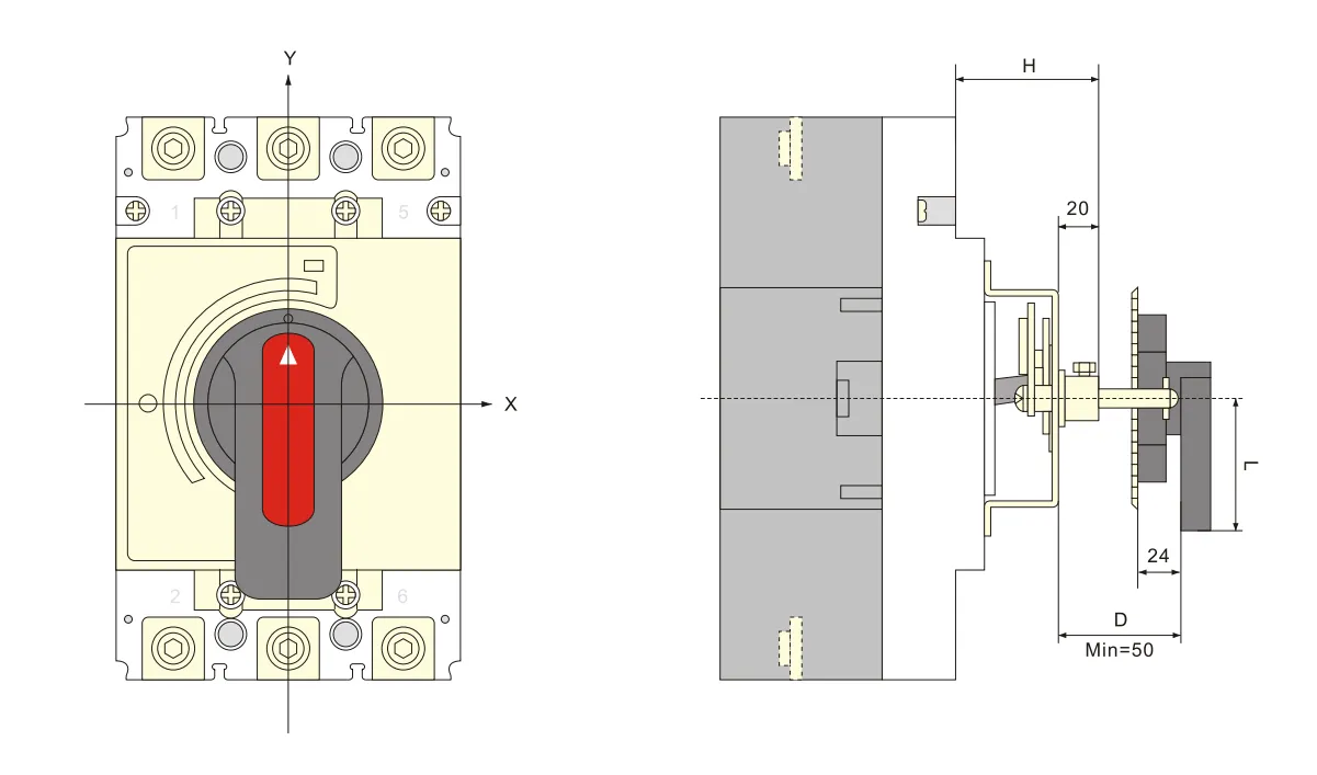
Tamanho de montagem do mecanismo de operação com alavanca giratória veja folha 9
| Modelo | HUM8PV-125 | HUM8PV-250 | HUM8PV-400 | HUM8PV-630 |
| Tamanho de montagem (H) | 54 | 54 | 76 | 83 |
Desenho geral e dos furos de montagem da alavanca tipo A (quadrada)
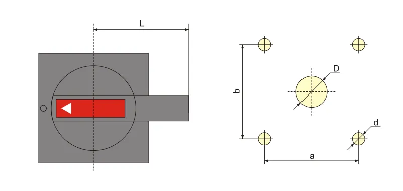
| Modelo e especificação | A1 | A2 |
| D | Médio 42 | φ 63 |
| d | Médio 4,5 | φ5.5 |
| a | 65 | 88 |
| b | 65 | 88 |
| L | 60 | 140 |
Overall and mounting hole drawing of B type(round)handle
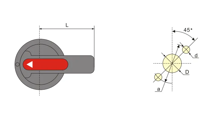
| Modelo e especificação | B1 | B2 | B3 |
| D | φ33 | φ33 | 中33 |
| d | Médio 4,5 | φ4.5 | Médio 4,5 |
| a | φ 53 | φ53 | φ53 |
| L | 65 | 125 | 95 |
Overall and mounting sizes of centralized rotating handle operation mechanism
8.Installation and maintenance
1.Matters need attention before installation:
a.Appearance shall be well and no-loaded action normal; rated value of breaker and accessories should conform to working conditions at mounting site;no obvious shock at mounting site and conform to normal working conditions
b. Insulation test should be taken before ex-factory. Use 1000VDCMo meter to do retest before installation, among poles of circuit breaker,the insulating resistance between the same pole entering and outlet terminal should be no less than 20MΩ at breaking state
2.Cross section area of conductors should exceed the size regulated in sheet10,and the connection bolt should be screwed up.
3.Characteristic of breaker and accessories should meet our order requirements.
4.The breaker handle can turn to“on”,“off”,“trip”position, when it’s “trip”,the handle rotated to “off” direction,then it can do“on”operation.
5.Before add the internal accessories, the breaker tripper should be switch off.
| Rated current(A) | 10 | 16、20 | 25 | 32 | 40、50 | 63 | 80 | 100 | 125 | 160 | 180、200、225 | 250 | 315、350 | 400 |
| Line cross section area | 1.5 | 2.5 | 4 | 6 | 10 | 16 | 25 | 35 | 50 | 70 | 95 | 120 | 185 | 240 |
| Rated current (A) |
Cable cross section area | Copper bar size | ||
| Quantidade | Cross section area(mm²) | Quantidade | Size(mm×mm) | |
| 500 | 2 | 150 | 2 | 30×5 |
| 630 | 2 | 185 | 2 | 40×5 |
9.Ordering information
1.Product name and model
2. Rated current, release type,instantaneous release setting current multiple
3.Accessories name and specification
FAQ
What is a moulded case circuit breaker?
A moulded case circuit breaker (MCCB) is a protective device enclosed in a moulded housing. It provides overcurrent and short-circuit protection for electrical circuits, with adjustable trip settings and higher breaking capacities than miniature circuit breakers.
What is a photovoltaic circuit breaker?
A photovoltaic circuit breaker is specifically designed for DC solar applications. It handles the unique characteristics of PV systems — higher DC voltages (up to 1000V or 1500V DC), non-zero-crossing DC arc extinction, and continuous load variations from solar irradiance.
What is the difference between a circuit breaker and a molded case breaker?
A “circuit breaker” is a general term for any automatic overcurrent protection device. A “molded case circuit breaker” (MCCB) is a specific type — housed in a moulded insulating casing, with higher current ratings (up to several thousand amps), adjustable trip settings, and higher breaking capacities than miniature circuit breakers (MCBs).
Which is better, ACB or MCCB?
Neither is universally “better” — they serve different applications. ACB (Air Circuit Breaker) is used for low-voltage main distribution (high current, up to 6300A), with adjustable protection and high breaking capacity. MCCB (Moulded Case Circuit Breaker) is used for branch circuit protection (up to 1600A), more compact and cost-effective for feeder circuits. Choose based on application current rating and protection requirements.