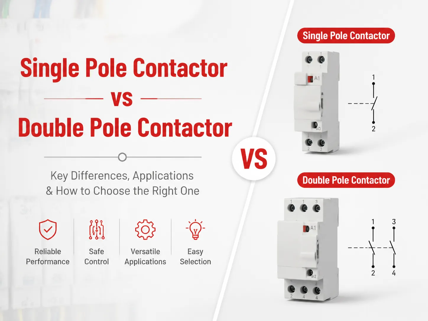

DIN, Deutsche Industrie Norm'un kısaltmasıdır. DIN 46277, Top Şapka Rayının profilini simetrik olarak tanımlar, böylece elektrikli cihazlar, cihazı her kenardan ne kadar uzaklıkta hizalamanız gerektiği konusunda endişelenmeden kolayca monte edilebilir. Orijinal standart, Referans Standart ile ilgili olarak EN 50022'ye ve ardından IEC 60715'e uyarlanmıştır.
The → The 35 mm Ray Boyutu, 35 mm ray genişliğinin Tompson bağlantısını güvenli hale getiren stabil bir klips sağlaması ve devre kesiciler serisi arasında birliği mümkün kılması nedeniyle en çok kullanılan ve popüler ray boyutu haline gelmiştir; aynı zamanda kompakt kalmalarını sağlamıştır – 35 mm raylı 12 yollu bir panonun gerçek genişliği yaklaşık 210 mm'dir, bu format yaklaşık 250 mm genişliğinde bir muhafazaya sığar, bundan daha geniş olanlar değerli muhafaza alanını boşa harcar, bundan daha dar olanlar ise terminal torku uygulandığında 63 A dereceli bir cihazı güvenli şekilde tutamaz.
Bulunabilen diğer ray genişlikleri 15 mm'dir, bunlar tarihsel olarak bugün kontrol panellerinde hala kullanılan minyatür terminal blokları için kullanılmıştır. 75 mm ray, ağır sanayi ekipmanları ve büyük terminal montajları için tasarlanmıştır. Devre kesiciler ve diğer cihazlar birbirleriyle herhangi bir şekilde ilişkili değildir, ancak her iki öğe aynı katalogda yer aldığı için karışıklık yaratmıştır.
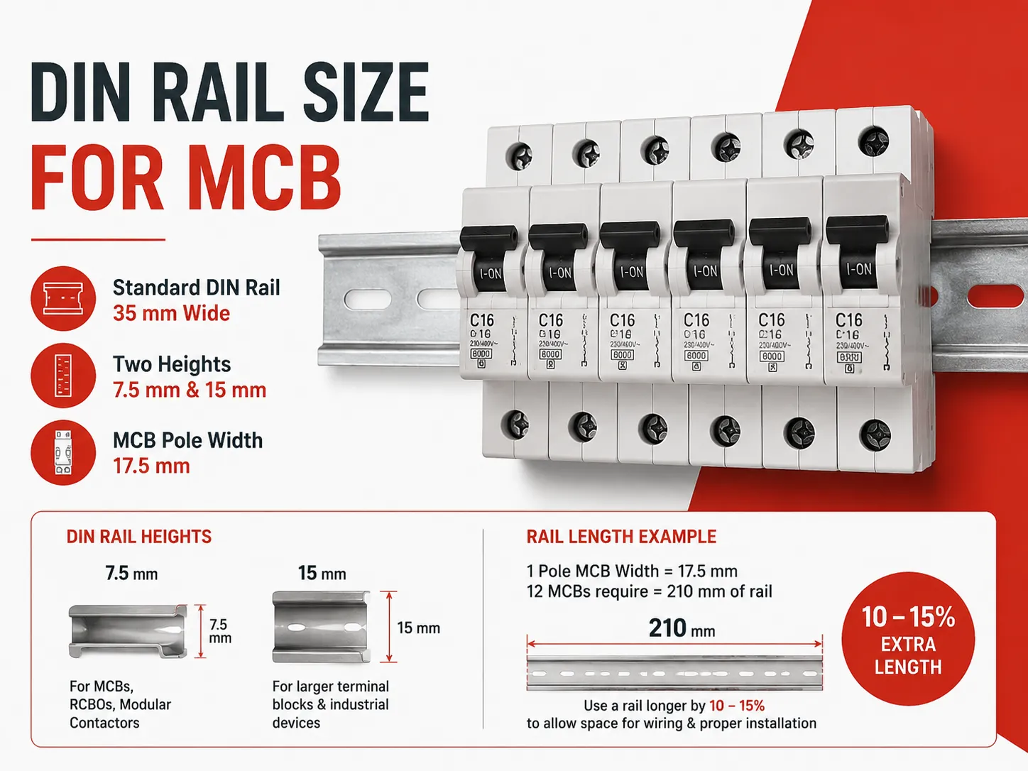
Hızlı cevap: Her MCB, IEC/EN 60715 tarafından belirtilen 35 mm genişliğindeki bir raya bağlanır. Bu profil iki farklı yükseklikte gelir – 7.5 mm ve 15 mm. Daha küçük versiyon (7.5 mm) MCB'ler, Artık Akım Devre Kesicileri (RCBO'lar) ve modüler kontaktörler için kullanılır. Daha büyük versiyon (15 mm) daha büyük terminal blokları ve endüstriyel cihazlar için ek dayanıklılık sağlar. Bir MCB'nin bir kutbunun genişliği 17.5 mm'dir, bu nedenle on iki MCB içeren bir pano, onları monte etmek için 210 mm ray gerektirir; bu, MCB'lerin düzgün şekilde bağlanmasını engellemeden monte edilmesini sağlamak için kullanılan rayın ila daha büyük olması gerektiği anlamına gelir.
IEC 60715'in Belirttikleri
IEC 60715 bir rayın boyutunu, kalınlığını ve toleranslarını belirler. Bu standart sayesinde, bir üretici tarafından yapılan bir ray, başka bir üretici tarafından yapılan cihazlarla uyumludur. Bir kurulumcunun ray kullanırken önem verdiği tek boyutlar rayın genişliği (35 mm), profil yüksekliği (7.5 mm veya 15 mm) ve kalınlığıdır (7.5 mm profil için genellikle soğuk haddelenmiş çelikten yapılmış 1 mm kalınlığındadır).
Bir cihazın arkasında bulunan klips, yaylı olacak şekilde tasarlanmıştır ve rayın ön dudağı altına kendini sabitleyip ardından rayın arka kenarının üzerinden geçerek tutunur. Klipsin hareket mesafesi önemlidir, çünkü sadece 7.5 mm profil yüksekliği için üretilmiş cihazlar, yeterli hareket mesafesine sahip oldukları sürece 15 mm profil yüksekliğine sahip bir raya klipslenebilir. Tersine, 15 mm profil için tasarlanmış bir cihaz, 7.5 mm profil rayına kötü oturur. Bu iki tip cihazın aynı muhafaza içinde yanlış karıştırılması, elektronik cihazların amaçlanan pozisyonlarına göre eğik görünmelerinin yaygın bir nedenidir.
Arayüzün cihaz tarafı kısmının standardizasyonu DIN 43880 ile de mevcuttur. Bu standart, modüler elektronik cihazların genel boyutlarını belirler. Modüler bir cihaz, tam bir modül için 80 mm yüksekliğe sahip olarak tanımlanır. Modüler bir cihaz ayrıca yarım modül olarak da tanımlanabilir, yani 45 mm. DIN 43880 standardında belirtilen modüler cihazların genişlik ızgarası da 17.5 mm olarak tanımlanmıştır. Bu nedenle, 6 ila 63 A akım değerine sahip bir EXB3 miniature devre kesici tam olarak bir modül kaplar ve DIN 43880 ray montajlı cihazların standardizasyonunu sağladığından, başka bir üretici tarafından üretilmiş bir terminal bloğu veya zaman rölesi ile aynı raya takılabilir.
5 mm vs 15 mm: Hangi Profil Seçilmeli?
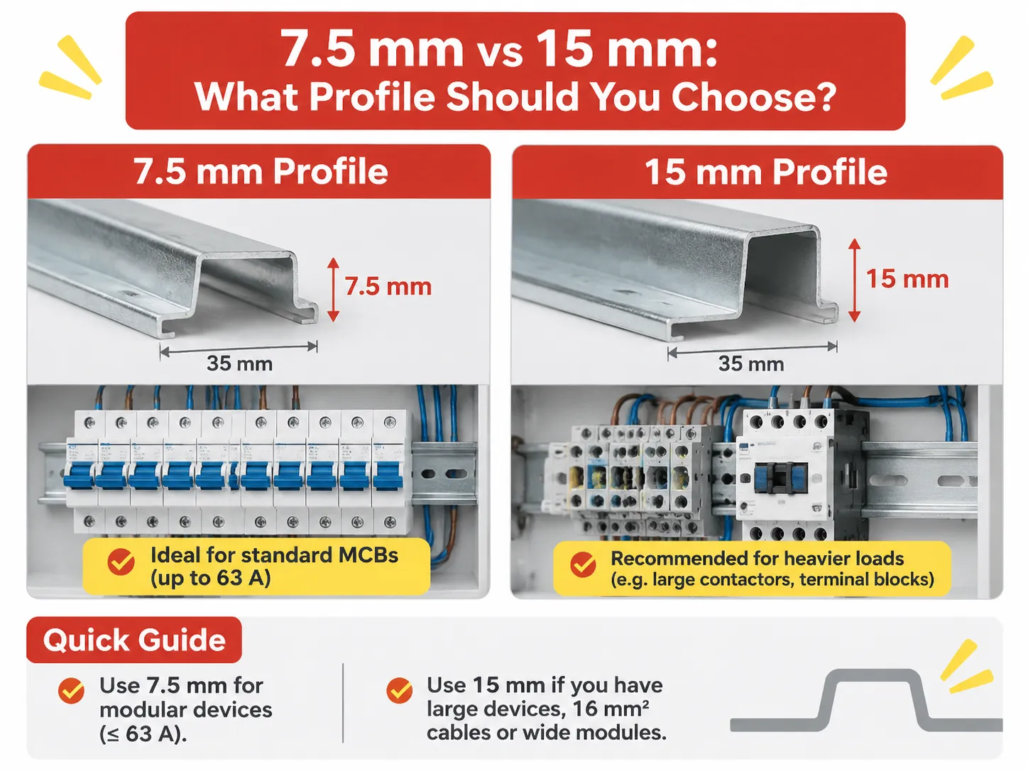
5 mm profil, inceliği, düşük fiyatı ve birden fazla devre kesiciyi tutma gücü nedeniyle tüm tüketici üniteleri ve dağıtım panolarında standart olarak kullanılır; muhafaza genellikle rayın her iki ucunu destekler ve ortada ek bir destek bulunur.
15 mm profil, 7.5 mm profil ile aynı 35 mm genişliğe sahip, üst şapka tarzı profilin büyütülmüş versiyonudur; ray üzerindeki yük devre kesicilerden daha ağır olduğunda kullanılır, örneğin ağır terminal blokları, daha büyük kontaktörler, grup başlatıcılar veya sürekli kullanılan cihazlar (yani aç-kapa) olabilir. Bu profilin ekstra kalınlığı, aksi takdirde sorun yaratabilecek burulma yüklerine dayanmasını sağlar.
Bir pano üreticisi için pratik bir kural; eğer bir sırada sadece 63 A'ye kadar derecelendirilmiş modüler cihazlar varsa, 7.5 mm profil yeterli olacaktır; ancak o sırada 16 mm² kablolu terminal blokları varsa veya 4 modülden daha geniş ekipman varsa, 15 mm profil kullanılmalıdır. Karışık modüller varsa, en büyük klipse sahip cihaz, hangi profilin grup için en uygun olacağını belirleyecektir; ancak diğer modüller büyük tasarımla muhtemelen hala uyumludur.
| Cihaz | Kutup | Genişlik | Modüller |
|---|---|---|---|
| Tek kutuplu Miniature Devre Kesici (MCB) | 1 Kutup | 5 mm | 1 Modül |
| Nötr anahtarlamalı Miniature Devre Kesici | 1 Kutup + Nötr | 35 mm | 2 Modül |
| Çift kutuplu Miniature Devre Kesici | 2 Kutup | 35 mm | 2 Modül |
| Üç kutuplu Miniature Devre Kesici | 3 Kutup | 5 mm | 3 Modül |
| Dört kutuplu Miniature Devre Kesici | 4 Kutup | 70 mm | 4 Modül |
| Artık Akım Devre Kesici (RCBO) tek modül | 1 Kutup + Nötr | 17,5 – 18 mm | 1 Modül |
| Artık Akım Devre Kesici (RCBO) iki modül | 1 Kutup + Nötr | 35 mm | 2 Modül |
| Artık Akım Devre Kesici (RCCB)(2P, 4P) | 2 Kutup veya 4 kutup | 35 mm veya 70 mm | 2 Modül veya 4 Modül |
Aşağıdaki her iki satır da uyarılar içerir. Tek modül RCBO, artık akım ve aşırı akım korumasını bir Miniatür Devre Kesici alanına sığdırdığı için çok kullanışlı bir üründür. Bu nedenle, günümüzde bir tüketici ünitesi 140 mm genişlikte sekiz RCBO alabilirken, önceki tasarımlarda sekiz RCBO artı ana RCCB ile 210 mm genişlikteydi; iki modül versiyonu daha eski tasarımlarda ve/veya 32 A üzeri değerler için, mekanizmanın alan gerektirmesi nedeniyle daha yaygındır.
Bu Tablo'daki cihazların kutup sayısı, tipik olarak bir MCB serisinin fiziksel ölçülen boyuttan çok modül sayısına göre tanımlanmasının nedenidir. Bir pano programı “12 yol” dediğinde, bu, rehber rayına cihaz takmak için mevcut on iki modülü ifade eder, toplam on iki cihazı değil. Bu nedenle, bir tasarımcı tüm on iki konumu tek kutuplu MCB'lerle doldurup ayrıca bir artık akım cihazı (RCD) eklerse, tüketici ünitesinin tüm rehber rayını cihazlarla doldurmuş olur.
Şimdi Sahip Olduğunuz Rayı Ölçme
Bir tüketici ünitesi rehber rayını, aşağıda listelenen üç ray tanımlayıcısını bir cetvel kullanarak otuz saniyeden kısa sürede ölçebilirsiniz. Genişlik: şapkanın düz yüzünün merkezinden karşı düz yüzün merkezine kadar ölçün; bu ölçüm genellikle rayın her düz yüzü boyunca yaklaşık 35 mm'dir.
Profil yüksekliği (standart ray yaklaşık 7,5 mm ve derin versiyonda 15 mm olarak okunur), profilin düz yüzü ile dudak altı arasındaki mesafeyi ölçer. Profil kalınlığı genellikle çelik profilden ölçülür, çünkü çelik diğer profillere göre daha kalındır ve ölçümü zorlaştırır, ayrıca kullanım sırasında genellikle ölçülemez.
Genişlik 32 mm ise = G Profil, asimetrik (bölümlü) Amerikan ve İngiliz ekipmanlarında kullanılan ve bazı endüstriyel panellerde hâlâ bulunan raydır. Bu nedenle, G-Ray Cihazları 35 mm profiline uymaz. Dolayısıyla, bir G-ray Cihazını Standart 35 mm Ray için bir Cihazla değiştirmek istiyorsanız, G-ray'i Standart 35 mm Ray ile eşleştirmeniz gerekir.
Dördüncü olarak, montaj yöntemleri ya sabit ya da bir kabinin arka plakasına klipslenmiş olabilir. Sabit yöntem değiştirilebilir veya genişletilebilir; ancak klipsli yöntem muhtemelen değiştirilemez, çünkü destek kabin kalıbı tarafından oluşturulur. Bu, bir panonun yerinde yükseltilebilip yükseltilemeyeceğini veya tüm ünitenin bir bütün olarak değiştirilmesi gerekip gerekmediğini etkiler.
Bir Pano için Ray Nasıl Boyutlandırılır
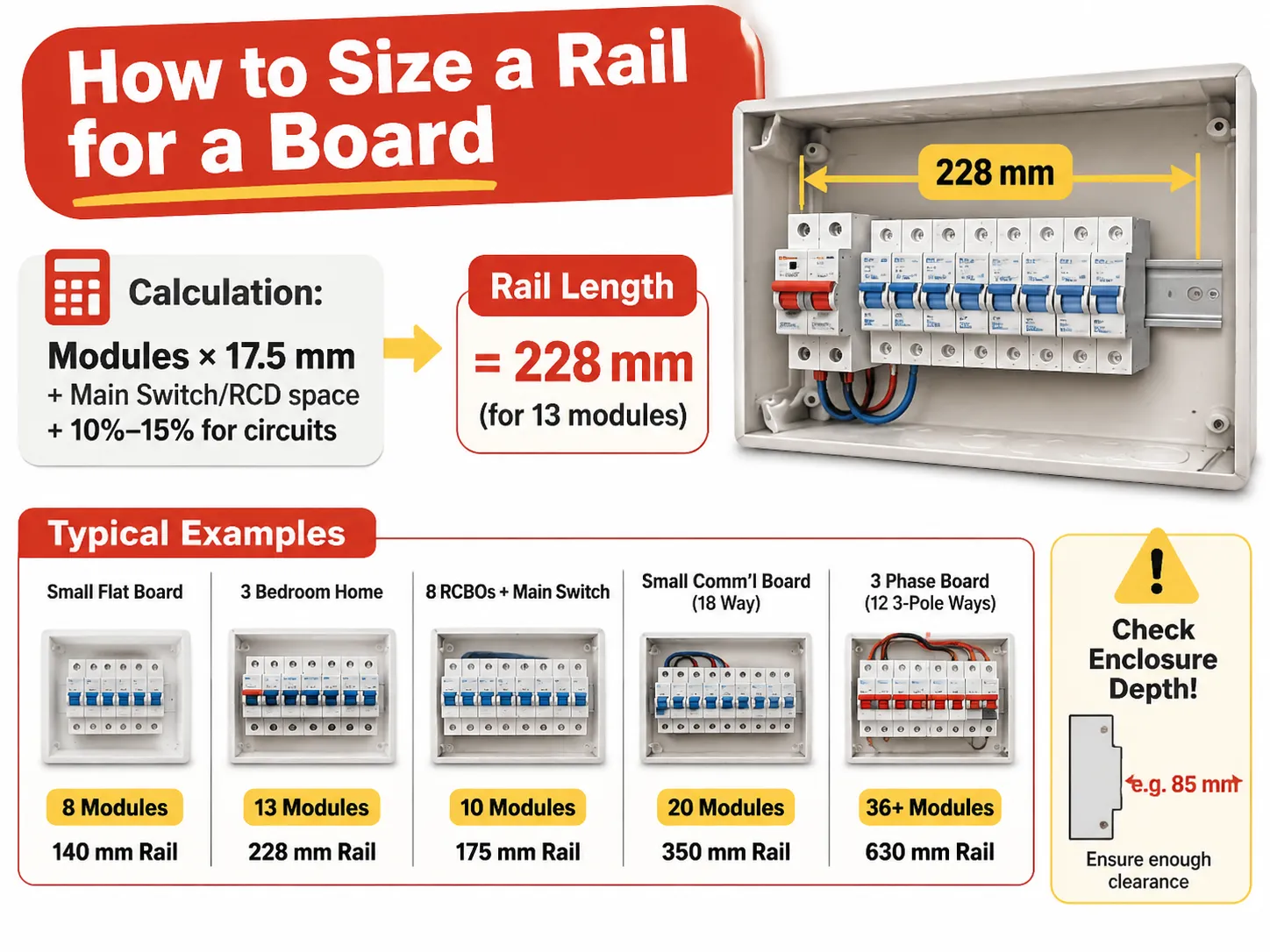
Bir Panoya Ray Nasıl Boyutlandırılır Hesaplaması, genel hesaplamalar, Program MM'den Modül sayısını kullanarak ve 17,5 MM ile çarparak (+ marj) hesaplama aritmetik yöntemine dayanır, Ana Şalter/RCD alanı henüz sayılmamışsa eklenir ve pano teslim edildiğinde görünecek Devreler için +10%-15% eklenir.
| Pano | Modules required | Rail length | Typical enclosure width |
|---|---|---|---|
| Small Flat Board | 8 Modules | 140mm Rail | 200mm Enclosure (8-10 way) |
| 3 Bedroom Home | 1 Main Switch, 10 MCB’s, 13 Modules | 228mm Rail | 250mm Enclosure (12-14 way) |
| House with 8 RCBO’s and a Main Switch | 10 Modules | 175mm Rail | 230mm Enclosure (10-12 way) |
| Small Comm’l Board (18 way) | 20 Modules | 350mm Rail | 400mm Enclosure (18-21 way) |
| 3 Phase Board (12 3-Pole Ways with Main) | 36 or More (plus Main) | 630mm Rail | 700mm Enclosure (2 Rows) |
The → The enclosure width differs from the rail length, and this creates confusion for people ordering from a catalogue. A “12 way” board has 12 usable module spaces on the rail that are 250mm wide, because the rail is clipped between two end supports, and the enclosure doorframe takes the rest of the space.
Enclosure depth and height determine the space available for installation and do not depend on the enclosure width. For example, with 200 mm’s of usable rail and 100 depths of the enclosure, you will not be able to close the enclosure over an 85mm device projecting from the rail, once the wire is connected. Once the physical dimensions of the electrical box are verified that it is in acceptable limits (height and depth), the electrical box should be checked for clearance against the device’s physical dimensions prior to ordering a board. The ONLY TIME this error occurs is during the actual installation of a board in question.
Does the Rail Vary by Country?
The Rail DO NOT VARY by Country. The 35mm (IEC 60715) rail is widely used throughout the world, so there is no difference between 35mm rail purchased in China (Shanghai) compared to 35mm rail purchased in Western Europe (Rotterdam).
Differences exist on how the equipment will be installed and the differences lead to three separate and distinct areas for the homeowner.
North America has the greatest difference as a North American residential load centre is a proprietary enclosure (fully enclosed) that generally has no DIN Rail at all as the breakers clip directly to the busbar/stab-on type busbars. When DIN Rail appears in Commercial and Industrial work in North America, the standard rail width is 35 mm and in photovoltaic (solar) and Control Panels it is becoming more and more common. Older equipment may have used the 32 mm G-rail.
The British Isles and Ireland have been using the 35 mm DIN rail for many of their more modern Consumer Units; however, many fuse boards from the 1970s and early 1980s used a different mounting method; therefore, an RCBO intended for a fuse board from the 1980s may require an adapter for mounting to a modern Consumer Unit. Australia and New Zealand have been following the IEC standard using 35 mm rail and have developed 17.5 mm wide modules and their breakers are the same as those in Europe. Some Japanese manufacturers are producing breakers and accessories that follow the same basic specifications as European models, and they also use 35 mm rail and JIS tolerances can be compatible for practical application. India, the Middle East, and South East Asia are all fully IEC compliant.
The other major distinction between regions is not with respect to the size of the rail but the size of the actual DEVICE. A single break load centre in North America is approximately 25 mm wide and 1 inch thick per pole, therefore, it has an entirely different dimension form factor; therefore, a panel built for the North American market will not accommodate IEC modular devices, and the decision on rail size will only be made after the project has adopted the IEC system for installation.
Rail Material, Thickness and Why Cheap Rails Fail
The rail is manufactured from Cold Rolled Steel which is Zinc Plated, with a thickness of 1mm for 7.5mm Profile and typically 1.5 to 2mm for deeper profiles. The plating of the rail is important because rail is a conductive path during a fault, and Zinc plated rails will not rust at the mounting holes for approximately 2 years when installed in a moist environment such as plant rooms.
Aluminium rail should not be used for breaker rows. When using an aluminium rail, the aluminium rail will deform under concentrated load when a device’s clip is being removed by way of lever action. Once an aluminium rail has been deformed, the devices will no longer fit square in the rail and also the busbar comb will not align properly. Thus, if an aluminium rail is used, it will be necessary to remove and dispose of the entire rail and all of the devices in order to rebuild the row.
THICKNESS of rail is also a point of failure. RAIL that is 0.6mm thick will flex due to the forces applied from the installation of the devices. This flex will cause the clips to be raised slightly when the devices are installed, causing the devices to appear seated when in fact they are not. This is particularly significant in 36-module, three-phase rows, which is the reason that deep profile rails are manufactured for applications requiring long lengths of rail.
Cutting, Mounting and Clearance
Rails are available in lengths of one meter and two meters. Rails may be cut at the installation site using a hacksaw or a angle grinder. The two most important criteria for ensuring a good cut are to ensure that the rail is cut square along its length and to ensure that both ends of the newly cut section of rail are deburred.A burr on the lip of that device will stop it from clipping onto the rail and lead to a natural reaction of forcing it in place, which in turn causes the rail to bend.
It is important to allow for end stops to have a clearance of approximately 2-3mm at either end due to their load-bearing function rather than just being cosmetic. A row of breakers without end stops can slide sideways, and a row of sliding devices will pull the busbar combing off alignment. It is, therefore, normal practice to use an end stop at each end of a rail which carries more than 10 devices, in addition to one located in the middle of the rail.
The clearance for wiring is most often neglected. Devices extend 70-75mm forward from the rail face and, within the device’s enclosure, the cables will need to bend, therefore the board needs to provide 60mm of clear space above the rail for the incoming side, and the same space below. An RCBO subjected to a shallow enclosure will not provide adequate clearance for bending of the cable, resulting in either a cover that will not close or a pinched cable.
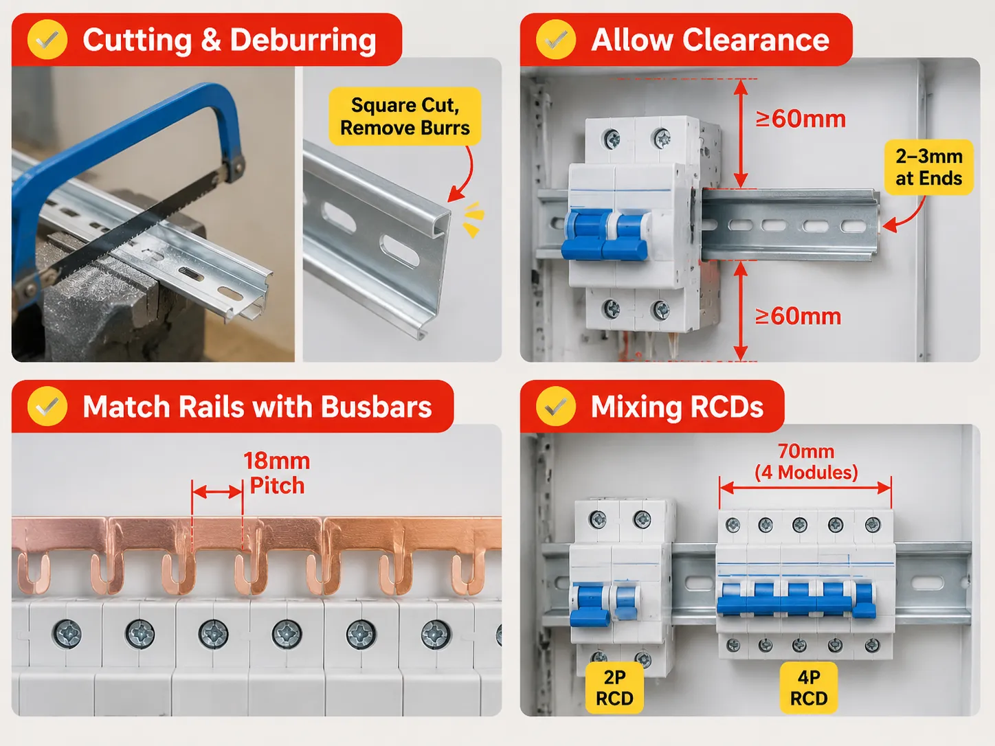
Rails and Enclosures Must Be Matched with Busbars
Devices are positioned on the rails and connected by comb busbars. The busbars have fixed 18mm pitch positions, which consists of 17.5mm module plus the clearance. Care must be taken when working with mixed rows as the busbars with an 18mm pitch will not align with devices that each have an 18mm width because of each having slightly different seating positions. The busbars will not span 2-module RCBOs properly; a gap will occur. A module row should first be designed using modules, and then designed using devices in the same manner that it will eventually be used. This allows for more flexibility when ordering busbar, as it will be ordered according to how many of each type of device it needs, rather than how many busbars can fit into the enclosure.
When a row has both two-pole and four-pole residual devices located in the same row, the pitch mechanics change again. The range of residual current devices can differ significantly in the number of modules included between designs. For example, a four-pole RCCB for a three-phase panel board requires 70 mm. This equates to four circuits that cannot be used for outgoing circuits.
How HUYU Connects
Our modular devices are created with a 17.5 mm module and a 35 mm rail interface, thus determining whether a panel board can be built from the use of multiple brands without needing to rework them. The EXB3 series provides full coverage for B, C and D curve ratings of 6, 8, 10, 15, 20, 25, 32, 40, 50, 63 amp ratings at 6 kA, in single, double, triple and quadruple pole configurations, using the same clip geometry across the range, allowing rows of the devices to be installed without shimming.
By comparison, the EXM3 moulded case breaker can provide service from 16 amp to 250 amp ratings and is an entirely different mounting class; this device is installed by mounting to a plate, instead of clipping on to a rail. It is prudent to understand this difference when a panel board is being drawn, as it is an appropriate assumption that all devices will be modular; this transition typically occurs around 125 amps, which is where the panel board stops becoming a Consumer Unit and becomes a Switchboard. When we make an inquiry about a board, we are asking for three things: The module count, pole configuration, and enclosure width. These three values determine rail, busbar and way counts respectively; if they are not provided with your request, your quotation will reflect only the cost of a product and not the board itself.
Sıkça Sorulan Sorular
What is the standard size of a DIN Rail?
The DIN Rail is defined as 35mm wide, using a top-hat profile as per IEC/EN 60715, with a height of either 7.5mm (used in conjunction with MCBs or modular devices) or 15mm (used in conjunction with heavier terminal blocks or industrial equipment). Other widths exist. Specifically, 15mm and 75mm, but neither of these is used in conjunction with MCBs.
What is DIN Rail for MCB?
The DIN Rail is the metal channel that the MCB clips onto when placed inside an enclosure. It is the clip that is located on the back side of the MCB that hooks under the front lip of the DIN Rail and snaps over the rear side of the DIN Rail, allowing for the fitting and removal of the MCB without using any kind of tool after isolating the supply.
How wide are DIN Rail circuit breakers by pole?
The width of a single pole DIN Rail circuit breaker is 17.5 mm which equals one module. A double pole circuit breaker will be 35 mm, a three-pole circuit breaker will be 52.5 mm and a four-pole circuit breaker will be 70 mm. A single-module RCBO will be the same 17.5 mm as for the other types of circuit breakers. A two-module version will be 35 mm.
How do you size a DIN Rail?
To determine the size of a CMX enclosure, you multiply the number of modules required by 17.5 mm; this calculation gives you the total usable height of your enclosure. You add an additional 10-15% to the base of the board to allow for future circuits. The height of the usable rail on a 12-way CMX is approximately 210 mm when the enclosure is approximately 250 mm wide.
Is DIN rail used in the same way in all countries?
Approximately 35 mm of usable DIN rail is the standard throughout most of the world according to IEC 60715. The main differences between countries are historical – North America’s residential load centre designs use a proprietary stab-on busbar system which does not use DIN rail, whereas older versions of American and British panel boards were designed to work with a 32 mm G-rail. Older British Panel Boards utilised a British G-rail, while the newer styles now require an adaptator in order to be used with a new style of device.
Is it possible to fit a device with a 15 mm raised profile onto a 7.5 mm base?
Typically not in a secure manner. The device is not designed to fit onto a shallow mount, and the mounting clips on the deeper mount will allow more travel than the shallow mount will accommodate; thus, the device sits loosely and can easily be removed from the rail by a cable pull. To ensure a secure fit, always match the mounted device to the mount profile, or replace the mount.
Referanslar
- Siemens, Modular Devices and DIN Rail Mounting
- ABB, Modular Devices and associated rail kits for mounting according to DIN standard
- Hager, Consumer Unit Dimensions
- Phoenix Contact, manufacturer of DIN Rail Modular Device and Terminal Block Systems
- Electrical Engineering Portal, Design Layout of Panelboards and Modular Devices
Sonuç
To sum up, the number 35 mm has been used as a standard mount for CMX enclosures for 35 years. The only differences between the installation/usage is the height of the mounts between installed CMX boards (7.5 mm and 15 mm). In essence, you simply change the physical mounting to install this type of device in an older style of panelboard.