
DIN — это сокращение от Deutsche Industrie Norm. DIN 46277 определяет профиль рейки типа «Top Hat» как симметричный, что позволяет легко монтировать электрические устройства без необходимости учитывать расстояние от каждого края для выравнивания устройства. Исходный стандарт был гармонизирован в EN 50022, а затем в IEC 60715 в отношении эталонного стандарта.
Тот 35 мм Размер рейки стал самым используемым и популярным, поскольку ширина рейки 35 мм обеспечивала стабильное крепление для соединения Томпсона и позволяла унифицировать диапазон автоматических выключателей, сохраняя их компактность — фактическая ширина платы на 12 модулей с рейкой 35 мм составляет примерно 210 мм, этот формат помещается в корпус шириной около 250 мм, при этом более широкий корпус приводит к потере ценного пространства, а более узкий не обеспечивает надежного крепления устройства с номиналом 63 А при приложении крутящего момента к клеммам.
Другие ширины реек, которые можно встретить, — 15 мм, которые исторически использовались для миниатюрных клеммных колодок, которые до сих пор применяются в щитах управления. Рейка шириной 75 мм предназначена для тяжелого промышленного оборудования и крупных клеммных сборок. Автоматические выключатели и другие устройства не связаны друг с другом, но оба типа изделий включены в один каталог, что создавало путаницу.
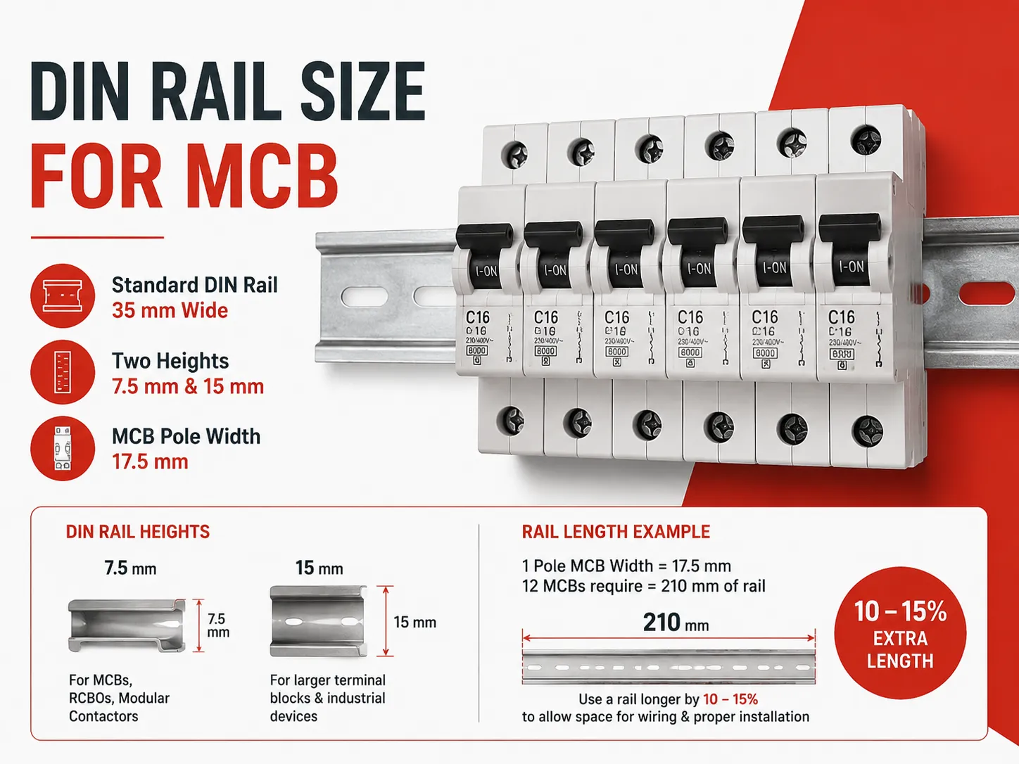
Краткий ответ: Каждый автоматический выключатель (MCB) крепится к рейке шириной 35 мм, как указано в IEC/EN 60715. Этот профиль выпускается в двух вариантах высоты — 7,5 мм и 15 мм. Меньшая версия (7,5 мм) используется для MCB, дифференциальных автоматов (RCBO) и модульных контакторов. Большая версия (15 мм) обеспечивает дополнительную прочность для крупных клеммных колодок и промышленного оборудования. Ширина одного полюса MCB составляет 17,5 мм, поэтому плата с двенадцатью MCB требует 210 мм рейки для монтажа, что означает, что используемая рейка должна быть на 10–15 процентов шире, чтобы обеспечить монтаж MCB без препятствий для подключения проводов.
Что специфицирует IEC 60715
IEC 60715 определяет размер, толщину и допуски рейки. Благодаря этому стандарту рейка, изготовленная одним производителем, совместима с устройствами другого производителя. Единственные размеры, которые важны для монтажника при использовании рейки, — это ширина рейки (35 мм), высота профиля (7,5 мм или 15 мм) и толщина (для профиля 7,5 мм обычно 1 мм, изготовленная из холоднокатаной стали).
Клипса, расположенная на задней стороне устройства, спроектирована с пружинным механизмом и фиксируется под передним выступом рейки, затем защёлкивается за задний край рейки. Длина хода клипсы важна, так как только устройства, предназначенные для использования с высотой профиля 7,5 мм, могут быть закреплены на рейке с высотой профиля 15 мм при условии достаточного хода. Напротив, устройство, предназначенное для использования с профилем 15 мм, плохо подходит для рейки с профилем 7,5 мм. Неправильное смешивание этих типов устройств в одном корпусе является распространённой причиной того, что электронные устройства устанавливаются под углом к их предполагаемому положению.
Стандартизация боковой части интерфейса устройства также существует в DIN 43880. Этот стандарт устанавливает общие размеры модульных электронных устройств. Модульное устройство определяется как имеющее высоту 80 мм для полного модуля. Модульное устройство также может быть определено как полумодуль, то есть 45 мм. Ширина сетки модульных устройств, как указано в стандарте DIN 43880, также определяется как 17,5 мм. Следовательно, миниатюрный автоматический выключатель EXB3 с номинальным током от 6 до 63 А занимает ровно один модуль, и поскольку DIN 43880 обеспечивает стандартизацию устройств для монтажа на рейку, он также сможет крепиться к той же рейке, что и клеммная колодка или таймерное реле, изготовленные другим производителем.
7,5 мм против 15 мм: какой профиль выбрать?
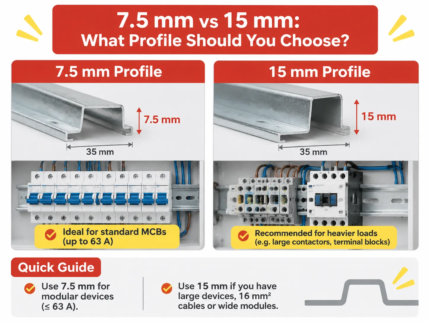
Профиль 7,5 мм используется как стандарт во всех потребительских блоках и распределительных щитах благодаря своей тонкости, низкой цене и прочности для удержания нескольких автоматических выключателей; корпус поддерживает оба конца рейки, обычно с дополнительной опорой посередине.
Профиль 15 мм является увеличенной версией профиля типа «шляпка», с той же шириной 35 мм, что и профиль 7,5 мм, используется там, где нагрузка на рейку тяжелее, чем у автоматических выключателей, например, могут быть ряды тяжёлых клеммных колодок, больших контакторов, групповых пускателей или аппаратов, используемых непрерывно (то есть включение и выключение). Дополнительная толщина этого профиля позволяет ему выдерживать крутящие нагрузки, которые в противном случае могли бы вызвать проблемы.
Практическое правило для изготовителя щитов: если в ряду только модульные устройства с номиналом до 63 А, то профиль 7,5 мм будет подходящим; однако, если в этом ряду есть клеммные колодки с кабелями 16 мм² или оборудование шире 4 модулей, следует использовать профиль 15 мм. В случаях смешанных модулей решающим фактором будет устройство с самой большой клипсой, определяющее, какой профиль лучше всего подходит для группы; однако остальные модули, скорее всего, также совместимы с более крупным дизайном.
| Устройство | Полюса | Ширина | Модули |
|---|---|---|---|
| Однополюсный миниатюрный автоматический выключатель (MCB) | 1 полюс | 17,5 мм | 1 модуль |
| Миниатюрный автоматический выключатель с переключаемым нейтральным проводом | 1 полюс + нейтраль | 35 мм | 2 модуля |
| Двухполюсный миниатюрный автоматический выключатель | 2 полюса | 35 мм | 2 модуля |
| Трёхполюсный миниатюрный автоматический выключатель | 3 полюса | 52,5 мм | 3 модуля |
| Четырёхполюсный миниатюрный автоматический выключатель | 4 полюса | 70 мм | 4 модуля |
| Устройство защитного отключения с функцией автоматического выключателя (RCBO) на один модуль | 1 полюс + нейтраль | 17,5 – 18 мм | 1 модуль |
| Устройство защитного отключения с функцией автоматического выключателя (RCBO) на два модуля | 1 полюс + нейтраль | 35 мм | 2 модуля |
| Устройство защитного отключения (RCCB)(2P, 4P) | 2 полюса или 4 полюса | 35 мм или 70 мм | 2 модуля или 4 модуля |
Обе приведённые ниже строки требуют оговорок. RCBO на один модуль — очень полезный продукт, поскольку он объединяет защиту от остаточного тока и перегрузки в пространстве одного миниатюрного автоматического выключателя. Благодаря этому сегодня в распределительном щите можно разместить восемь RCBO шириной 140 мм, в то время как ранее восемь RCBO плюс основной RCCB занимали ширину 210 мм; версия на два модуля гораздо более распространена в старых конструкциях и/или для номиналов свыше 32 А, которые требуют дополнительного пространства для механизма.
Количество полюсов устройств в этой таблице является причиной того, что обычно ассортимент автоматических выключателей определяется в первую очередь по количеству модулей, а не по физическому размеру. Когда в схеме щита указано “12 модулей”, это означает двенадцать доступных модулей для крепления устройств на направляющую рейку, а не двенадцать устройств в целом. Следовательно, если проектировщик заполнит все двенадцать мест однополюсными автоматическими выключателями, а затем добавит устройство защитного отключения (RCD), он/она уже полностью заполнит направляющую рейку распределительного щита устройствами.
Измерение направляющей рейки, которая у вас есть
Вы можете измерить направляющую рейку распределительного щита, измерив три параметра, указанных ниже, менее чем за тридцать секунд с помощью линейки. Ширина: измеряется от центра плоской поверхности шляпки до центра противоположной плоской поверхности; это измерение обычно составляет примерно 35 мм по каждой плоской поверхности рейки.
Высота профиля (стандартная рейка примерно 7,5 мм, глубокая версия — 15 мм) измеряет расстояние между плоской поверхностью профиля и нижней стороной выступа. Толщина профиля обычно измеряется по стальному профилю, поскольку сталь обычно толще других профилей, что затрудняет измерение и обычно не поддаётся измерению в процессе эксплуатации.
Если ширина равна 32 мм = профиль G, асимметричный (с секциями). Рейка используется в старом американском и британском оборудовании и всё ещё доступна в некоторых промышленных щитах. Следовательно, устройства для G-рейки не подойдут для профиля 35 мм. Если вы хотите заменить устройство для G-рейки на устройство для стандартной 35 мм рейки, вам нужно сопоставить G-рейку со стандартной 35 мм рейкой.
Четвёртый момент — методы крепления: либо фиксированные, либо защёлкивающиеся на задней панели шкафа. Фиксированный метод можно заменить или расширить; однако защёлкивающийся метод, вероятно, нельзя, поскольку опора формируется корпусом шкафа. Это влияет на возможность модернизации щита на месте или необходимость полной замены всего блока.
Как подобрать размер рейки для щита
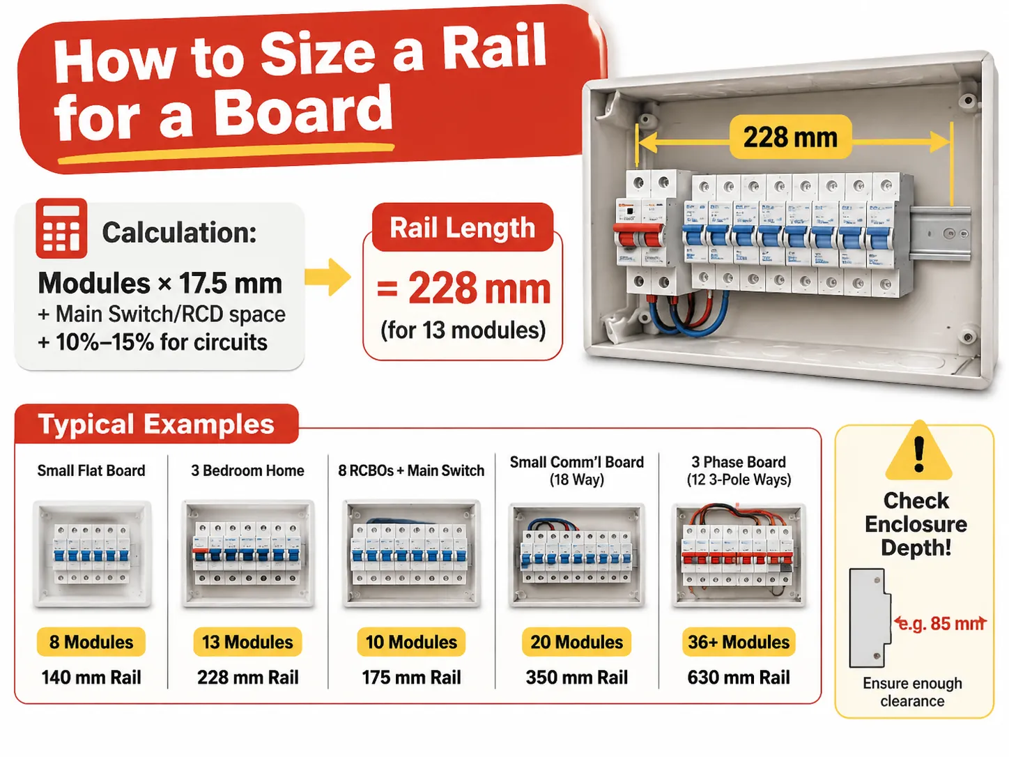
Расчет того, как определить размер рейки для щита, основан на арифметическом методе вычисления (+ запас) с использованием количества модулей из расписания MM и умножением на 17,5 мм, добавлении места для главного выключателя/УЗО, если оно еще не учтено, и добавлении +10%-15% для цепей, которые появятся при передаче щита.
| Щит | Modules required | Rail length | Typical enclosure width |
|---|---|---|---|
| Small Flat Board | 8 Modules | 140mm Rail | 200mm Enclosure (8-10 way) |
| 3 Bedroom Home | 1 Main Switch, 10 MCB’s, 13 Modules | 228mm Rail | 250mm Enclosure (12-14 way) |
| House with 8 RCBO’s and a Main Switch | 10 Modules | 175mm Rail | 230mm Enclosure (10-12 way) |
| Small Comm’l Board (18 way) | 20 Modules | 350mm Rail | 400mm Enclosure (18-21 way) |
| 3 Phase Board (12 3-Pole Ways with Main) | 36 or More (plus Main) | 630mm Rail | 700mm Enclosure (2 Rows) |
Тот enclosure width differs from the rail length, and this creates confusion for people ordering from a catalogue. A “12 way” board has 12 usable module spaces on the rail that are 250mm wide, because the rail is clipped between two end supports, and the enclosure doorframe takes the rest of the space.
Enclosure depth and height determine the space available for installation and do not depend on the enclosure width. For example, with 200 mm’s of usable rail and 100 depths of the enclosure, you will not be able to close the enclosure over an 85mm device projecting from the rail, once the wire is connected. Once the physical dimensions of the electrical box are verified that it is in acceptable limits (height and depth), the electrical box should be checked for clearance against the device’s physical dimensions prior to ordering a board. The ONLY TIME this error occurs is during the actual installation of a board in question.
Does the Rail Vary by Country?
The Rail DO NOT VARY by Country. The 35mm (IEC 60715) rail is widely used throughout the world, so there is no difference between 35mm rail purchased in China (Shanghai) compared to 35mm rail purchased in Western Europe (Rotterdam).
Differences exist on how the equipment will be installed and the differences lead to three separate and distinct areas for the homeowner.
North America has the greatest difference as a North American residential load centre is a proprietary enclosure (fully enclosed) that generally has no DIN Rail at all as the breakers clip directly to the busbar/stab-on type busbars. When DIN Rail appears in Commercial and Industrial work in North America, the standard rail width is 35 mm and in photovoltaic (solar) and Control Panels it is becoming more and more common. Older equipment may have used the 32 mm G-rail.
The British Isles and Ireland have been using the 35 mm DIN rail for many of their more modern Consumer Units; however, many fuse boards from the 1970s and early 1980s used a different mounting method; therefore, an RCBO intended for a fuse board from the 1980s may require an adapter for mounting to a modern Consumer Unit. Australia and New Zealand have been following the IEC standard using 35 mm rail and have developed 17.5 mm wide modules and their breakers are the same as those in Europe. Some Japanese manufacturers are producing breakers and accessories that follow the same basic specifications as European models, and they also use 35 mm rail and JIS tolerances can be compatible for practical application. India, the Middle East, and South East Asia are all fully IEC compliant.
The other major distinction between regions is not with respect to the size of the rail but the size of the actual DEVICE. A single break load centre in North America is approximately 25 mm wide and 1 inch thick per pole, therefore, it has an entirely different dimension form factor; therefore, a panel built for the North American market will not accommodate IEC modular devices, and the decision on rail size will only be made after the project has adopted the IEC system for installation.
Rail Material, Thickness and Why Cheap Rails Fail
The rail is manufactured from Cold Rolled Steel which is Zinc Plated, with a thickness of 1mm for 7.5mm Profile and typically 1.5 to 2mm for deeper profiles. The plating of the rail is important because rail is a conductive path during a fault, and Zinc plated rails will not rust at the mounting holes for approximately 2 years when installed in a moist environment such as plant rooms.
Aluminium rail should not be used for breaker rows. When using an aluminium rail, the aluminium rail will deform under concentrated load when a device’s clip is being removed by way of lever action. Once an aluminium rail has been deformed, the devices will no longer fit square in the rail and also the busbar comb will not align properly. Thus, if an aluminium rail is used, it will be necessary to remove and dispose of the entire rail and all of the devices in order to rebuild the row.
THICKNESS of rail is also a point of failure. RAIL that is 0.6mm thick will flex due to the forces applied from the installation of the devices. This flex will cause the clips to be raised slightly when the devices are installed, causing the devices to appear seated when in fact they are not. This is particularly significant in 36-module, three-phase rows, which is the reason that deep profile rails are manufactured for applications requiring long lengths of rail.
Cutting, Mounting and Clearance
Rails are available in lengths of one meter and two meters. Rails may be cut at the installation site using a hacksaw or a angle grinder. The two most important criteria for ensuring a good cut are to ensure that the rail is cut square along its length and to ensure that both ends of the newly cut section of rail are deburred.A burr on the lip of that device will stop it from clipping onto the rail and lead to a natural reaction of forcing it in place, which in turn causes the rail to bend.
It is important to allow for end stops to have a clearance of approximately 2-3mm at either end due to their load-bearing function rather than just being cosmetic. A row of breakers without end stops can slide sideways, and a row of sliding devices will pull the busbar combing off alignment. It is, therefore, normal practice to use an end stop at each end of a rail which carries more than 10 devices, in addition to one located in the middle of the rail.
The clearance for wiring is most often neglected. Devices extend 70-75mm forward from the rail face and, within the device’s enclosure, the cables will need to bend, therefore the board needs to provide 60mm of clear space above the rail for the incoming side, and the same space below. An RCBO subjected to a shallow enclosure will not provide adequate clearance for bending of the cable, resulting in either a cover that will not close or a pinched cable.
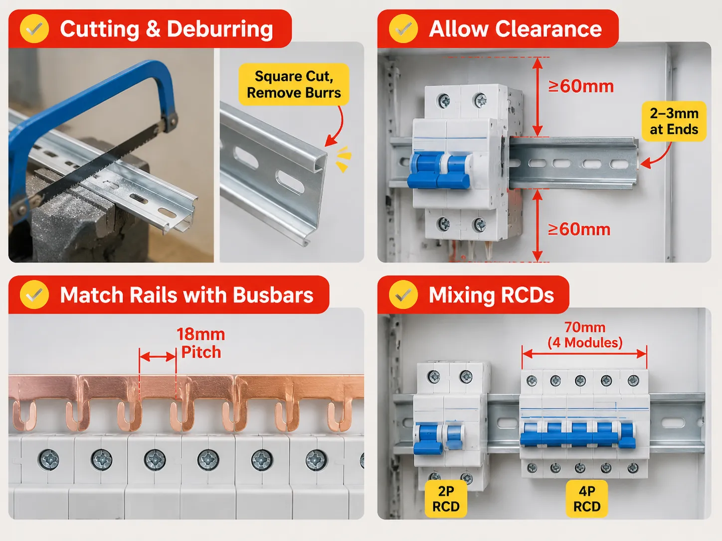
Rails and Enclosures Must Be Matched with Busbars
Devices are positioned on the rails and connected by comb busbars. The busbars have fixed 18mm pitch positions, which consists of 17.5mm module plus the clearance. Care must be taken when working with mixed rows as the busbars with an 18mm pitch will not align with devices that each have an 18mm width because of each having slightly different seating positions. The busbars will not span 2-module RCBOs properly; a gap will occur. A module row should first be designed using modules, and then designed using devices in the same manner that it will eventually be used. This allows for more flexibility when ordering busbar, as it will be ordered according to how many of each type of device it needs, rather than how many busbars can fit into the enclosure.
When a row has both two-pole and four-pole residual devices located in the same row, the pitch mechanics change again. The range of residual current devices can differ significantly in the number of modules included between designs. For example, a four-pole RCCB for a three-phase panel board requires 70 mm. This equates to four circuits that cannot be used for outgoing circuits.
How HUYU Connects
Our modular devices are created with a 17.5 mm module and a 35 mm rail interface, thus determining whether a panel board can be built from the use of multiple brands without needing to rework them. The EXB3 series provides full coverage for B, C and D curve ratings of 6, 8, 10, 15, 20, 25, 32, 40, 50, 63 amp ratings at 6 kA, in single, double, triple and quadruple pole configurations, using the same clip geometry across the range, allowing rows of the devices to be installed without shimming.
By comparison, the EXM3 moulded case breaker can provide service from 16 amp to 250 amp ratings and is an entirely different mounting class; this device is installed by mounting to a plate, instead of clipping on to a rail. It is prudent to understand this difference when a panel board is being drawn, as it is an appropriate assumption that all devices will be modular; this transition typically occurs around 125 amps, which is where the panel board stops becoming a Consumer Unit and becomes a Switchboard. When we make an inquiry about a board, we are asking for three things: The module count, pole configuration, and enclosure width. These three values determine rail, busbar and way counts respectively; if they are not provided with your request, your quotation will reflect only the cost of a product and not the board itself.
Часто задаваемые вопросы
What is the standard size of a DIN Rail?
The DIN Rail is defined as 35mm wide, using a top-hat profile as per IEC/EN 60715, with a height of either 7.5mm (used in conjunction with MCBs or modular devices) or 15mm (used in conjunction with heavier terminal blocks or industrial equipment). Other widths exist. Specifically, 15mm and 75mm, but neither of these is used in conjunction with MCBs.
What is DIN Rail for MCB?
The DIN Rail is the metal channel that the MCB clips onto when placed inside an enclosure. It is the clip that is located on the back side of the MCB that hooks under the front lip of the DIN Rail and snaps over the rear side of the DIN Rail, allowing for the fitting and removal of the MCB without using any kind of tool after isolating the supply.
How wide are DIN Rail circuit breakers by pole?
The width of a single pole DIN Rail circuit breaker is 17.5 mm which equals one module. A double pole circuit breaker will be 35 mm, a three-pole circuit breaker will be 52.5 mm and a four-pole circuit breaker will be 70 mm. A single-module RCBO will be the same 17.5 mm as for the other types of circuit breakers. A two-module version will be 35 mm.
How do you size a DIN Rail?
To determine the size of a CMX enclosure, you multiply the number of modules required by 17.5 mm; this calculation gives you the total usable height of your enclosure. You add an additional 10-15% to the base of the board to allow for future circuits. The height of the usable rail on a 12-way CMX is approximately 210 mm when the enclosure is approximately 250 mm wide.
Is DIN rail used in the same way in all countries?
Approximately 35 mm of usable DIN rail is the standard throughout most of the world according to IEC 60715. The main differences between countries are historical – North America’s residential load centre designs use a proprietary stab-on busbar system which does not use DIN rail, whereas older versions of American and British panel boards were designed to work with a 32 mm G-rail. Older British Panel Boards utilised a British G-rail, while the newer styles now require an adaptator in order to be used with a new style of device.
Is it possible to fit a device with a 15 mm raised profile onto a 7.5 mm base?
Typically not in a secure manner. The device is not designed to fit onto a shallow mount, and the mounting clips on the deeper mount will allow more travel than the shallow mount will accommodate; thus, the device sits loosely and can easily be removed from the rail by a cable pull. To ensure a secure fit, always match the mounted device to the mount profile, or replace the mount.
Ссылки
- Siemens, Modular Devices and DIN Rail Mounting
- ABB, Modular Devices and associated rail kits for mounting according to DIN standard
- Hager, Consumer Unit Dimensions
- Phoenix Contact, manufacturer of DIN Rail Modular Device and Terminal Block Systems
- Electrical Engineering Portal, Design Layout of Panelboards and Modular Devices
Заключение
To sum up, the number 35 mm has been used as a standard mount for CMX enclosures for 35 years. The only differences between the installation/usage is the height of the mounts between installed CMX boards (7.5 mm and 15 mm). In essence, you simply change the physical mounting to install this type of device in an older style of panelboard.