
DIN is short for Deutsche Industrie Norm. DIN 46277 defines the Profile of a Top Hat Rail as being symmetrical so that electrical devices can be mounted easily without worrying about how far from each edge you have to align the device. The original Standard has been Harmonised into EN 50022 then IEC 60715 with regard to the Reference Standard.
The 35 mm Rail Size became the most used and popular rail size because the 35 mm rail width provided a stable clip to secure the Tompson connection and it allowed for Uniformity across the ranges of circuit breakers whilst keeping them compact – the actual width of a 12 way board with the 35 mm rail is approximately 210 mm in width, this format fits into an enclosure that would be approximately 250 mm wide, anything wider than this would waste valuable enclosure space whereas anything narrower than this would not securely hold a device rated at 63 A when the terminal torque is applied.
Other rail widths that can be found are 15 mm, which were historically used for miniature terminal blocks that are still used in control panels today. The 75 mm rail is meant for heavy industrial equipment and for large terminal assemblies. Circuit breakers and other devices do not relate to one another in any way, but both items were included in the same catalogue, which created confusion.
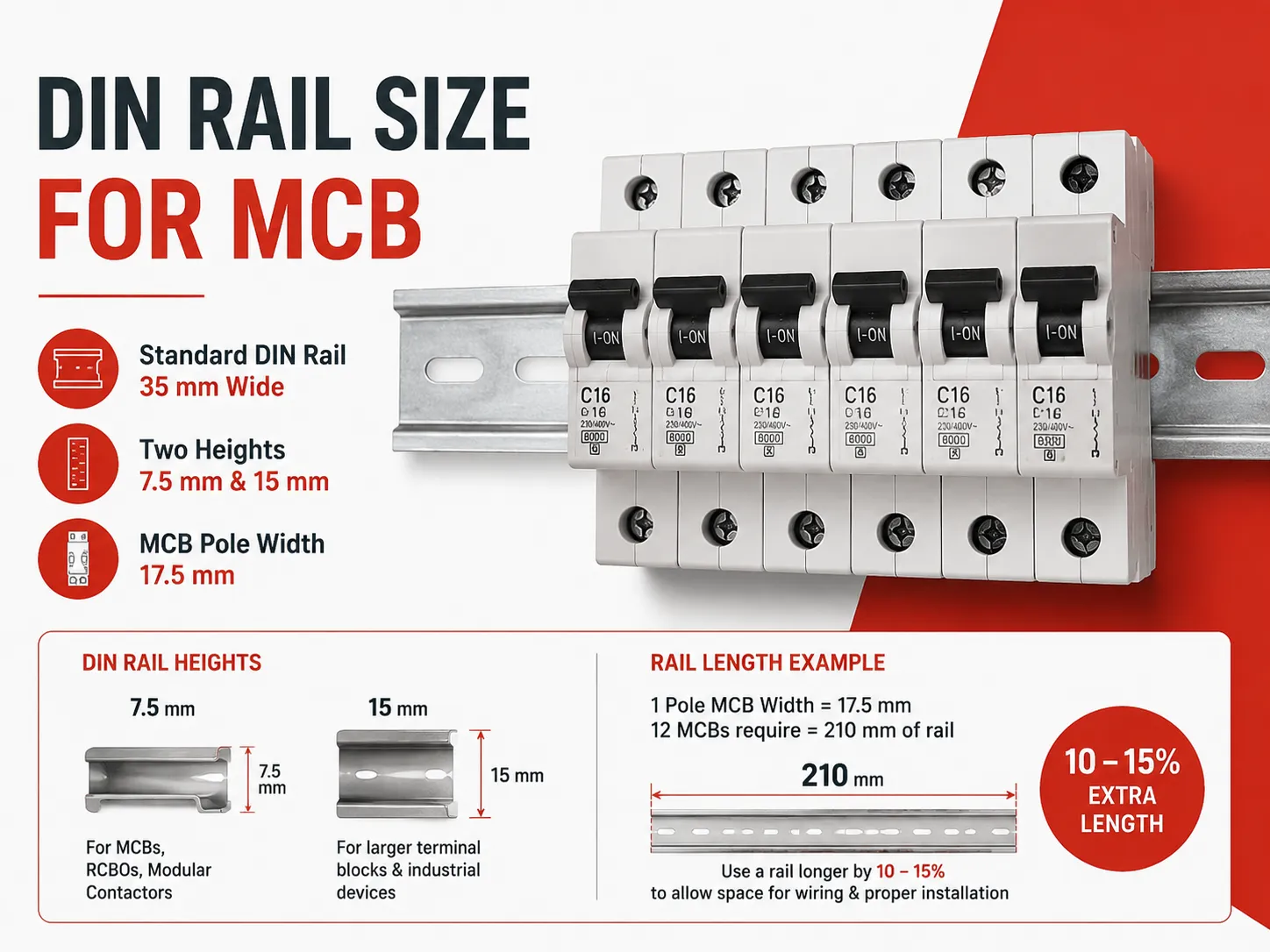
Quick answer: Every MCB attaches to a 35 mm wide rail as outlined by IEC/EN 60715. This profile comes in two different heights – 7.5 mm and 15 mm. The smaller version (7.5 mm) is used for MCBs, Residual Current Circuit Breakers (RCBOs), and modular contactors. The larger version (15 mm) provides added strength to larger terminal blocks and industrial devices. The width of one pole of an MCB is 17.5 mm, so a board containing twelve MCBs requires 210 mm of rail to mount them this means the rail used needs to be larger by 10 to 15 percent to accommodate mounting the MCBs without obstructing wires from connecting to them properly.
What IEC 60715 Specifies
IEC 60715 outlines the size, thickness and tolerances of a rail. Because of this standard, a rail made by one manufacturer is compatible with devices made by another manufacturer. The only dimensions that an installer cares about when using a rail are the rail’s width (35 mm), profile height (7.5 mm or 15 mm) and thickness (for the 7.5 mm profile it is normally 1 mm thick made of cold rolled steel).
The clip located at the back of a device is designed to be spring loaded and will secure itself under the front lip of the rail and then snap over the back edge of the rail. The travel distance of the clip is important, as only devices made for use with a profile height of 7.5 mm can be clipped onto a rail with a profile height of 15 mm as long as they have enough travel. Conversely, a device designed to be used with a 15 mm profile will fit poorly on a 7.5 mm profile rail. Incorrectly mixing both of these types of devices in the same enclosure is a common reason for electronic devices to appear at an angle to their intended position.
Standardisation of the device side portion of the interface also exists with DIN 43880. This standard sets forth the overall dimensions of modular electronic devices. A modular device is defined as having a height of 80 mm for a complete module. A modular device can also be defined as a half module, in other words, 45 mm. The width grid of modular devices, as specified in the DIN 43880 standard, is also defined as 17.5 mm. Therefore, an EXB3 miniature circuit breaker having a current rating of 6 to 63 A occupies exactly one module, and since DIN 43880 provides standardisation of rail mount devices, will also be able to attach to the same rail as either a terminal block or timer relay manufactured by another manufacturer.
7.5 mm vs 15 mm: What Profile Should You Choose?
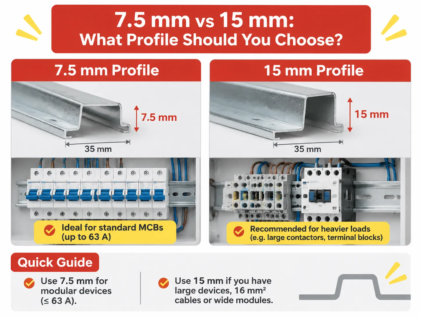
7.5 mm profile is used as a standard across all consumer units and distribution boards due to its thinness, low price and strength to hold multiple circuit breakers; the enclosure supports both ends of the rail, usually with an additional support in the middle.
The 15 mm profile is an upscaled version of the top hat style profile, with the same 35 mm width as the 7.5 mm profile, used where the weight on the rail is heavier than that of circuit breakers, for example, there may be rows of heavy terminal blocks, larger contactors, group starters, or apparatus used continuously (i.e., on and off again). The extra thickness of this profile enables it to withstand the twisting loads, which could otherwise cause problems.
A practical rule for a panel maker; if a row only has modular devices that are rated at up to 63 A, then the 7.5 mm profile will be okay; however, if that row has terminal blocks with 16 mm² cables, or has equipment that is wider than 4 modules, then a 15 mm profile should be used. In cases where there are mixed modules, the device that has the largest clip will be the deciding factor as to which profile will work best for the group; however, the other modules are most likely still compatible with the larger design.
| Device | Poles | Width | Modules |
|---|---|---|---|
| Single pole Miniature Circuit Breaker (MCB) | 1 Pole | 17.5 mm | 1 Module |
| Miniature Circuit Breaker with switched neutral | 1 Pole + Neutral | 35 mm | 2 Modules |
| Double pole Miniature Circuit Breaker | 2 Poles | 35 mm | 2 Modules |
| Three pole Miniature Circuit Breaker | 3 Poles | 52.5 mm | 3 Modules |
| Four pole Miniature Circuit Breaker | 4 Poles | 70 mm | 4 Modules |
| Residual Current Circuit Breaker (RCBO) single module | 1 Pole + Neutral | 17.5 – 18 mm | 1 Module |
| Residual Current Circuit Breaker (RCBO) two modules | 1 Pole + Neutral | 35 mm | 2 Modules |
| Residual Current Circuit Breaker (RCCB)(2P, 4P) | 2 Poles or 4 poles | 35 mm or 70 mm | 2 Modules or 4 Modules |
Both rows below warrant caveats. The single module RCBO is a very useful product because it puts residual and overcurrent protection into the space of one Miniature Circuit Breaker. Because of this, a consumer unit today can fit in eight RCBOs at a width of 140 mm, versus the previous eight RCBOs plus the main RCCB at a width of 210 mm; the two module version is much more common in older designs and/or for ratings greater than 32 A, which require the space for their mechanism.
The pole count of devices in this Table is the reason that typically a range of MCBs is identified based on module count above all physically measured size. When a board schedule states “12 way,” it refers to twelve available modules to attach devices to the guide rail, not twelve devices in total. Therefore, should one designer populate all twelve locations with single pole MCBs and then also add a residual current device (RCD), he/she has already filled the entire guide rail of the consumer unit with devices.
Measuring the Rail You Now Have
You can measure a consumer unit guide rail by measuring the three identifiers for rails listed below in under thirty seconds using a rule. Width: measure from the centre of the flat face of the hat to the centre of the opposite flat face; this measurement is normally approximately 35 mm across each flat face of the rail.
The Profile height (standard rail is reading approximately 7.5 mm and on deep version is 15 mm) measures the distance between the flat face of the profile and the underside of the lip. Thickness Profile typically is measured from the steel profile, because the steel is generally thicker than the other profiles which makes it more difficult to measure and will typically not be measurable during use.
If the Width reads 32mm = G Profile, asymmetrical (with sections) Rail used in older American and British Equipment and still available in some industrial panels. Therefore, G-Rail Devices will not fit onto a 35 mm profile. Therefore, if you want to replace a G-rail Device with a Device for a Standard 35 mm Rail you will need to match the G-rail against the Standard 35 mm Rail.
Fourthly, mounting methods are either fixed or clipped to the backplate of a cabinet. The fixed method can be either replaced or extended; however, a clipped method probably cannot, because the support is formed by the cabinet moulding. This will affect if a board can be upgraded in place, or whether the entire unit must be replaced as an entity.
How to Size a Rail for a Board
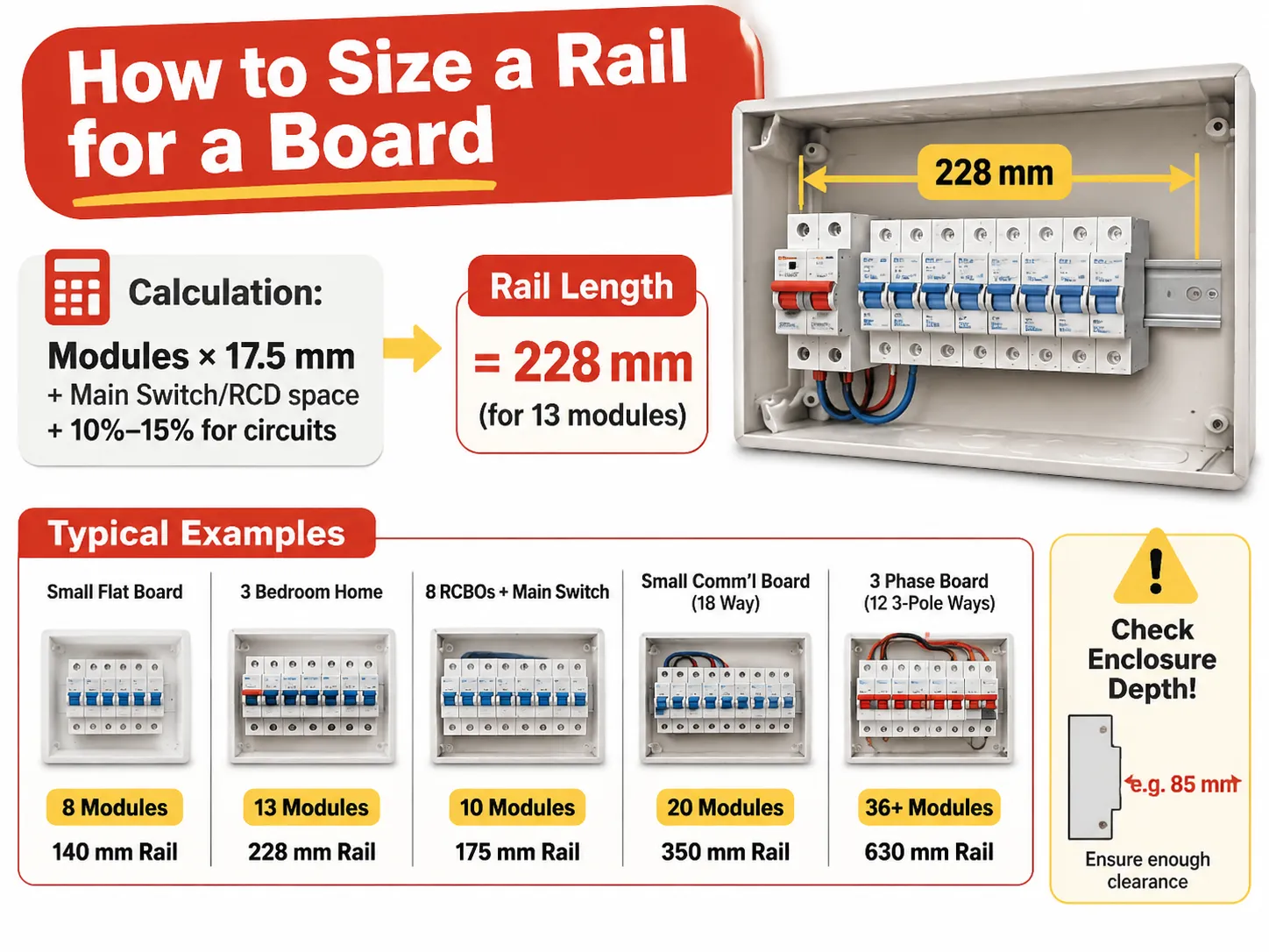
The calculation of how To Size A Rail For A Board, the overall calculations are based on an arithmetic method of Calculating (+ margin) by using the Module count from the Schedule MM and multiplying by 17.5 MM, Adding Main Switch/RCD space If not already counted, and adding add +10%-15% for Circuits which will appear if the board is handed over.
| Board | Modules required | Rail length | Typical enclosure width |
|---|---|---|---|
| Small Flat Board | 8 Modules | 140mm Rail | 200mm Enclosure (8-10 way) |
| 3 Bedroom Home | 1 Main Switch, 10 MCB’s, 13 Modules | 228mm Rail | 250mm Enclosure (12-14 way) |
| House with 8 RCBO’s and a Main Switch | 10 Modules | 175mm Rail | 230mm Enclosure (10-12 way) |
| Small Comm’l Board (18 way) | 20 Modules | 350mm Rail | 400mm Enclosure (18-21 way) |
| 3 Phase Board (12 3-Pole Ways with Main) | 36 or More (plus Main) | 630mm Rail | 700mm Enclosure (2 Rows) |
The enclosure width differs from the rail length, and this creates confusion for people ordering from a catalogue. A “12 way” board has 12 usable module spaces on the rail that are 250mm wide, because the rail is clipped between two end supports, and the enclosure doorframe takes the rest of the space.
Enclosure depth and height determine the space available for installation and do not depend on the enclosure width. For example, with 200 mm’s of usable rail and 100 depths of the enclosure, you will not be able to close the enclosure over an 85mm device projecting from the rail, once the wire is connected. Once the physical dimensions of the electrical box are verified that it is in acceptable limits (height and depth), the electrical box should be checked for clearance against the device’s physical dimensions prior to ordering a board. The ONLY TIME this error occurs is during the actual installation of a board in question.
Does the Rail Vary by Country?
The Rail DO NOT VARY by Country. The 35mm (IEC 60715) rail is widely used throughout the world, so there is no difference between 35mm rail purchased in China (Shanghai) compared to 35mm rail purchased in Western Europe (Rotterdam).
Differences exist on how the equipment will be installed and the differences lead to three separate and distinct areas for the homeowner.
North America has the greatest difference as a North American residential load centre is a proprietary enclosure (fully enclosed) that generally has no DIN Rail at all as the breakers clip directly to the busbar/stab-on type busbars. When DIN Rail appears in Commercial and Industrial work in North America, the standard rail width is 35 mm and in photovoltaic (solar) and Control Panels it is becoming more and more common. Older equipment may have used the 32 mm G-rail.
The British Isles and Ireland have been using the 35 mm DIN rail for many of their more modern Consumer Units; however, many fuse boards from the 1970s and early 1980s used a different mounting method; therefore, an RCBO intended for a fuse board from the 1980s may require an adapter for mounting to a modern Consumer Unit. Australia and New Zealand have been following the IEC standard using 35 mm rail and have developed 17.5 mm wide modules and their breakers are the same as those in Europe. Some Japanese manufacturers are producing breakers and accessories that follow the same basic specifications as European models, and they also use 35 mm rail and JIS tolerances can be compatible for practical application. India, the Middle East, and South East Asia are all fully IEC compliant.
The other major distinction between regions is not with respect to the size of the rail but the size of the actual DEVICE. A single break load centre in North America is approximately 25 mm wide and 1 inch thick per pole, therefore, it has an entirely different dimension form factor; therefore, a panel built for the North American market will not accommodate IEC modular devices, and the decision on rail size will only be made after the project has adopted the IEC system for installation.
Rail Material, Thickness and Why Cheap Rails Fail
The rail is manufactured from Cold Rolled Steel which is Zinc Plated, with a thickness of 1mm for 7.5mm Profile and typically 1.5 to 2mm for deeper profiles. The plating of the rail is important because rail is a conductive path during a fault, and Zinc plated rails will not rust at the mounting holes for approximately 2 years when installed in a moist environment such as plant rooms.
Aluminium rail should not be used for breaker rows. When using an aluminium rail, the aluminium rail will deform under concentrated load when a device’s clip is being removed by way of lever action. Once an aluminium rail has been deformed, the devices will no longer fit square in the rail and also the busbar comb will not align properly. Thus, if an aluminium rail is used, it will be necessary to remove and dispose of the entire rail and all of the devices in order to rebuild the row.
THICKNESS of rail is also a point of failure. RAIL that is 0.6mm thick will flex due to the forces applied from the installation of the devices. This flex will cause the clips to be raised slightly when the devices are installed, causing the devices to appear seated when in fact they are not. This is particularly significant in 36-module, three-phase rows, which is the reason that deep profile rails are manufactured for applications requiring long lengths of rail.
Cutting, Mounting and Clearance
Rails are available in lengths of one meter and two meters. Rails may be cut at the installation site using a hacksaw or a angle grinder. The two most important criteria for ensuring a good cut are to ensure that the rail is cut square along its length and to ensure that both ends of the newly cut section of rail are deburred.A burr on the lip of that device will stop it from clipping onto the rail and lead to a natural reaction of forcing it in place, which in turn causes the rail to bend.
It is important to allow for end stops to have a clearance of approximately 2-3mm at either end due to their load-bearing function rather than just being cosmetic. A row of breakers without end stops can slide sideways, and a row of sliding devices will pull the busbar combing off alignment. It is, therefore, normal practice to use an end stop at each end of a rail which carries more than 10 devices, in addition to one located in the middle of the rail.
The clearance for wiring is most often neglected. Devices extend 70-75mm forward from the rail face and, within the device’s enclosure, the cables will need to bend, therefore the board needs to provide 60mm of clear space above the rail for the incoming side, and the same space below. An RCBO subjected to a shallow enclosure will not provide adequate clearance for bending of the cable, resulting in either a cover that will not close or a pinched cable.
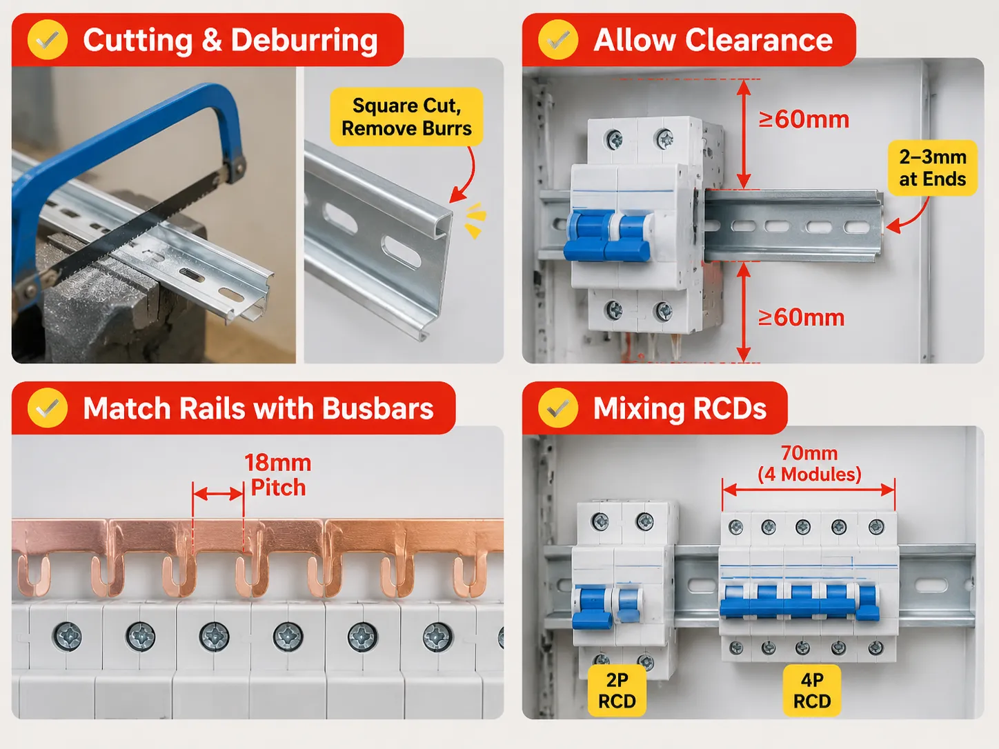
Rails and Enclosures Must Be Matched with Busbars
Devices are positioned on the rails and connected by comb busbars. The busbars have fixed 18mm pitch positions, which consists of 17.5mm module plus the clearance. Care must be taken when working with mixed rows as the busbars with an 18mm pitch will not align with devices that each have an 18mm width because of each having slightly different seating positions. The busbars will not span 2-module RCBOs properly; a gap will occur. A module row should first be designed using modules, and then designed using devices in the same manner that it will eventually be used. This allows for more flexibility when ordering busbar, as it will be ordered according to how many of each type of device it needs, rather than how many busbars can fit into the enclosure.
When a row has both two-pole and four-pole residual devices located in the same row, the pitch mechanics change again. The range of residual current devices can differ significantly in the number of modules included between designs. For example, a four-pole RCCB for a three-phase panel board requires 70 mm. This equates to four circuits that cannot be used for outgoing circuits.
How HUYU Connects
Our modular devices are created with a 17.5 mm module and a 35 mm rail interface, thus determining whether a panel board can be built from the use of multiple brands without needing to rework them. The EXB3 series provides full coverage for B, C and D curve ratings of 6, 8, 10, 15, 20, 25, 32, 40, 50, 63 amp ratings at 6 kA, in single, double, triple and quadruple pole configurations, using the same clip geometry across the range, allowing rows of the devices to be installed without shimming.
By comparison, the EXM3 moulded case breaker can provide service from 16 amp to 250 amp ratings and is an entirely different mounting class; this device is installed by mounting to a plate, instead of clipping on to a rail. It is prudent to understand this difference when a panel board is being drawn, as it is an appropriate assumption that all devices will be modular; this transition typically occurs around 125 amps, which is where the panel board stops becoming a Consumer Unit and becomes a Switchboard. When we make an inquiry about a board, we are asking for three things: The module count, pole configuration, and enclosure width. These three values determine rail, busbar and way counts respectively; if they are not provided with your request, your quotation will reflect only the cost of a product and not the board itself.
Frequently Asked Questions
What is the standard size of a DIN Rail?
The DIN Rail is defined as 35mm wide, using a top-hat profile as per IEC/EN 60715, with a height of either 7.5mm (used in conjunction with MCBs or modular devices) or 15mm (used in conjunction with heavier terminal blocks or industrial equipment). Other widths exist. Specifically, 15mm and 75mm, but neither of these is used in conjunction with MCBs.
What is DIN Rail for MCB?
The DIN Rail is the metal channel that the MCB clips onto when placed inside an enclosure. It is the clip that is located on the back side of the MCB that hooks under the front lip of the DIN Rail and snaps over the rear side of the DIN Rail, allowing for the fitting and removal of the MCB without using any kind of tool after isolating the supply.
How wide are DIN Rail circuit breakers by pole?
The width of a single pole DIN Rail circuit breaker is 17.5 mm which equals one module. A double pole circuit breaker will be 35 mm, a three-pole circuit breaker will be 52.5 mm and a four-pole circuit breaker will be 70 mm. A single-module RCBO will be the same 17.5 mm as for the other types of circuit breakers. A two-module version will be 35 mm.
How do you size a DIN Rail?
To determine the size of a CMX enclosure, you multiply the number of modules required by 17.5 mm; this calculation gives you the total usable height of your enclosure. You add an additional 10-15% to the base of the board to allow for future circuits. The height of the usable rail on a 12-way CMX is approximately 210 mm when the enclosure is approximately 250 mm wide.
Is DIN rail used in the same way in all countries?
Approximately 35 mm of usable DIN rail is the standard throughout most of the world according to IEC 60715. The main differences between countries are historical – North America’s residential load centre designs use a proprietary stab-on busbar system which does not use DIN rail, whereas older versions of American and British panel boards were designed to work with a 32 mm G-rail. Older British Panel Boards utilised a British G-rail, while the newer styles now require an adaptator in order to be used with a new style of device.
Is it possible to fit a device with a 15 mm raised profile onto a 7.5 mm base?
Typically not in a secure manner. The device is not designed to fit onto a shallow mount, and the mounting clips on the deeper mount will allow more travel than the shallow mount will accommodate; thus, the device sits loosely and can easily be removed from the rail by a cable pull. To ensure a secure fit, always match the mounted device to the mount profile, or replace the mount.
References
- Siemens, Modular Devices and DIN Rail Mounting
- ABB, Modular Devices and associated rail kits for mounting according to DIN standard
- Hager, Consumer Unit Dimensions
- Phoenix Contact, manufacturer of DIN Rail Modular Device and Terminal Block Systems
- Electrical Engineering Portal, Design Layout of Panelboards and Modular Devices
Conclusion
To sum up, the number 35 mm has been used as a standard mount for CMX enclosures for 35 years. The only differences between the installation/usage is the height of the mounts between installed CMX boards (7.5 mm and 15 mm). In essence, you simply change the physical mounting to install this type of device in an older style of panelboard.