
Thermal Magnetic Circuit Breakers (TM CB) are the most popular type of circuit breakers and almost all of the circuitry used in these devices is commercially available to consumers. However, it is common that most consumers do not understand how a TM CB works, therefore it is important to understand their function prior to purchasing one. The TM CB has two types of trip mechanisms, a “heat” mechanism that reacts to sustained overloads and a “magnetic” mechanism that reacts to short circuit conditions. Differentiating between these two mechanisms will assist the end user with determining the cause of nuisance tripping and/or slow clearing. Therefore, if you are experiencing either nuisance trip or slow clearing issues with your TM CB, consider which trip mechanism is operating.
In short: TM CB uses a bimetallic strip that will bend over time (seconds to minutes) due to sustained overloads and a solenoid that will trip in milliseconds when the current exceeds a multiple of its rating (5 to 10 times for a C curve). The heat mechanism provides inverse-time protection based upon the thermal rating of the cable where the TM CB is installed. The magnetic mechanism adds trip speed to the thermal mechanism when an excessive current causes a trip condition. The TM CB configuration provides a simple mechanical device that will trip when conditions warrant while requiring no auxiliary power supply and only basic adjustments to the trip settings. TM CBs range in price from $2 for miniature devices to $400 for larger molded case devices of 630 A. Electronic trip units provide the same function as TM CB with current-transformer technology; however, they require much higher purchase prices (two to five times), as well as additional features such as adjustable trip settings, metering and control circuits.
This article provides information on how the TM CB functions, the basic symbols used to identify TM CBs, the patterns of trip curves that TM CBs follow, a comparison of TM CB vs Electronic trip units and Magnetic-only devices, an explanation of how and when to use the different trip types of TM CBs as well as the costs of the devices.
What a Thermal Magnetic Circuit Breaker Is
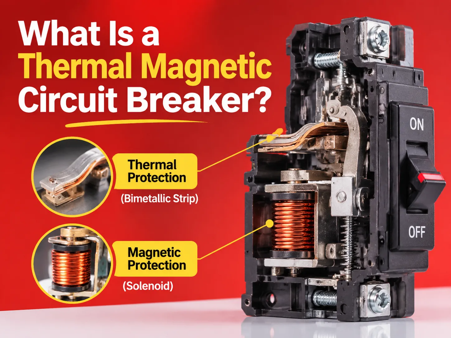
A Thermal Magnetic Circuit Breaker is a circuit breaker that features two different methods of tripping, allowing it to protect against both heat and magnetic overload. The two methods will trip the device independently since they are housed within separate chambers and operate off of the same current flowing through the electrical system.
The thermal tripping mechanism consists of a bimetallic strip, which is comprised of two different metals that are bonded together with different thermal expansion properties. When a current passes through the strip, it creates heat, which causes the strip to bend. Once a predetermined degree of bending has occurred, the strip will trip the latch and disconnect the circuit. Since heating takes time, the trip will be delayed, but as the current increases, the trip will occur sooner. This characteristic is known as inverse-time and allows a feed cable to carry overloads without the breaker opening.
The magnetic tripping mechanism uses a solenoid and armature to trip the circuit breaker. Once a predetermined level of current has been reached, the magnetic force of the solenoid will overcome the spring force holding the armature in place, thereby causing the armature to strike the latch and open the circuit breaker. No heating takes place in this mechanism, so the trip will occur almost instantaneously (usually within 20 milliseconds). Therefore, the magnetic mechanism will clear a short circuit before the cable is damaged.
Both mechanisms operate on the same latch, so the device can be tested as one unit and the trip curve will show two distinct lines.
Working Principle: one element per application, two elements/models = thermal + magnetic
Thermal elements model cable insulation and can only carry so much overload before permanent damage occurs. Bimetal strips are calibrated to trip just below the point of damage to protect the cable and not the appliance.
Therefore, thermal elements will intentionally have slow workings so that breakers provide protection without tripping unnecessarily. i.e. A 32 A breaker carrying 40 A (especially on start-up) may take several minutes to trip – this is correct behaviour since cables rated at 32 A can sustain 40 A for that amount of time before melting insulation occurs.
The magnetic element is designed specifically for the fault/explosion situation that occurs in a fraction of a second and has no intentional delay. The magnetic trip threshold is a multiple of the rated current and this is why, when a magnetic trip device is chosen for motor application, it is important to look at the curve letter rather than the DC rating.
Most application issues arise in the overlap of thermal and magnetic trip conditions. A fault current that is just barely above the magnetic trip threshold could be cleared by either thermal or magnetic element depending on temperature and if the breaker has already been carrying a load or not (i.e. if the thermal element has been heated to a greater extent than if it was cold).When you observe how a trip device performs at 1.3 times its rated load, it is hard to derive repeatable nuisance trip results (i.e., situations where the trip occurs without an apparent reason). However, this phenomenon can be better understood by looking at the reading of the circuit breaker symbols on electrical schematic drawings.
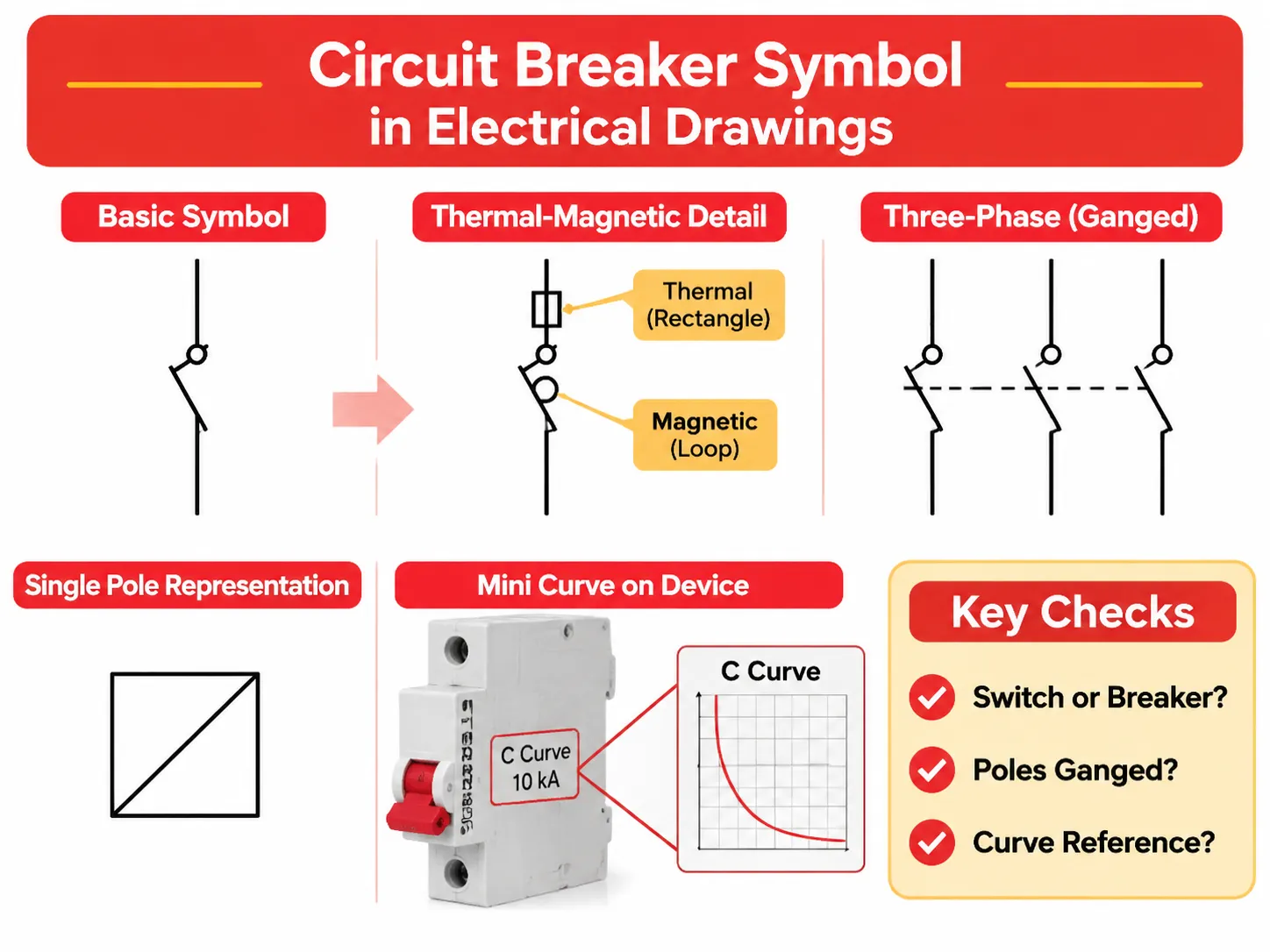
The Symbol and How to Read It on a Drawing
In electrical schematic drawings, the standard symbol for a circuit breaker is represented by a switch contact with a very small square or semicircle at the point of operation. The thermal magnetics version of a circuit breaker will add additional markings for each of those components. The thermal component appears as a tiny rectangle or a C shape in accordance with the International Electrotechnical Commission 60617 Standards, while the magnetic component appears as a very small loop or half-circle (both components are located on the same pole).
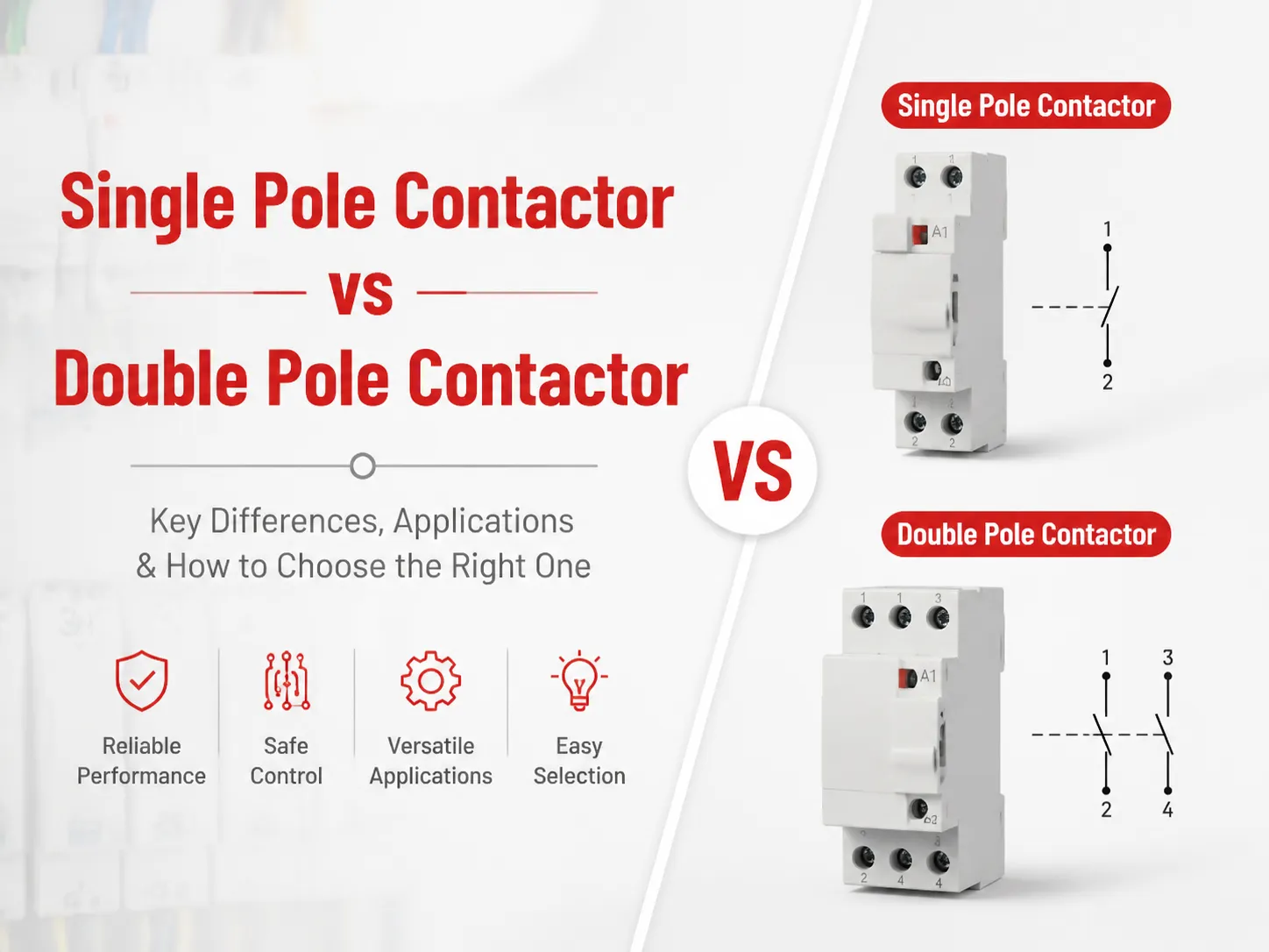
Three things are critical to check when reviewing the schematic of a circuit breaker: is the symbol a switching or breaker/disconnect switch? The switch and breaker disconnect switches look very much the same, but only one of those device types provides for automatic protection. The second critical piece of information that is essential to check is whether or not the poles (that operate the breaker) are ganged together.
In a three-phase circuit breaker, it is critical that all poles of operation open simultaneously (the ganged pole should be depicted with a dashed line linking the pole mechanisms together). The third critical piece of information that must be reviewed is whether or not the circuit breaker symbol has a curve reference associated with it. A breaker symbol without an accompanying curve has not given any specification about the device.
The representation of a breaker in a single pole representation, including the breaker thermal magnetic detail, is generally greatly simplified to a square with a diagonal line drawn across it, or to a rectangular shape with a line drawn across it. As illustrated in the single line drawing, the thermal magnetic symbol is not depicted, which provides adequate information for layout purposes. When conducting a protection study, however, the protection study requires a curve and settings and does not require a symbolic representation of the breaker.
Rather than a drawing, manufacturers also print a mini curve on the side of the device. The mini curve is much more relevant to the device as it relates specifically to that device. If a device has a rating (on its mini curve) of a C curve rating and a10 kA interrupting capacity rating, that is all the information required to make a selection, as long as the fault level on that device is below 10 kA.
Trip Curve: B, C, D and What the Numbers Mean
The four trip curves, B, C, D, and their corresponding numbers, indicate a magnetic trip range as a multiple of the rated current. The letter associated with the trip curve is the most important piece of information to determine which miniature circuit breaker to use.
| Curve | Magnetic Trip Range | Typical Application | Tolerable Load |
|---|---|---|---|
| B | 3-5 x rated current | resistive loads, long runs, lighting | Little or no inrush. Strong push toward quick trip clearing. |
| C | 5-10 x rated current | general purpose, mixed loads, small motors | Moderate inrush. |
| D | 10-20 x rated current | transformers, motors, welders, pumps | Large inrush with no nuisance tripping. |
| K | 10-14 times, thermal 1-2 | High-start current motors | Continuous overload close to rating. |
| Z | 2-3 x rated current | electronics, semiconductor protection | Very sensitive with no inrush. |
Each curve contains two areas. The thermal area of each curve covers a range of currents for a device = from 1.13 to 1.45 times its rated current. The device must not trip at 1.13 times its rated current and must always trip within 1 hr at 1.45 times its rated current, as per the requirements in IEC 60898-1.The threshold at which the magnetic region starts is the curve’s straight vertical point on the graph; thus, trip times for the electrical use remain less than 20 milliseconds, no matter how far out the electrical service is above that threshold.
Between these two areas is a transition band in which the trip device may get their electrical service or not. Choosing a trip curve is to be more about where to set that transition band with respect to the initial impulse seen by the load being protected.
For example, a pump that requires eight times its nameplate rated current (8x) for an initial impulse (i.e. for a period of ½ second), needs a trip curve that has a magnetic threshold setting of greater than 8x, such as for curves D or K, rather than curve C.
The trip curve will also determine the maximum length of the cable run that can be protected by the circuit breaker. Long cable runs experience sufficient impedance to cause the fault current at the far end of the cable run to be reduced; consequently, if the reduced long run fault current falls below the trip curve’s magnetic threshold, the circuit breaker will not trip immediately. This is why most long-length lighting circuits use B trip curves, which can trip at a lower factor of multiple to keep the far ends of the cables in reach.
Thermal Magnetic Breakers vs Electronic Trip Units
While electronic trip units are an option to use in place of thermal magnetic circuit breakers (MCB), the big difference is that electronic trip units have the ability to do much more than thermal magnetic circuit breakers do.
An electronic trip unit measures its incoming electrical service with internal current transformers, digitises (converts) the waveform of that incoming electrical service, and determines when to trip via computer (computer program software). The use of an electronic trip unit gives the user the flexibility to select a long time setting (I), a short time setting (Im), a short time delay (tsd), and a ground fault element (on larger electronic trip units, there can also be the ability to monitor and communicate).
A thermal magnetic circuit breaker is not adjustable as confirmed by the following table:
Thermal Magnetic Circuit Breaker vs. Electronic Circuit Breaker
| Adjustability | Fixed Curve | Adjustable: Ir, Im, tsd, Ground Fault |
| Accuracy | ±10%-20% | Accurate to ±5% or Better |
| Auxiliary Supply | None | Self-Powered by Circuit in Most Designs |
| Metering/Communication | None | Current/Voltage/Energy, Modbus/Ethernet |
| Trip Behavior When Hot | Early Trip and Derating Apply | Temperature Compensated |
| Price of 250A | $120-$400 | $300-$800 |
When comparing thermal magnetic and electronic circuit breakers, the thermal magnetic circuits have several distinct advantages:
- No power source is required for thermal magnetic devices to operate. They are able to function even when the electrical circuit is dead.
- There are no electronic components in thermal magnetic devices, so they have a much lower chance of failure in high heat or high harmonic environments.
- The price difference between thermal magnetic and electronic circuit breakers is significant. In fact, the price of thermal magnetic devices is typically a third of the price of electronic devices, which is important for applications requiring many devices. In some cases there may be as many as 40 or more outgoing cables from one main circuit breaker.
Electronic circuit breakers are useful for applications requiring engineered selectivity. An example would be a short time delay that enables a main breaker to provide time for a feeder breaker to clear a fault before tripping. This is how a plant can avoid losing an entire switchboard due to a single motor failure.
The ability to engineer selectivity into a circuit breaker is an inherent capability of electronic devices and is why they are typically used as main incomers, while thermal magnetic breakers are used for feeder applications. In applications that do not require selective options, there are lower cost options, such as molded case breakers with adjustable thermal magnetic trip settings. They provide the same functionality as electronic circuit breakers at significantly lower costs.
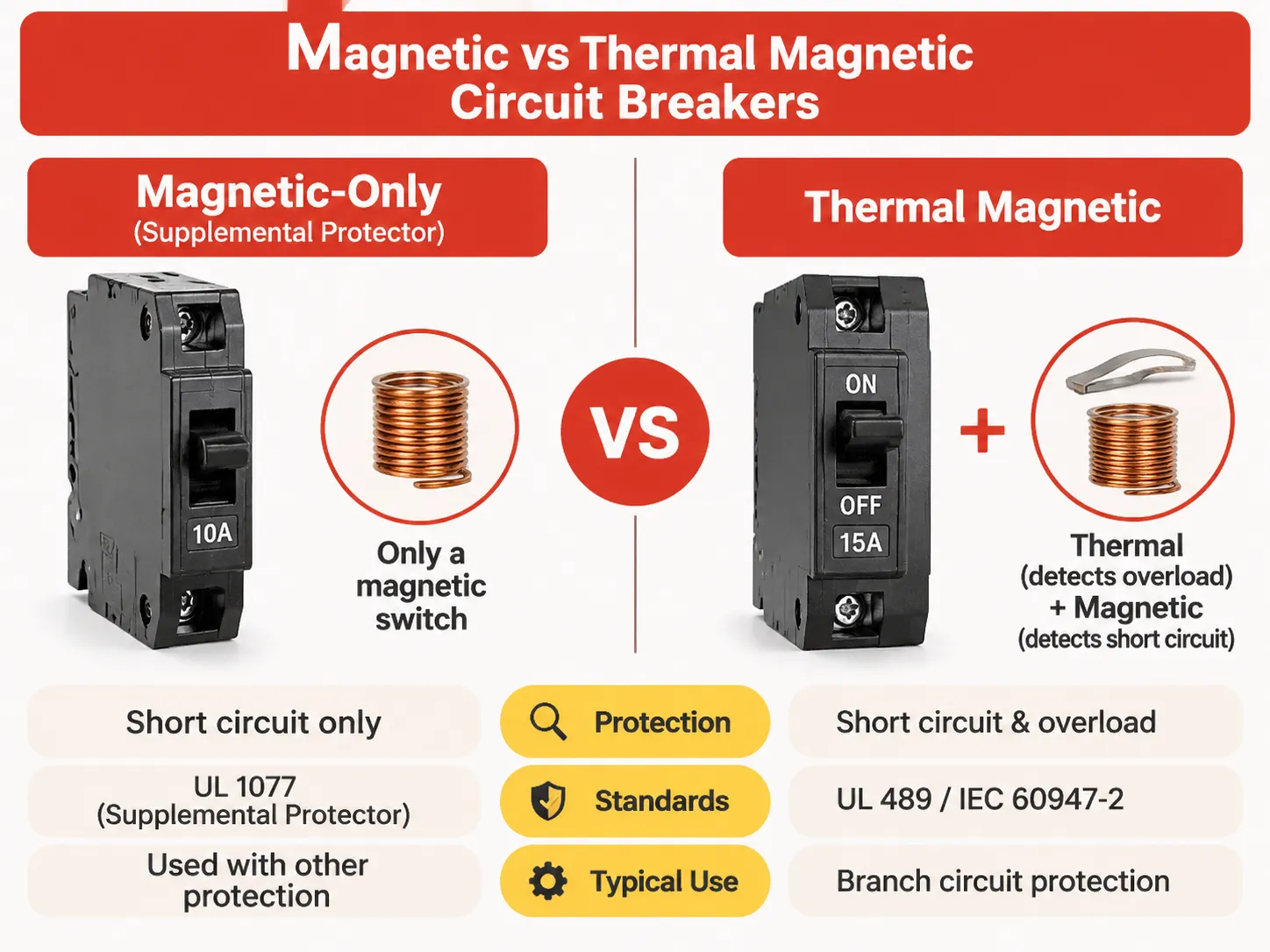
What’s the Difference Between Magnetic and Thermal Magnetic Circuit Breakers?
An electric circuit protector (also known as a “breaker”) that is magnetic-only is basically made up of just the electromagnetic switch (solenoid) and nothing else. It can only detect short circuit faults; thus, it cannot detect overloading conditions so it is used as a supplemental protector.
The difference between these two types of electric circuit protection units is regulatory rather than technical. The UL 1077 standard for North America defines the magnetic-only circuit protectors as “supplemental protectors” which can be used as part of a branch circuit protection system, but are not permitted to be used as branch circuit protection devices as they have not been tested for overloads.
Devices that comply with either UL 489 or IEC 60947-2 standards contain both components (a magnetic switch and an overload detection mechanism) and are permitted to be used as branch circuit protection devices. While the actual size and shape of each type of device is very close, there are huge legal and regulatory differences between the two.
Magnetic-only circuit protectors are used where an overload protection mechanism exists elsewhere, like equipment that has its own thermal protection or in the semiconductor circuit where rapid discharge of current is desired, or in some applications where constant DC current is used. A typical household distribution panel does not fall into any of those categories, and thus, if a magnetic-only device was used to protect a distribution panel, it would leave the conductor carrying the load unprotected from overheating due to overload conditions.
There is a great deal of confusion in the marketplace regarding the term “magnetic breaker.” Many people use this term to reference any type of breaker using a magnetic element; this includes every thermal magnetic type of breaker. This practice is common in sales literature, which makes it much more difficult for specification reviewers to differentiate between products with different types of certification using the same terminology.
Thermal Magnetic Circuit Breaker vs Molded Case Circuit Breaker
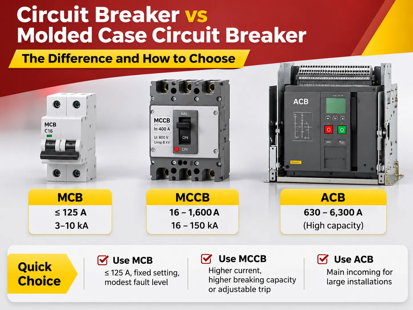
Although it may appear that the comparison between thermal magnetic circuit breakers and molded case circuit breakers are opposites, they are not, and the reason this comparison is made in search results is due to the fact that people searching are assuming that they are.
Essentially, an MCCB is a case projected to have the same maximum rating as its housing; however, the electrical rating of the circuit breaker is defined according to its inherent trip technology. Therefore, it can be either ‘thermal magnetic’ or ‘electronic’, and both types are quite widely used.
For example, a 250 A Molded Case Breaker (‘MCCB’) with a thermal magnetic trip unit would also meet the definitional requirements of a Molded Case Circuit Breaker (‘MCCB’). The same frame type with an electronic trip unit will not be thermal magnetic, yet will still be classified as a ‘MCCB’.
In practice, it is important for a specification to describe both of these characteristics, namely the frame type and the trip technology. A schedule that indicates a ‘250 A MCCB’ describes the frame type, but does not provide any information relating to the protection provided. This means that two different suppliers may be able to quote a specified line in their schedules using devices with very different behaviours.
The behaviour comparison between MCCBs and mini circuit breakers covers the same subject matter from differing perspectives, and it is useful to read both reports together because the two types of devices often get combined in project schedules.
Where Each Type Is Used
Thermal magnetic devices are commonly used for final circuit protection and sub-main circuits where load is relatively predictable; the amount of overload can be limited; the fault current is not particularly high; and the load centre contains several circuits, therefore a simple, low cost passive device is the appropriate engineering solution.
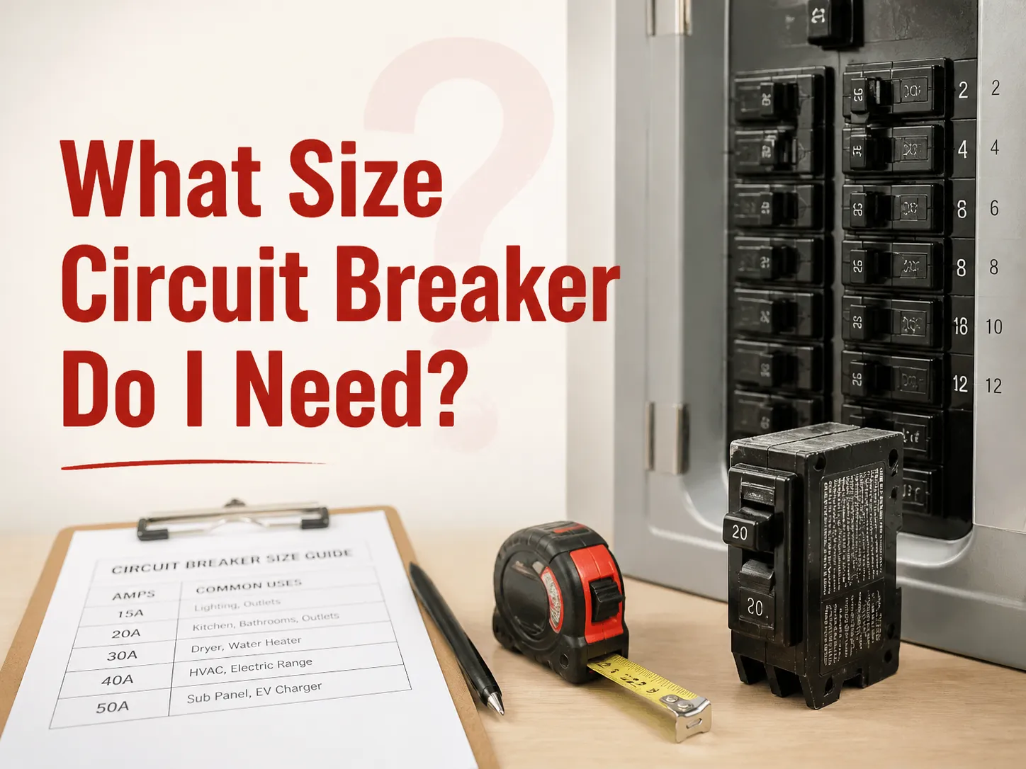
A typical domestic load circuit will have a 63 A main switch and multiple mini circuit breakers with C-curves, all thermal magnetic.
An RCD (Residual Current Device) or RCBO (Residual Current Circuit Breaker with Overcurrent Protection) is added to socket circuits by many commercial switchboards in addition to keeping all other protection by thermal magnetic only. For a Machine Panel there would be a 100 A Molded Case Circuit Breaker with Thermal Magnetic trip due to known starting current of motor and coverage with D curve or adjustable magnetic setting for the motor’s start time.
Electronic trip devices would be used at the main incoming supply of a plant as well as on the feeders that must co-ordinate with devices below them and anywhere there is a requirement for seeing metrics such as energy management purposes. Also found on generators and circuits that will require changing trip settings after the equipment has been commissioned without having to replace the device.
From previous experiences on many projects the normal pattern will use thermal magnetic for all applications below 250 A unless engineered for selectivity, the use of electronic trip for all applications over 400 A, and a mix of each in between 250 A to 400 A. Therefore this pattern is not damning, it explains most switchboards manufactured in the previous ten years. The Molded Case Circuit Breakers used in Distribution Switchboards manufactured have been manufactured in both versions for just that reason.
Within the comparison of devices prices above, the Thermally magnetic type is the least expensive option for all devices; however, the difference between the price step up from the Thermal Magnetic to the Electronic Trip at the 250 amp frame is smaller than the difference at the 630 amplifier frame, which means that typically function will be the main reason to choose one over the other, rather than price. If you are installing a board that has 20 outgoing circuits and you do not require circuit selectivity, there is no reason to use an electronic trip on these circuits.
What It Costs
In addition to device costs, there are two costs that are often overlooked: Commissioning and Spare Parts. For the Thermal Magnetic device, there is no requirement to set the device at commissioning, whereas, for the Electronic Trip device, there will be a commissioning process that requires the setting to be recorded, which will result in additional Engineering costs per device.
The second cost associated with the Spare Parts is the Electronic Trip, which is supplied as a replaceable module and has a different part number and lead time than the Thermal Magnetic device, which is supplied as an entire device assembly. However, some models of the Molded Case Breakers are sold in separate pricing for the frame and for the circuit breaker type due to the fact that the two components of the device are priced based on different cost drivers.
Where HUYU fits
We produce both miniature and molded case thermal magnetic trip circuit breakers with ratings ranging from 1A to 1600A. All of our products comply with IEC standards, specifically IEC 60898-1 and IEC 60947-2, as well as UL 489. The vast majority of our product offerings will be utilized in various applications such as distribution boards, machine control panels, and OEM equipment where customers want to be able to use multiple products from one manufacturer, instead of having to worry about matching higher-end specifications of an individual product.
Our miniature circuit breaker line includes a variety of curve types: B, C, and D curves; and are rated for either 6 kA to 10 kA in an 18 mm wide footprint. Each circuit breaker is marked with the trip curve type and the magnetic threshold is shown, not implied. Additionally, our molded case circuit breaker line includes products rated from 16A to 250A and has multiple settings for each frame to allow for protection of multiple cable sizes.
What HUYU does not claim is that thermal magnetic trip devices provide the same functionality as electronic trip devices. Thermal Magnetic Trip Devices cannot be set to have an Instantaneous delay, nor are they capable of reporting energy consumption. In any circumstance that requires either one of those two features in a project is the correct solution an electronic circuit breaker will be used and we will provide the correct solution rather than quoting a product we ultimately will replace after the first coordination study.
FAQ
What is a thermal magnetic circuit breaker for?
A thermal magnetic circuit breaker is used any time you require both Overcurrent and Short-Circuit protection from a passive device.
In domestic and commercial distribution boards, the final circuits contain thermal and magnetic circuit breakers to provide fault protection and thermal overload protection for the entire branch circuit. Therefore, these types of circuit breakers can protect the electric cable’s thermal capacity as the thermal element protects the electric cable or final circuit before the cable is damaged, while the magnetic element protects the electric cable or final circuit from short-circuit fault conditions.
What is the difference between a magnetic circuit breaker and a thermal/magnetic circuit breaker?
A magnetic circuit breaker is a circuit breaker that has only the solenoid, so it is a short-circuit protection only. Thermal/magnetic circuit breakers are circuit breakers that have both a solenoid and a bimetallic element. Thermal/magnetic circuit breakers can provide both short-circuit protection and sustained overload protection. Magnetic circuit breakers are considered to be supplementary protections and are certified under UL 1077 standards, while thermal/magnetic circuit breakers can be used as a branch circuit protective device because they have been tested for both thermal and magnetic trip functions.
How does a thermal/magnetic circuit breaker work?
Thermal/magnetic circuit breakers work by having a bimetallic strip and a solenoid coil, so that when there is a sustained overload, the bimetallic strip will heat up, causing the strip to bend until it releases the latch. The amount of time it takes to trip the circuit will decrease as the amount of current increases, because the more current there is in the coil, the more magnetic force is developed in the coil, causing an armature to pull the bimetallic strip, which strikes the latch, opening the contacts in less than 20 milliseconds. Both elements act on one mechanism, so that either element can trip the breaker.
What are thermal circuit breakers?
Thermal circuit breakers rely only on the heating effect from the thermal properties of a bimetallic strip. The bimetallic strip is bent due to the current heating it. The temperature rises until it reaches a calibrated temperature, at which point the bimetallic strip releases the latch.
A thermal circuit breaker will provide time/temperature inverse relationship protection that emulates a cable’s thermal capacity, so that a thermal circuit breaker can tolerate a momentary overload but will trip for sustained overload conditions. Because thermal circuit breakers have no magnetic element, they are typically used with an additional device to handle short-circuit fault conditions.
References
- UL Solutions – UL 489 Molded Case Circuit Breakers and UL 1077 Supplementary Protectors
- NEMA – Molded Case Circuit Breaker Application Data
- Hitachi Energy – Low Voltage Protection and Switchgear
- Schneider Electric – Circuit Breaker Trip Curves and Selectivity
- Legrand – Circuit Protection and Distribution Products
Conclusion
A thermal/magnetic circuit breaker is essentially two devices (thermally and magnetically) in one housing. The slow thermal element protects the cable while the fast magnetic element protects the cable from faults. Therefore, when selecting a thermal/magnetic circuit breaker, everything comes from that split. This is why the letter designation of the curve is more important than the current rating for an electric motor circuit.
The terminology traps are very important to understand. A molded case circuit breaker can be either a thermal/magnetic circuit breaker or an electronic circuit breaker, so they do not correlate with one another. A magnetic-only circuit breaker is a supplementary protector, not a branch circuit protective device. Electronic trip units provide adjustability and metering capability, but they do not provide enhanced protection accuracy; therefore, most distribution boards are equipped with thermal/magnetic circuit breakers for each outgoing circuit.