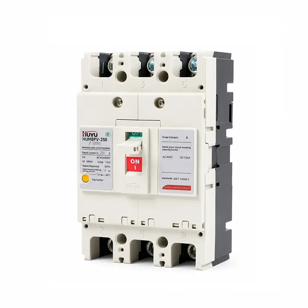
Disjoncteur à Boîtier Moulé Photovoltaïque HUM8PV
La série HUM8PV est un disjoncteur moulé photovoltaïque classé de 16A à 690A à DC 1000V. Fournit une protection contre les surcharges avec un délai long et une protection instantanée contre les courts-circuits. Disponible en 3P et 4P avec plusieurs accessoires (déclencheur à shunt, contacts auxiliaires/d'alarme, mécanisme moteur). Conforme à la norme IEC 60947-2. Pour les systèmes photovoltaïques solaires, les boîtes de combinaison et la distribution DC.
Norme : IEC 60947-2
Courant nominal : 16A – 690A (cadre 125/250/400/630)
Tension nominale : DC 1000V
Pôles : 3P, 4P
Capacité de coupure (Icu/Ics) : Jusqu'à 65kA / 50kA (DC750V)
Applications : Systèmes photovoltaïques solaires, boîtes de combinaison, distribution DC, protection des onduleurs
Détails du produit
Application
Le disjoncteur moulé photovoltaïque HUM8PV (ci-après dénommé disjoncteur) est appliqué au circuit DC avec une tension nominale allant jusqu'à DC1000 V et un courant nominal de 16A à 690A. Doté de fonctions de protection contre les surcharges avec un délai long et de protection instantanée contre les courts-circuits, le produit peut distribuer l'énergie électrique et protéger la ligne et l'équipement contre les dommages dus aux surcharges, aux courts-circuits et à d'autres pannes. Ce produit est conforme à la norme IEC60947-2.
Conditions de fonctionnement normales
Température ambiante : -25°C à +70°C ; température moyenne sur 24h : ≤ +35°C
Altitude : $ ≤ $ 2000m
Humidité : L'humidité relative de l'air sous la température maximale de +40°C ne peut pas dépasser 50% ; sous la température minimale, l'humidité relative est plus élevée, la température moyenne la plus basse du mois le plus humide ne peut pas dépasser +25°C, et l'humidité relative moyenne ne peut pas dépasser 90% ;
Degré de pollution : classe 3
Monté dans des endroits sans risque d'explosion, sans gaz pouvant être corrosifs pour les métaux ou des gaz pouvant endommager l'isolation, et avec peu de poussière conductrice
Catégorie de montage : III
Modèle et signification
Modèle et signification
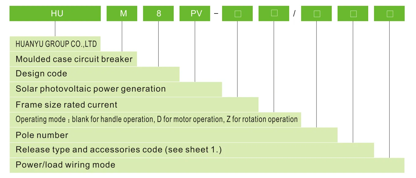
Type de déclencheur et code des accessoires
| Accessoires nom |
Non accessoires |
Alarme contact |
Déclencheur à shunt |
Auxiliaire contact |
Déclencheur à shunt et auxiliaire contact |
Deux groupes de contacts auxiliaires |
Déclencheur à shunt et alarme contact |
Auxiliaire contact et contact d'alarme |
Déclencheur à shunt, contact auxiliaire et contact d'alarme |
Deux groupes des contacts auxiliaires, contact d'alarme |
| Type de déclencheur de surintensité | Code | |||||||||
| Déclencheur instantané | 200 | 208 | 210 | 220 | 240 | 260 | 218 | 228 | 248 | 268 |
| Déclencheur duplex | 300 | 308 | 310 | 320 | 340 | 360 | 318 | 328 | 348 | 368 |
| Remarque : Selon le mode de câblage de l'alimentation/charge, type E, F pour 3P ; type G, H, I pour 4P | ||||||||||
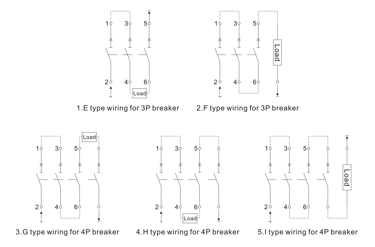
Pour les systèmes d'alimentation selon le mode de câblage ci-dessus, veuillez consulter la feuille 2.
| Système d'isolation à la terre | Système de mise à la terre négative | Système de mise à la terre du point neutre | |
| DC500V | E | E, F | – |
| DC750V | E、H | F、G、I | H |
| DC1000V | H | 1 | H |
Principaux paramètres techniques
| Courant nominal de la taille du cadre | 125 | 250 | 400 | 630 | |||||
| Courant nominal In(A) | €�20、25、32、40、50、63、80、100、125 | €�125、160、180、200、225、250 | €�250、315、350、400 | €�500、630 | |||||
| Nombre de pôles | 3 | 4 | 3 | 4 | 3 | 4 | 3 | 4 | |
| Tension d'isolation nominale Ui(V) | 1000 | ||||||||
| Tension d'impulsion nominale Uimp(V) | 8000 | ||||||||
| Tension de service nominale Ue(V) | DC 500 DC750 |
DC750 DC 1000 |
DC 500 DC750 |
DC750 DC 1000 |
DC 500 DC750 |
DC750 DC 1000 |
DC 500 DC750 |
DC750 DC 1000 |
|
| Catégorie d'utilisation | A | ||||||||
| Limite/service nominal court-circuit capacité de coupure Icu/lcs(kA) |
DC500 | 15/15 | 65/65 | 65/65 | 65/65 | ||||
| DC750 | 5/5 | 15/15 | 40/20 | 50/50 | 40/20 | 50/50 | 40/20 | 50/50 | |
| DC1000 | 5/5 | 40/20 | 40/20 | 40/20 | |||||
| Distance de claquage(mm) | ≤50 | ≤50 | ≤100 | ≤100 | |||||
| Fonctionnement performance (fois) |
Sous tension | 5000 | 5000 | 1000 | 1000 | ||||
| Hors tension | 10000 | 10000 | 5000 | 5000 | |||||
Courbe des caractéristiques de protection
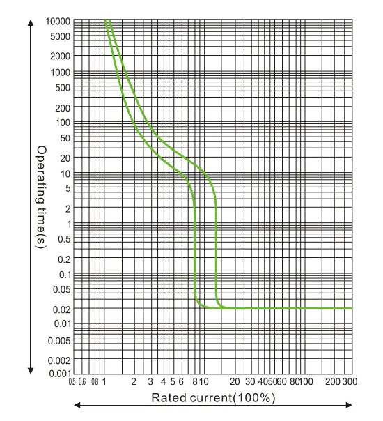
Courbe des caractéristiques de protection en température et courant HUM8PV-125
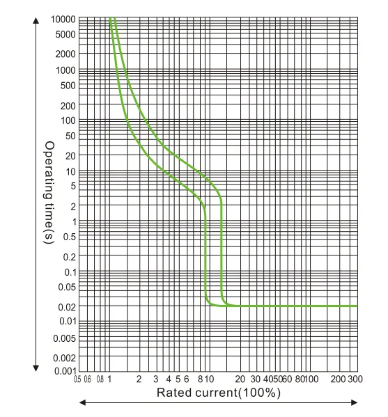
Courbe des caractéristiques de protection en température et courant HUM8PV-250
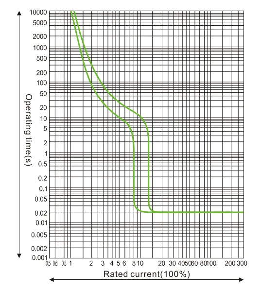
Courbe des caractéristiques de protection en température et courant HUM8PV-400
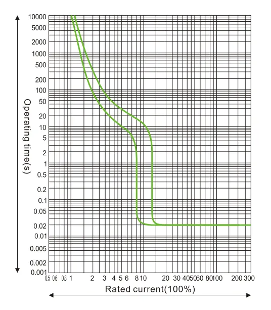
Courbe des caractéristiques de protection en température et courant HUM8PV-690
Coefficient de réduction de capacité en fonction de la température.
| 10℃ | 20℃ | 30℃ | 40℃ | 50℃ | 60℃ | 70℃ | |
| HUM8PV-125 | 15In | 11In | 15In | 1In | 93In | 85In | 8In |
| HUM8PV-250 | 15In | 11In | 15In | 1In | 93In | 85In | 79In |
| HUM8PV-400 | 16ln | 11In | 15In | 1In | 94In | 86ln | 81In |
| HUM8PV-630 | 17In | 11In | 15In | 1In | 9In | 8In | 7In |
Le coefficient de réduction de capacité en haute altitude : lorsque l'altitude dépasse 2000 m, le disjoncteur doit être ajusté selon la feuille 4
| Altitude (m) | 2000 | 3000 | 4000 | 5000 |
| Tension de tenue en fréquence industrielle | 3000 | 2500 | 2000 | 1800 |
| Coefficient d'ajustement du courant de fonctionnement | 1 | 0.94 | 0.88 | 0.83 |
Application en système DC : les aspects suivants doivent être pris en compte avant de choisir un disjoncteur dans un système DC.
a. tension nominale de fonctionnement, en tenant compte du nombre de pôles en cascade
b. courant nominal, en tenant compte de la puissance de charge
c. capacité de coupure, en tenant compte du courant de court-circuit maximal sur le site d'installation
d. mode de mise à la terre, voir feuille 5
| Type de système | Système de mise à la terre | Système sans mise à la terre | ||
| Tous types de défauts | 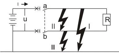 |
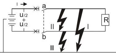 |
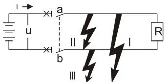 |
|
| Effet de la défaillance | Défaillance I | Génère un courant de court-circuit maximal Contact connecté au pôle positif coupé |
Tension U/2 produisant un courant de court-circuit maximal Contact connecté au pôle négatif coupé |
Aucun effet |
| Défaillance II | Génère un courant de court-circuit maximal Tous les contacts en cascade coupés |
Génère un courant de court-circuit maximal Tous les contacts en cascade coupés |
Génère un courant de court-circuit maximal Tous les contacts en cascade coupés |
|
| Défaillance I | Aucun effet | Identique à la défaillance I Mais uniquement pour le contact connecté au pôle négatif |
Aucun effet | |
| La pire situation | Défaillance I | Défaillance I et Défaillance II | Défaillance II | |
| Situation de coupure | Cascade au pôle positif et coupure simultanée | Pour chaque pôle, coupure du courant de court-circuit maximal à U/2 | Deux pôles coupés simultanément | |
Dimensions générales et de montage
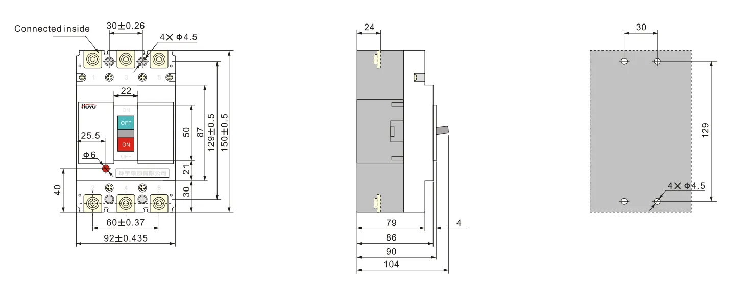
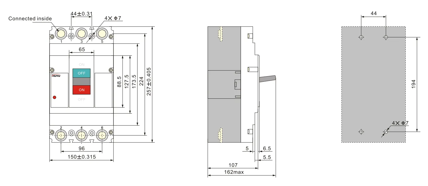
Câblage type E pour 3P HUM8PV-125 (connexion avant)
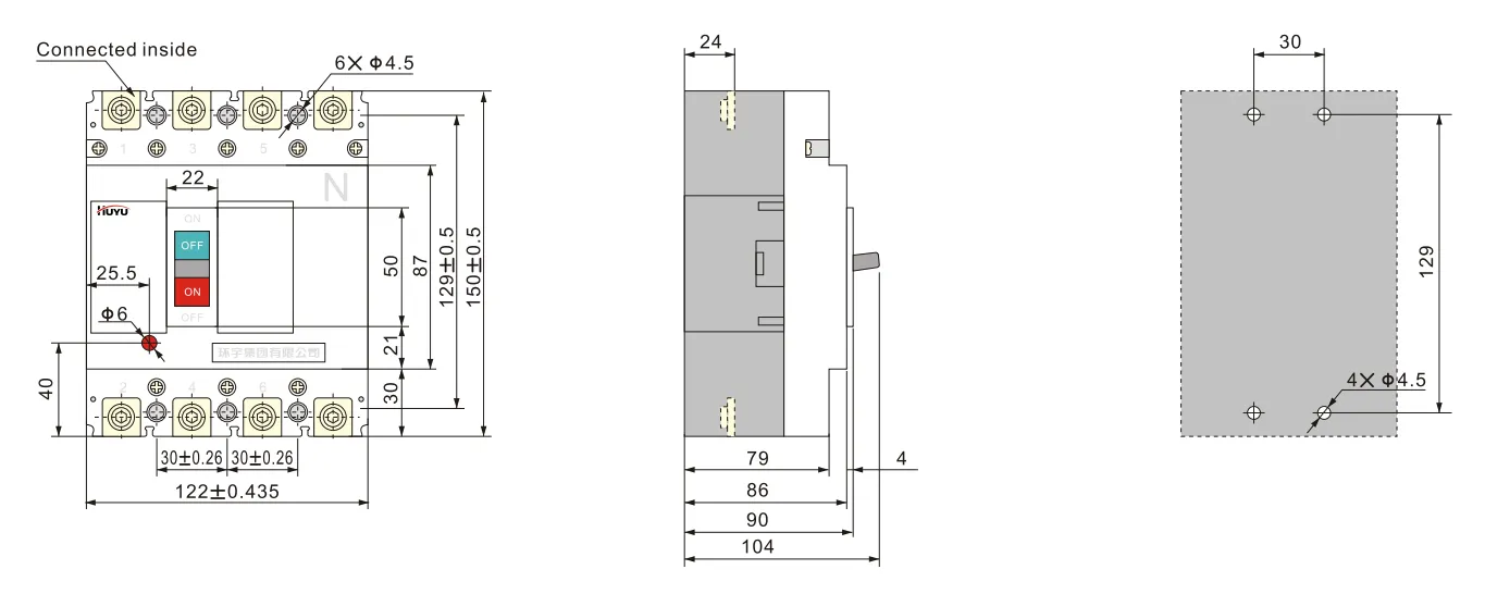
Câblage type H pour 4P HUM8PV-125 (connexion avant)
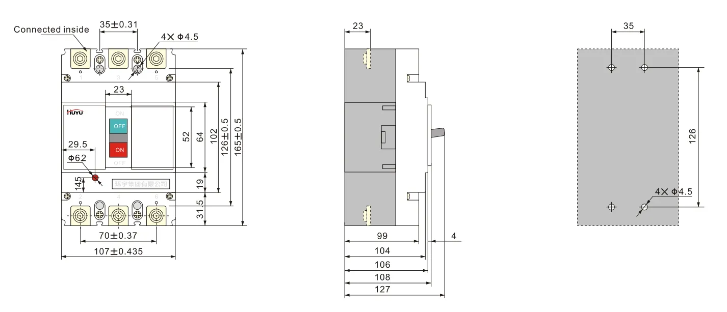
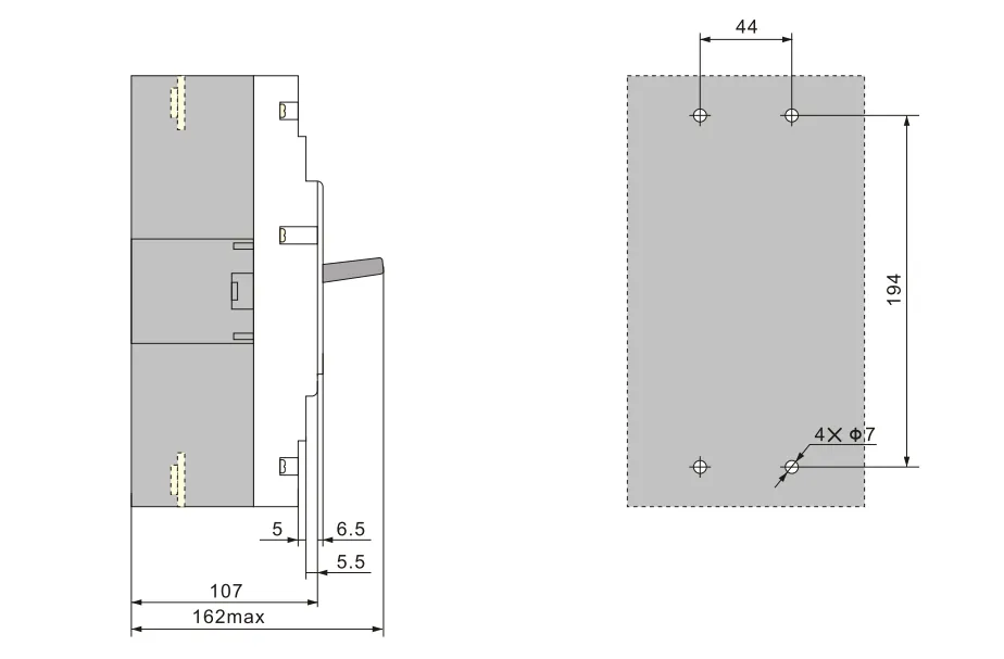
Câblage type E pour 3P HUM8PV-250 (connexion avant)
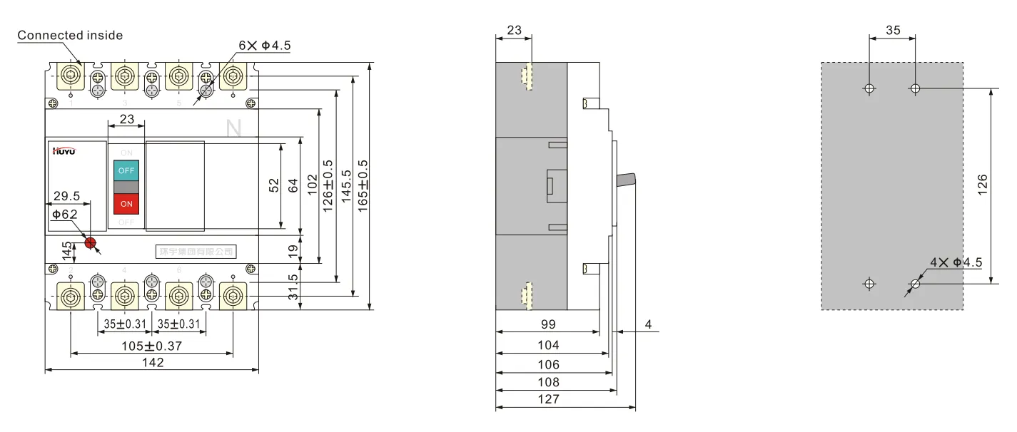
Câblage type H pour 4P HUM8PV-250 (connexion avant)
Câblage type E pour 3P HUM8PV-400 (connexion avant)
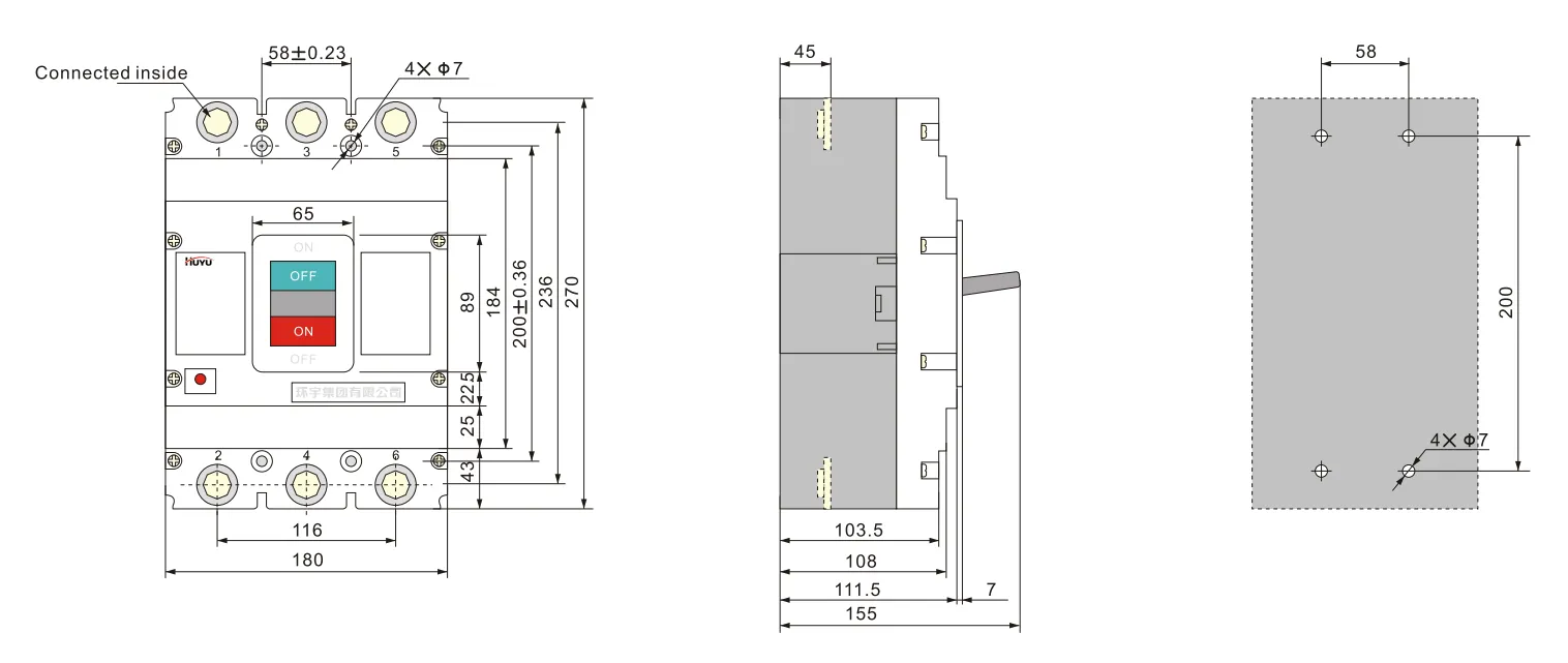
Câblage de type H pour 4P HUM8PV-400 (connexion avant)
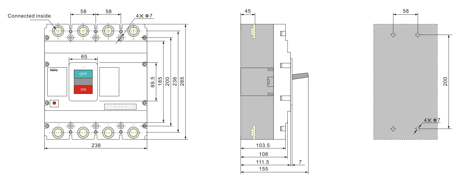
Câblage de type E pour 3PHUM8PV-630 (connexion avant)
Câblage de type H pour 4P HUM8PV-630 (connexion avant)
Accessoires
Les accessoires peuvent être fournis selon les exigences de l’utilisateur.
Paramètres de déclencheur shunt :
Tension nominale Us : AC230V, 400V ; DC 220-250V, 24-30V
Le disjoncteur peut couper de manière fiable à (70%-110%) Us, et le temps d’action est de 10 ms à 30 ms.
Remarque : lors de l’utilisation d’un déclencheur shunt DC24V-30V, la longueur maximale de la ligne en cuivre doit respecter les exigences de la feuille 6
| Tension nominale de commande Us (DC24V~30V) |
Puissance d’entrée | Longueur maximale de la ligne en cuivre | |
| 1,5 mm² | 2,5 mm² | ||
| 100%Us | 50 W | 150 m | 250 m |
| 85%Us | 50 W | 100 m | 160 m |
Valeur nominale du contact auxiliaire et du contact d’alarme :
Courant thermique conventionnel Ith=3A ; courant de travail nominal Ie=0,79A (AC230V) ; Ie=0,47A (AC400V) ; Ie=0,15A (DC250V)
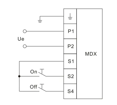
Paramètres du mécanisme de fonctionnement du moteur voir feuille 7, hauteur totale du mécanisme de fonctionnement du moteur voir feuille 8. Le schéma de câblage du mécanisme de fonctionnement du moteur est le suivant
| Courant nominal de la taille du cadre Ie (A) | Tension de service nominale Ue(V) | Courant de démarrage (A) | Temps d’action (s) | Fréquence de fonctionnement nominale (fois/h) | Durée de vie mécanique (fois) |
| 125 | AC 110V~230V 50Hz DC 110V~220V |
≤0,5 | ≤0,8 | 180 | 9000 |
| 250 | |||||
| 400 | ≤2 | 120 | 5000 | ||
| 630 | 3000 |
La capacité de puissance du mécanisme de fonctionnement du moteur doit être suffisante pour garantir que la tension appliquée au courant de démarrage ne soit pas inférieure à 85%Ue
| Modèle | HUM8PV-125 | HUM8PV-250 | HUM8PV-400 | HUM8PV-630 |
| Hauteur | 170 | 199 | 230 | 246 |
Schéma de câblage du mécanisme de fonctionnement du moteur
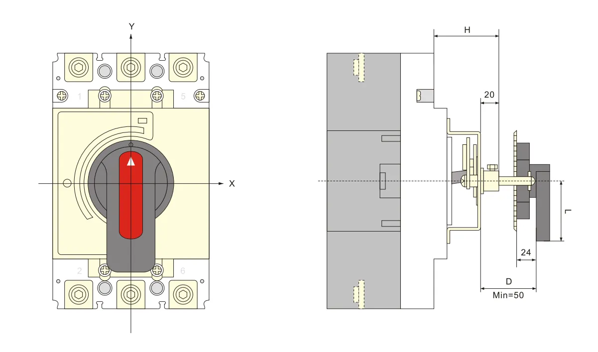
Dimensions de montage du mécanisme de poignée rotative voir feuille 9
| Modèle | HUM8PV-125 | HUM8PV-250 | HUM8PV-400 | HUM8PV-630 |
| Dimensions de montage (H) | 54 | 54 | 76 | 83 |
Dessin global et des trous de montage de la poignée de type A (carré)
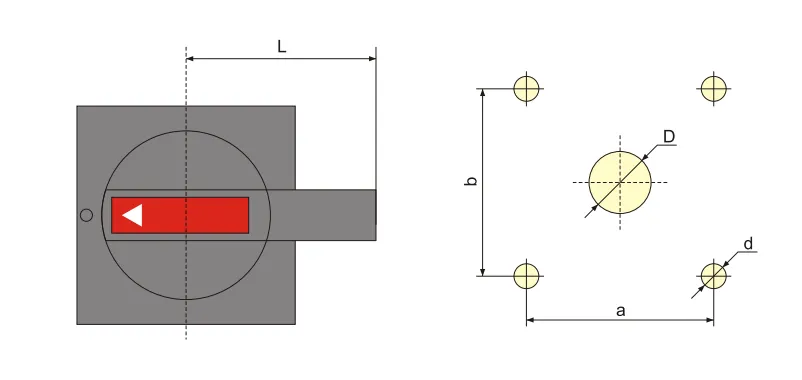
| Modèle et spécification | A1 | A2 |
| D | Milieu 42 | φ 63 |
| d | 中4.5 | φ5.5 |
| a | 65 | 88 |
| b | 65 | 88 |
| L | 60 | 140 |
Dessin global et des trous de montage de la poignée de type B (ronde)
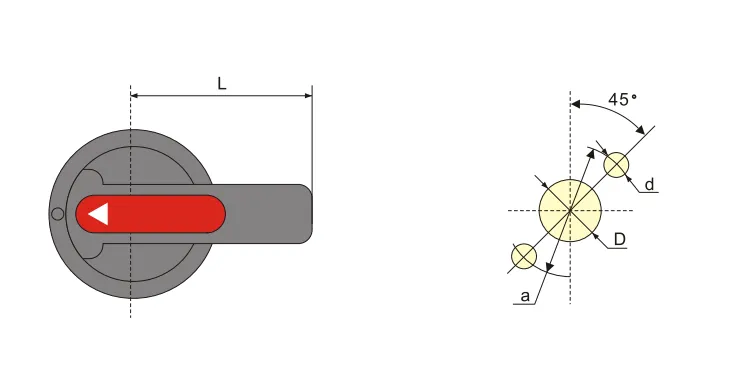
| Modèle et spécification | B1 | B2 | B3 |
| D | φ33 | φ33 | 中33 |
| d | 中4.5 | φ4.5 | 中4.5 |
| a | φ 53 | φ53 | φ53 |
| L | 65 | 125 | 95 |
Dimensions globales et de montage du mécanisme d’opération à poignée rotative centralisée
Installation et maintenance
Points à observer avant l’installation :
a. L’apparence doit être en bon état et l’action sans charge normale ; la valeur nominale du disjoncteur et des accessoires doit correspondre aux conditions de travail sur le site de montage ; pas de choc évident sur le site de montage et conforme aux conditions de travail normales
b. Un test d’isolation doit être effectué avant la sortie d’usine. Utilisez un mégohmmètre 1000VDC pour refaire le test avant l’installation, entre les pôles du disjoncteur, la résistance d’isolement entre la même borne d’entrée et de sortie doit être d’au moins 20MΩ en état de coupure
La section transversale des conducteurs doit dépasser la taille réglementée dans la feuille 10, et le boulon de connexion doit être serré.
Les caractéristiques du disjoncteur et des accessoires doivent répondre à nos exigences de commande.
La poignée du disjoncteur peut tourner aux positions “ on ”, “ off ”, “ trip ” ; lorsqu’elle est en position “ trip ”, la poignée tournée vers la direction “ off ” peut ensuite effectuer l’opération “ on ”.
Avant d’ajouter les accessoires internes, le déclencheur du disjoncteur doit être éteint.
| Courant nominal (A) | 10 | €�20 | 25 | 32 | €�50 | 63 | 80 | 100 | 125 | 160 | €�200、225 | 250 | €�350 | 400 |
| Section transversale du conducteur | 1.5 | 2.5 | 4 | 6 | 10 | 16 | 25 | 35 | 50 | 70 | 95 | 120 | 185 | 240 |
| Courant nominal (A) |
Section transversale du câble | Taille de la barre en cuivre | ||
| Quantité | Section transversale (mm²) | Quantité | Taille (mm×mm) | |
| 500 | 2 | 150 | 2 | 30×5 |
| 630 | 2 | 185 | 2 | 40×5 |
Informations de commande
Nom du produit et modèle
Courant nominal, type de déclenchement, multiple du courant de réglage du déclenchement instantané
Nom et spécification des accessoires
FAQ
Qu’est-ce qu’un disjoncteur moulé ?
Un disjoncteur moulé (MCCB) est un dispositif de protection enfermé dans un boîtier moulé. Il offre une protection contre les surintensités et les courts-circuits pour les circuits électriques, avec des réglages de déclenchement ajustables et des capacités de coupure supérieures à celles des disjoncteurs miniatures.
Qu’est-ce qu’un disjoncteur photovoltaïque ?
Un disjoncteur photovoltaïque est spécialement conçu pour les applications solaires en courant continu. Il gère les caractéristiques uniques des systèmes PV — tensions DC plus élevées (jusqu’à 1000V ou 1500V DC), extinction d’arc DC sans passage par zéro, et variations continues de charge dues à l’irradiance solaire.
Quelle est la différence entre un disjoncteur et un disjoncteur moulé ?
Un “ disjoncteur ” est un terme général pour tout dispositif automatique de protection contre les surintensités. Un “ disjoncteur moulé ” (MCCB) est un type spécifique — logé dans un boîtier isolant moulé, avec des courants nominaux plus élevés (jusqu’à plusieurs milliers d’ampères), des réglages de déclenchement ajustables, et des capacités de coupure supérieures à celles des disjoncteurs miniatures (MCB).
Lequel est meilleur, ACB ou MCCB ?
Aucun n’est universellement “ meilleur ” — ils servent des applications différentes. L’ACB (Disjoncteur à air) est utilisé pour la distribution principale basse tension (courant élevé, jusqu’à 6300A), avec une protection réglable et une haute capacité de coupure. Le MCCB (Disjoncteur à boîtier moulé) est utilisé pour la protection des circuits dérivés (jusqu’à 1600A), plus compact et économique pour les circuits d’alimentation. Choisissez en fonction de la valeur nominale du courant de l’application et des exigences de protection.