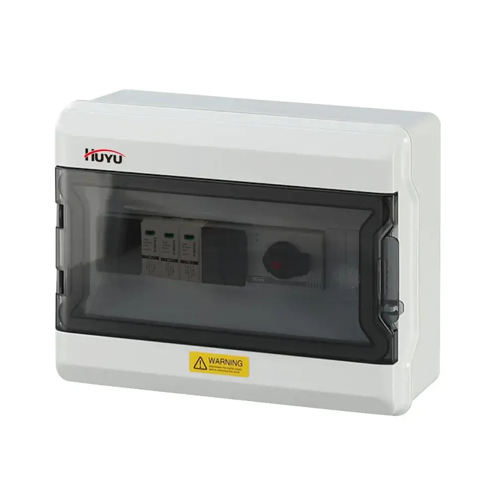
EXCB3-DC2-1 – 2 String Isolator DC Combiner Box
The EXCB3-DC2-1 is a 2-string isolator DC combiner box with DC isolator switches on each input for visible load-break isolation. Rated 32A, 600V/1000V DC. Integrated Type 2 SPD (40kA) and optional fuses. IP65 outdoor enclosure. CE, TUV certified. Wall-mount. Ideal for residential PV and off-grid systems where manual isolation is paramount.
Standards: IEC/EN 60947-3, EN 50539-11, UL 508I
String Configuration: 2 Inputs, 1 Output
Switch Type: DC Isolator (DC-PV1/DC-PV2)
Rated Current: 32A
Max. Voltage: 600V / 1000V DC
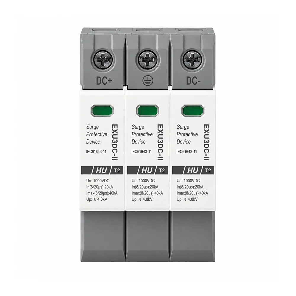
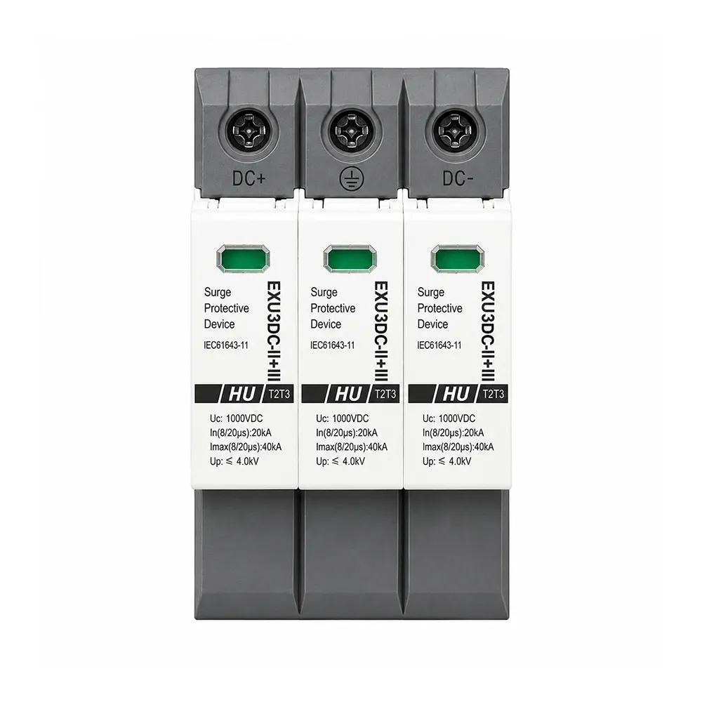
SPD: Type 2, 40kA
Enclosure: IP65, UV-resistant
Product Information
EXCB3-DC2-1 Isolator DC Combiner Box – Reliable and Visible Isolation for Small-Scale PV Systems
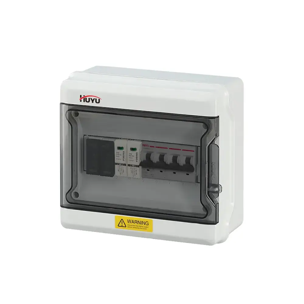
The EXCB3-DC2-1 isolator DC combiner box from HUYU Electric is tailored for small-scale photovoltaic systems where visible, manual disconnection ensures maximum safety. This unit stands out by incorporating DC isolator switches for both input strings and the combined output, eliminating reliance on DC circuit breakers alone. Each isolator offers an easy-to-see open circuit, empowering maintenance teams to ensure safe disconnection. Rated at 32A with a maximum operating voltage of 600V or 1000V DC, the EXCB3-DC2-1 fits neatly into residential rooftops, off-grid solar setups, and distributed PV systems.
Encased in a durable IP65 enclosure, the EXCB3-DC2-1 also integrates a Type 2 surge protective device (40kA Imax) along with optional DC fuses (15A–32A). Pre-assembled and tested internal wiring streamlines installation, leaving solar installers with just the task of connecting the PV strings and inverter feed cables. For EPC contractors and professional installers seeking a dependable PV DC isolator box that conforms to safety protocols, HUYU Electric delivers OEM/ODM-ready solutions that meet CE, TUV, and CB certifications.
Technical Specifications – EXCB3-DC2-1
| Parameter | Value |
|---|---|
| Model | EXCB3-DC2-1 |
| DC Input / Output | 2 Strings In / 1 String Out |
| DC Switch Type | DC Isolator Switch (Manual, Visible Break) |
| Rated Current of Isolator | 32A |
| Max. Operating Voltage | 600V / 1000V DC |
| DC Isolator Classification | DC-PV1 / DC-PV2 |
| DC SPD Type / Imax | Type 2 / 40 kA |
| DC Fuse (Optional) | 15A – 32A, Φ10 × 38 mm, 1000V |
| Enclosure Rating | IP65 (UV-resistant) |
| Certifications | CE, TUV, CB |
| Operating Temperature | -20°C to +60°C |
| Installation | Wall-mounted |
Request a Quotation for EXCB3-DC2-1 Combiner Boxes
2-input, 1-output, 32A DC isolator switches, 1000V DC, Type 2 SPD, IP65. CE, TUV certified. Factory-direct OEM/ODM options with custom branding. Contact us for project pricing and production timelines.
Quotation for Projects • IEC/EN 60947-3 Compliance • Global Shipping
Understanding Isolator vs Breaker Combiner Boxes
Key details to help you select the optimal combiner box for your PV system.
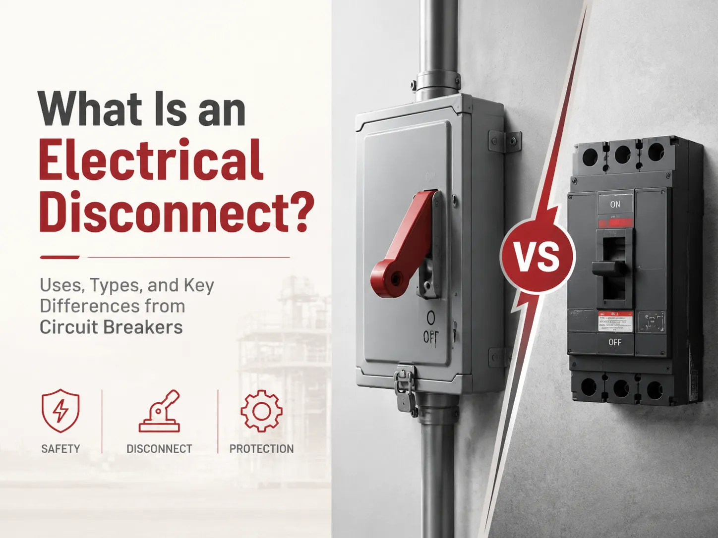
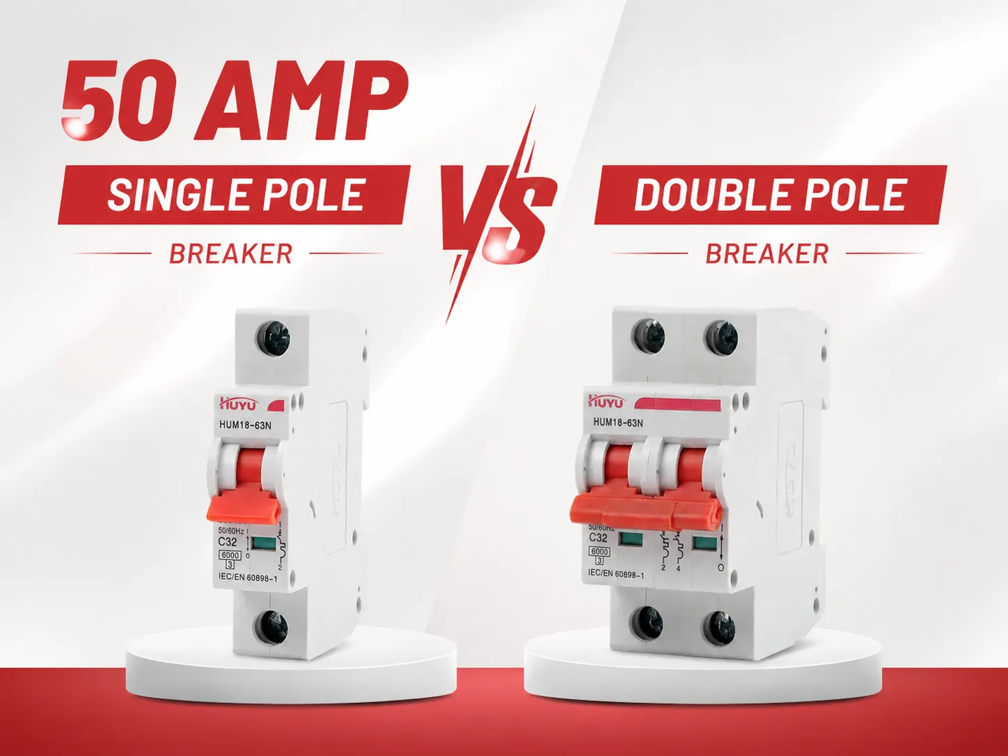
1. Breaker vs. Isolator: Key Differences
A DC circuit breaker (MCB) trips automatically during overcurrent issues and can be reset, while a DC isolator is manually operated for a clear and visible disconnection. The EXCB3-DC2-1 prioritizes safety, employing isolators to provide a reliable manual disconnect option, ideal for setups requiring visible isolation without automatic tripping. This is particularly beneficial for systems with external overcurrent protection or specific circuits, like battery charging setups from PV arrays.
2. Selecting Suitable String Configurations
The EXCB3 series offers versatile configuration options, ranging from 1-1 to 6-1 models. Residential installations commonly use the EXCB3-DC2-1 model designed for dual parallel strings, while single-string systems may opt for the cost-effective EXCB3-DC1-1 model. For larger systems, consider higher-string models like the EXCB3-DC3-1 or EXCB3-DC6-1 for additional capacity and isolation options.
3. Adding DC Fuses for Enhanced Safety
While manual isolation is crucial, complementary fuse protection can be implemented within the EXCB3-DC2-1, accommodating 15A–32A DC fuses to protect individual strings from overcurrent issues. Proper fuse configuration ensures system reliability by isolating faults without disrupting other circuits.
4. Ensuring Durability Outdoors
Designed for outdoor use, the EXCB3-DC2-1 features high-grade UV-resistant IP65 enclosures for enhanced weather protection. Proper installation practices, including vertical position and downward cable gland orientation, safeguard against water ingress and ensure efficient operation in diverse environments.
Frequently Asked Questions
What is the purpose of a PV combiner box?
A PV combiner box aggregates the outputs of several solar strings into one DC output while also incorporating DC isolators for manual and visible disconnection. For instance, the EXCB3-DC2-1 features isolator switches, surge protection, and optional fuses within a weatherproof IP65-rated enclosure. This ensures enhanced safety during maintenance and protection against potential electrical faults.
What does the 33% rule mean?
The “33% rule” guides combiner box designing by recommending the internal components to occupy no more than one-third of the enclosure’s total volume. Adhering to this rule supports optimal air circulation and heat dissipation, ensuring reliable operation of components like isolator switches and wiring over time.
Why are some solar systems being decommissioned?
Common reasons include roof repairs, system inefficiencies, or financial constraints. Technical issues, such as poor isolation of circuits or water invasion into subpar combiner boxes, are frequent causes. High-quality solutions, like the EXCB3-DC2-1 with robust DC isolator switches, mitigate these risks by simplifying maintenance and ensuring long-lasting protection.
How to install a PV combiner box?
To install the EXCB3-DC2-1, mount the weatherproof unit near your PV array and ensure disconnect switches are turned off. Connect DC cables from your PV strings to input terminals via designated glands, followed by the output cable to the inverter. Attach the earth wire securely to the terminal, confirm all connections, and close the enclosure. Turn on isolator switches to energize the system, strictly following local regulations and installation guidelines.
No documents available for download at this moment.