
Uma correia transportadora fica presa. O motor consome 38 amperes do circuito que é classificado para apenas 32 amperes por uma duração de 90 segundos enquanto alguém vai consertá-lo. Tudo está intacto. O disjuntor e todos os seus contatos também estão intactos. Embora a bobina eleve sua temperatura 40 graus Celsius acima do limite indicado na placa do motor, o isolamento sofre danos e queima dentro de 3 semanas. Um engenheiro elétrico é o responsável. Um novo motor é comprado. Outra falha ocorre dentro de 3 meses.
A distância entre as afirmações “o consumo de energia foi muito grande” e “a proteção do circuito funcionou” é exatamente a distância que os geradores foram desenvolvidos para cobrir. Situações envolvendo essa distância estão entre as ocorrências mais comuns de instalação e ajuste incorretos dos elementos de proteção do motor.
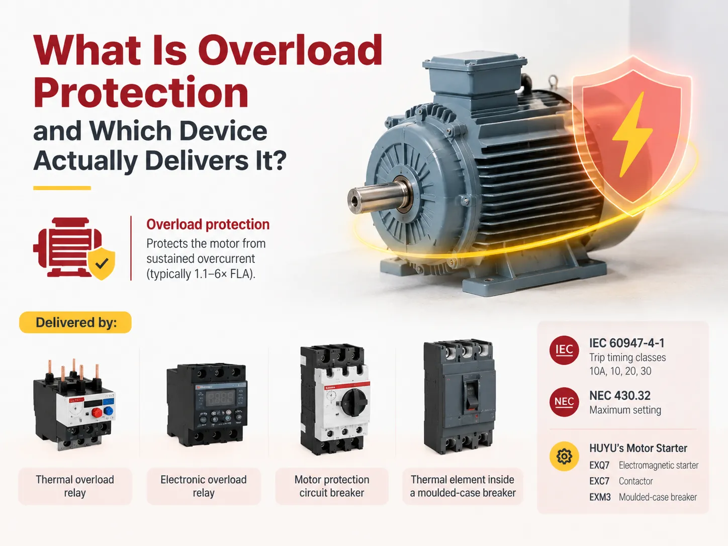
De acordo com a resposta rápida, a proteção contra sobrecarga é um tipo de temporização inversa que protege o motor contra corrente prolongada acima do seu limite operacional nominal, mas abaixo do valor de um curto-circuito. Esse tipo de proteção é fornecido por um relé térmico de sobrecarga, um relé eletrônico de sobrecarga, um disjuntor motor ou o elemento térmico presente dentro de um disjuntor moldado. Os tempos são ditados pela IEC 60947-4-1 usando as classes 10A, 10, 20 e 30, e o limite superior da regulagem é determinado pela NEC 430.32. A HUYU fabrica os partidas eletromagnéticos ExQ7, os contatores ExC7 e os disjuntores moldados ExM3 para cumprir essa função nas partidas de motor.
O Que a Proteção Contra Sobrecarga Cobre, e O Que Não Cobre
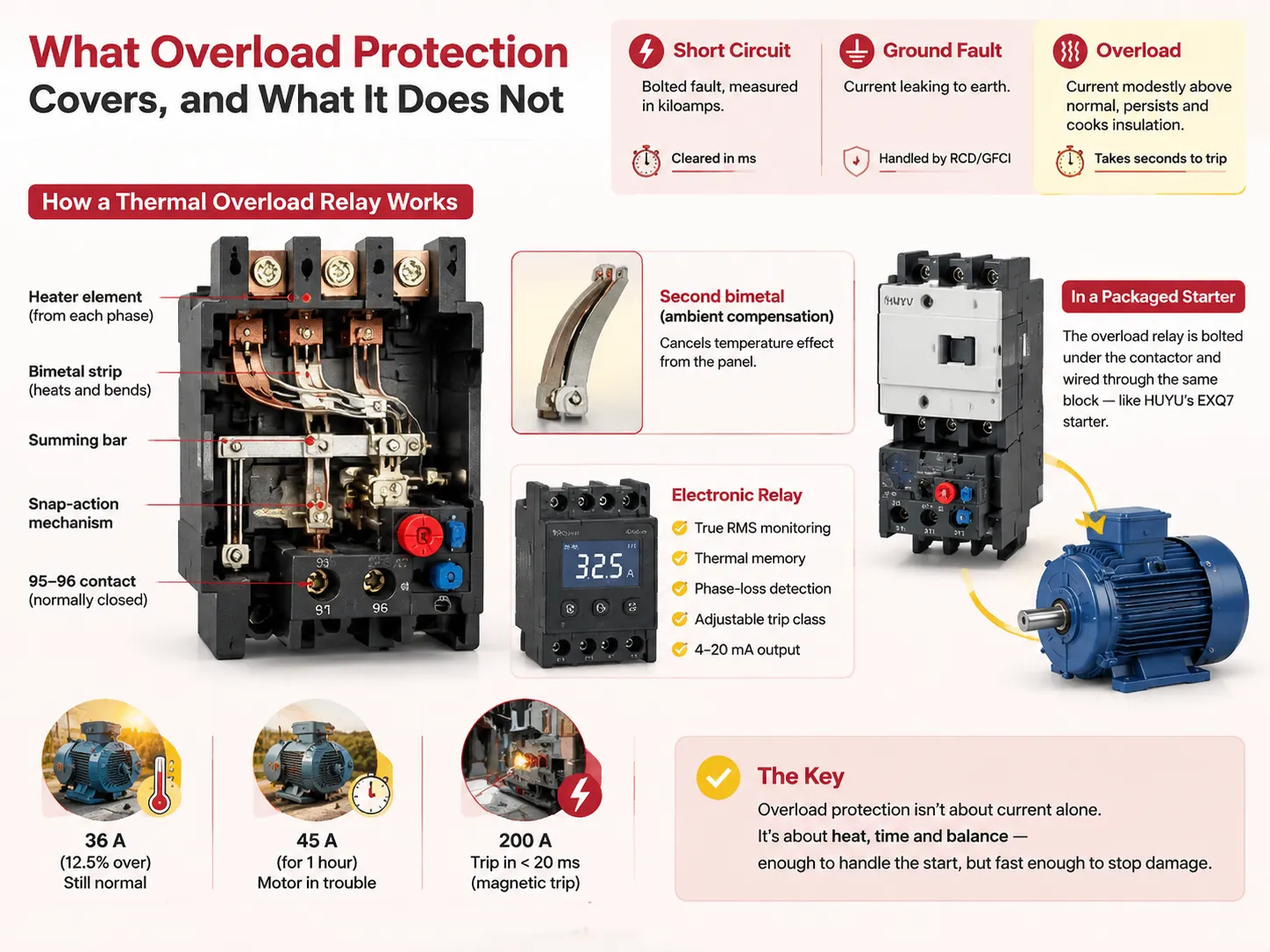
Existem três tipos de falhas que são frequentemente confundidas. Curto-circuito refere-se a uma falha instantânea que possui uma corrente de falha medida em kiloamperes e dura apenas milissegundos. Falha à terra ocorre quando a corrente de falha vai para a terra e é tratada por um RCD ou GFCI. Sobrecarga está entre essas duas categorias; ocorre quando a corrente está ligeiramente acima do normal por um tempo prolongado.
No entanto, as diferenças são muito menores do que as pessoas pensam. Um motor de 32 A que opera a 36 A está 12,5% sobrecarregado, o que é aceitável em um dia quente de verão, mas se esse mesmo motor funcionar a 45 A, o enrolamento sofrerá superaquecimento. Um caso de operação a 200 A implicaria que a proteção magnética deveria disparar em menos de 20 milissegundos.
Por causa disso, a proteção contra sobrecarga precisa funcionar de forma visivelmente mais lenta. Baseando-se no calor e não apenas na corrente, isso significa que se um dispositivo disparar após dois segundos atingindo 1,5 vezes a corrente de plena carga, ele falhará em cada partida do dispositivo. Ele precisa suportar o tempo de partida enquanto reconhece o superaquecimento ao mesmo tempo.
Como o Disparo Realmente Acontece
Um relé térmico é projetado de forma que contenha dois componentes metálicos com habilidades de expansão diferencial. Por exemplo, a ação de flexão permite alcançar um limite pré-definido para acionar o mecanismo de disparo instantâneo caso a flexão ultrapasse um certo nível.
Além disso, um segundo bimetal alimentado pela temperatura ambiente aquece o outro, que é responsável pelo funcionamento do motor. No caso de não haver circulação de ar no invólucro a uma temperatura de 50°C, o relé pode disparar indesejadamente durante todo o verão ou no final do inverno.
Relés eletrônicos modernos utilizam transformadores e microcontroladores para fornecer leituras RMS verdadeiras por meio de amostragem. Eles também são capazes de adicionar funções como memória térmica e detecção de perda de fase, além de classe de disparo ajustável e, muito frequentemente, uma saída de 4–20 mA. Em um motor de partida embalado, o relé é fixado diretamente sob o contator e conectado através do mesmo bloco de sobrecarga, que é como o HUYU’s motor de partida eletromagnético EXQ7 combina seu contator com o elemento de sobrecarga em uma única montagem em vez de dois itens separados para trilho DIN.
A Classe de Disparo Decide o Tempo
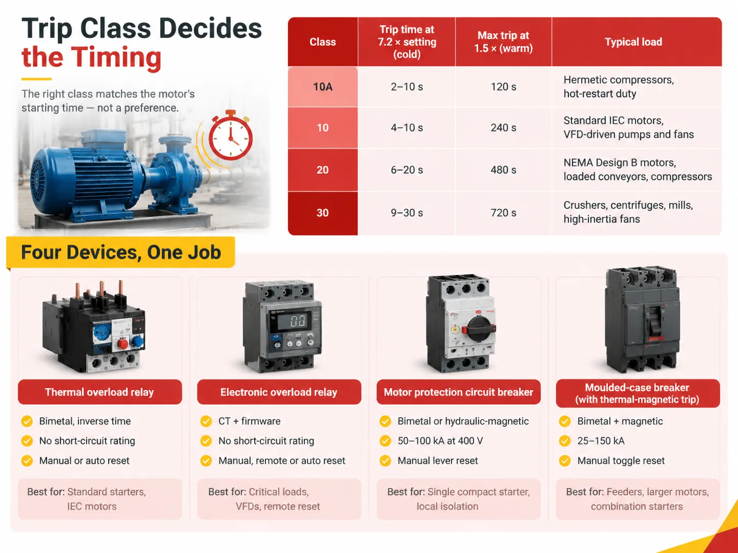
O número da classe é definido na IEC 60947-4-1 como o tempo máximo de disparo expresso em segundos a um fator de 7,2 da corrente de disparo a partir de uma condição quente. A mesma norma estipula um limite superior de 1,05 vezes, de modo que o relé não pode disparar, e um limite inferior de 1,2 vezes, de modo que o relé deve disparar em no máximo duas horas.
| Classe | Tempo de disparo a 7,2 × ajuste (frio) | Disparo máximo a 1,5 × (quente) | Carga típica |
|---|---|---|---|
| 10A | 2–10 s | 120 s | Compressores herméticos, operação de reinício a quente |
| 10 | 4–10 s | 240 s | Motores IEC padrão, bombas e ventiladores acionados por VFD |
| 20 | 6–20 s | 480 s | Motores NEMA Design B, transportadores carregados, compressores |
| 30 | 9–30 s | 720 s | Trituradores, centrífugas, moinhos, ventiladores de alta inércia |
A escolha da classe é sempre ditada pelo tempo de partida e não depende da preferência pessoal. Uma bomba que recebe Classe 10 está corretamente classificada quando opera em velocidade máxima em apenas três segundos. Por outro lado, um ventilador centrífugo de 200 kW que leva 25 segundos para atingir a velocidade máxima exigirá Classe 30 para não causar o disparo do relé ao ser iniciado em condições normais, e o operador precisará girar o botão para desabilitar o sistema de proteção.
Essa lógica pode ser aplicada ao caso dos protetores de circuito de motor e disjuntores moldados. Esses dispositivos podem não ser usados como substitutos um do outro em motores de partida. Existem protetores de circuito de motor que funcionam apenas com o princípio magnético e não possuem o elemento térmico incorporado, o que significa que nenhuma proteção térmica pode ser realizada. As diferenças são apresentadas nesta comparação de um protetor de circuito de motor contra um disjuntor, e elas são importantes quando você está solicitando um motor de partida a partir de uma lista de materiais escrita por outra pessoa.
Os Quatro Dispositivos Que Realizam Este Trabalho
| Dispositivo | Elemento de sobrecarga | Classificação de curto-circuito | Redefinir | Melhor ajuste |
|---|---|---|---|---|
| Relé térmico de sobrecarga | Bimetal, tempo inverso | Nenhum, necessita de backup | Manual ou automático | Motores de partida padrão, motores IEC |
| Relé eletrônico de sobrecarga | TC mais firmware | Nenhum, necessita de backup | Manual, remoto ou automático | Cargas críticas, VFDs, reset remoto |
| Disjuntor de proteção de motor | Bimetal ou hidráulico-magnético | Included, typically 50–100 kA at 400 V | Manual lever | Single compact starter, local isolation |
| Moulded-case breaker with thermal-magnetic trip | Bimetal plus magnetic | Included, 25–150 kA | Manual toggle | Feeders, larger motors, combination starters |
See what is missing from the table? There is no one of these four options that is better than another. A thermal relay surveys for $25 and performs one function and does it with no firmware versioning. The motor protection circuit breaker has a price of three times the thermal relay and does away with the short-circuit detection component, as well as the wiring. All of it results in smaller panels and simpler assembly for a 500-motor project.
How the Devices Differ in Practice
Thermal relays are not reliable. The bimetal deteriorates, and the calibration may change by several percent over a time period of ten years. For example, when the relay was new, it had a limit of 1.15, but after 8 years in the hot environment of the cabinet, it is likely to change to 1.30. It is common practice to check the thermal relay once a year by introducing 1.5 times the current. This check takes around ten minutes per relay with the proper test device.
Electronic relays are much better in keeping the calibration and offer extras that solve real problems. The thermal memory feature of electronic relays prevents the restarting and retrying cycle that damages the windings. The phase-loss detection capability enables electronic relays to capture the most harmful overload possible for the motor since kicking on two phases, the motor will draw about 1.7 to 2 times the ten-pole power in the remaining windings while the third is not active, and a simple three-bimetal relay will be too slow because only 2 elements can be heated.
As for contactors, there is no point in outrunning the relay if the contactor does not survive the task. HUYU’s EXC7 AC contactor is rated for AC-3 motor duty with the utilisation category printed on the nameplate, and matching that category to the actual switching task is a bigger deal than matching the amp rating, which is the number most buyers compare.
Matching the Device to the Load
Fans and pump systems which start unloaded are straightforward case; Class 10, nameplate FLA with the use of ambient compensation is sufficient.
Conveyors and screw compressors run loaded but start against torque. Class 20 is applicable for a NEMA motor having 1.15 service factor. In this case the setting is at nameplate FLA when the motor is loaded during normal operating mode.
Submersible pumps, hermetic refrigeration compressors and all VFD-driven systems start with play of Class 10 or 10A. VFD limits starting current, making overload relay protect against slow thermal event rather than starting; faster class grants better winding protection without nuisance trips.
Crushers, mills and large induced draft fans have significant amount of rotating mass, so it takes 20 to 60 seconds for acceleration. Class 30 exists for such processes.When the load is genuinely this heavy, the failure mode to watch is not the trip but the contactor holding a stalled motor at locked-rotor current for a minute at a time, and the symptoms of that abuse show up long before the motor fails, as this guide to contactor failure symptoms describes.
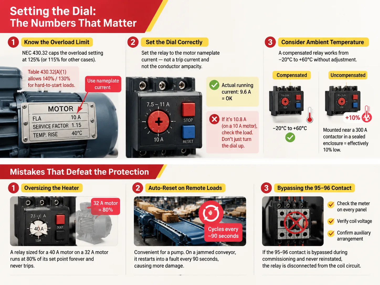
Setting the Dial: The Numbers That Matter
NEC 430.32 restricts overload settings to 125% of a motor’s rated full-load current for motors that have either a temperature rise of 40°C or less or a service factor of 1.15 or more. Otherwise, the limit is set at 115%. According to Table 430.32(A)(1), 140% and 130% can be utilized, respectively, where the motor will not start at the lower setting.
Set the dial to the nameplate current of the motor as opposed to the trip current and the ampacity. A 7.5–11 A relay set at 10 A would not trip at 10.5 A but would trip at 12 A within two hours. For example, if a clamp meter measures the running current to be 9.6 A, the setting is good and shows no need for further adjustments. If the reading is 10.8 A, indicating a problem with the load, simply increasing the dial reading to 12 A will lead to further complications.
The setting for ambient temperature takes its place second. A compensated relay will be able to work within a range of −20°C to +60°C without being adjusted. An uncompensated relay installed next to a 300 A contactor would have been set 10% low and compensatory adjustments would have been made by simply turning the dial up, which is not the right way to correct the setting.
Mistakes That Defeat the Protection
The frequent mistake is using a heater that is too large. When a relay that is designed for a motor that consumes 40 A works together with a device that needs 32 A, it operates at 80 % of the correct level and does not turn off, which means that it does not provide protection until the drive coil has burned out.
The other issue is self-resetting devices used for remote equipment. While using self-resetting devices on a pump that goes off once a season is fine, having them activate every 90 seconds with jammed conveyor makes the situation worse than with the jam itself.
Furthermore, people often bypass the 95–96 contacts during installation because the starter is failing to latch into position and do not even turn it back on after that. Although the relay has been properly calibrated, it does not work properly anymore. It is advisable to check the system every now and then to make sure that the overload protection is not connected to the faulty coil and testing the system with a meter is not a bad idea either.
FAQ
Is overload protection the same as surge protector?
No, nor can be used interchangeably. A surge protector grabs a transient voltag spike which takes place over microseconds and does not deal with current at all. Overload protection acts after being exposed to sustained overcurrent over seconds or minutes. A panel can and usually does need both, and the way they interact in a service entrance is covered in the comparison of a circuit breaker versus a surge protector.
What is the simplest form of overload protection?
A thermal overload relay consists of a bimetal element that is connected in series with the contactor coil through the 95-96 contact. There are two wires for input and output each, as well as the current setting knob and a manual reset button. It does not require any auxiliary power source or configuration, which is why it continues to be a first choice for general-purpose starters.
What does “no overload protection” mean?
It suggests the circuit is shielded solely from short circuits and ground faults. A magnetic breaker or a group of fuses will keep a motor running at 150% of its rated current continuously since 150% is quite a distance from the magnetic tripping point. Unfortunately, the motor will fail, but it will fail thermally rather than dramatically.
What does an overload protector do?
It monitors the electric current, simulates the heat generated in the winding of the motor electric motor circuit, and disconnects the control circuit when the heat exceeds the limit of the winding. The output action does not involve tripping the main contacts but only dropping the coil of the contactor, thus the overload contact is wired into the control circuit rather than the power circuit.
Referências
- ABB — Motor Starting and Protection Portfolio
- Rockwell Automation — Allen-Bradley Motor Control
- NFPA 70 — National Electrical Code, Article 430
- UL 508 — Industrial Control Equipment
- Electrical Engineering Portal — Motor Protection Reference
Conclusão
Thermal overload protection is considered to be a hardware component. The device has to be able to withstand a 600% startup current and must be able to respond to the load growing more than 40% above normal within seconds. The class number indicates the patience of the device while the current dial indicates what is considered normal and NEC 430.32 indicates the upper limits for both.
If these three are correct, the device almost does not matter. If, however, these three parameters are wrong, the most expensive relay will not protect at all, which is the occurrence that cannot appear on diagrams even in cases when the panel is fully equipped with 95–96 properly rated and set contacts.