
Se você procurar a ampacidade do fio 8 AWG na internet, frequentemente encontrará respostas como 40, 50 ou 55 amperes. Essas afirmações coincidem, pois as pessoas se referem à mesma tabela e a entendem corretamente. A diferença está em outros aspectos que não estão relacionados ao cobre, como a classificação da isolação, a classificação de temperatura dos terminais e a presença de ar livre.
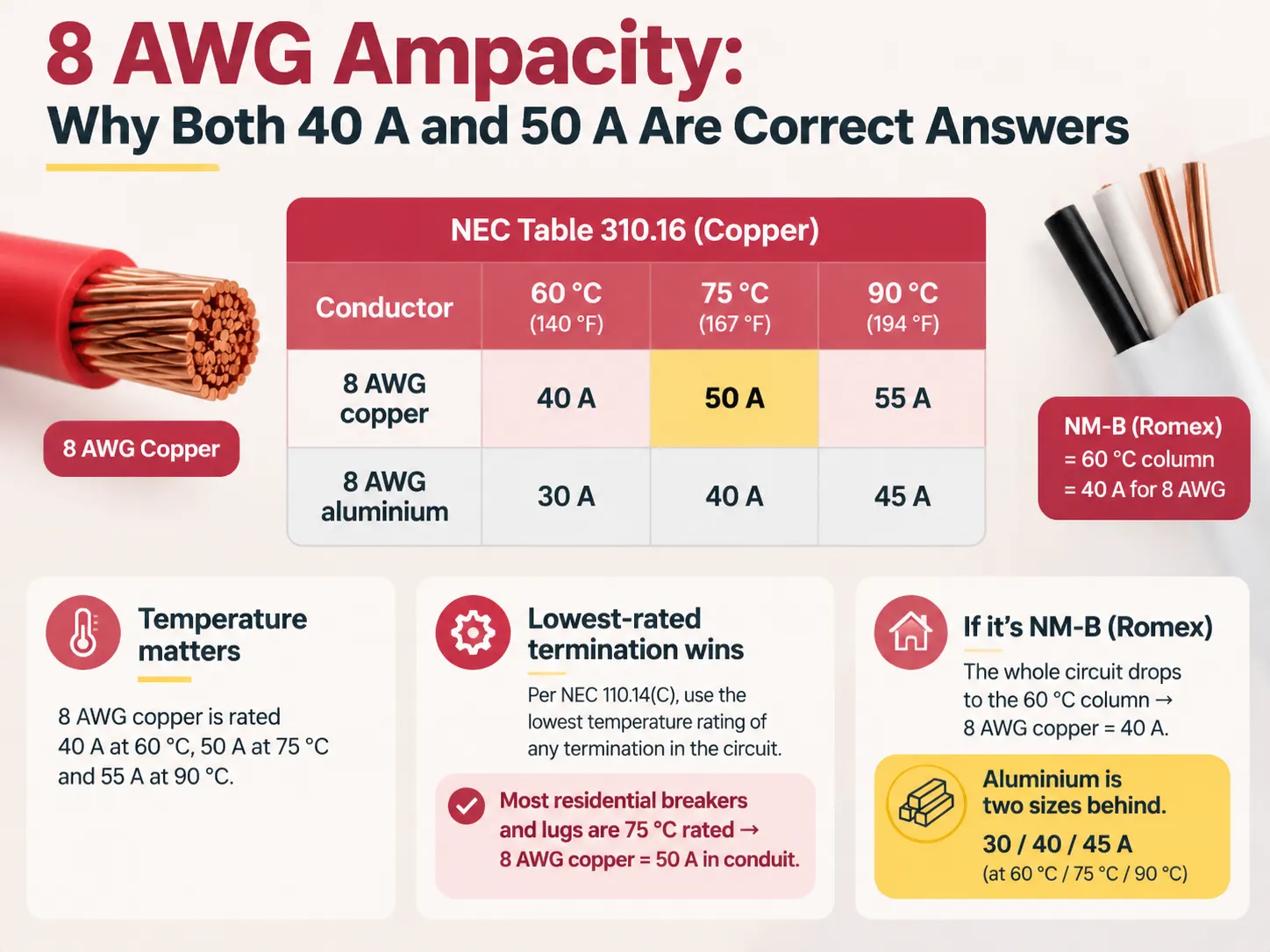
Resumidamente, a classificação para cobre calibre 8 é cerca de 40 A a 60 graus Celsius, 50 A a 75 graus Celsius e 55 A a 90 graus Celsius, conforme mostrado na tabela 310.16 do NEC. A classificação a ser usada será a menor classificada no circuito, conforme declarado pelo código NEC 110.14(c): já que na maioria das residências, os terminais e disjuntores são classificados para 75 graus, tornando assim o cobre calibre 8 um condutor de 50 A em conduíte. Qualquer fiação no percurso feita em conduíte NM-B (Romex) fará a classificação cair para a coluna de 60 graus, tornando-o um condutor de 40 A.
O que 8 AWG Realmente É
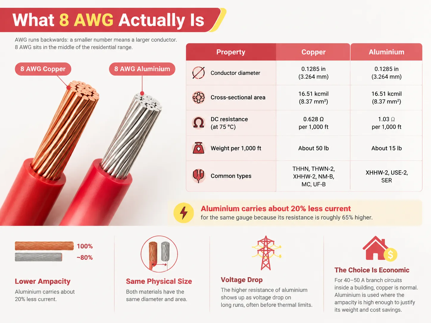
American Wire Gauge é invertido; quanto menor o número, maior o fio. 8 AWG está no meio da faixa residencial, acima dos calibres 14, 12 e 10 AWG usados para circuitos ramais regulares, mas abaixo dos calibres 6 e 4 AWG que são usados para alimentadores maiores e entradas de serviço.
| Propriedade | Cobre | Alumínio |
|---|---|---|
| Diâmetro do condutor | 0,1285 pol (3,264 mm) | 0,1285 pol (3,264 mm) |
| Área da seção transversal | 16,51 kcmil (8,37 mm²) | 16,51 kcmil (8,37 mm²) |
| Resistência DC a 75 °C | 0,628 Ω por 1.000 pés | 1,03 Ω por 1.000 pés |
| Peso por 1.000 pés | Cerca de 50 lb | Cerca de 15 lb |
| Tipos comuns | THHN, THWN-2, XHHW-2, NM-B, MC, UF-B | XHHW-2, USE-2, SER |
Embora ambos os metais tenham o mesmo tamanho, eles se comportam de maneira muito diferente. O alumínio tem cerca de 20% menos ampacidade do que o mesmo calibre de fio em cobre. Isso ocorre porque sua resistência é aproximadamente 65% maior que a resistência do cobre. O resultado é que a diretriz da indústria para alumínio sugere que ele tende a ser dois calibres abaixo do cobre. Para longos trechos de fio, a diferença na resistência se manifesta como uma queda de tensão antes de atingir a limitação térmica.
A escolha entre os dois geralmente é econômica em vez de técnica, e tem uma longa história tanto do lado da concessionária quanto do lado do circuito ramal de uma instalação — o raciocínio por trás disso está explicado nesta explicação de por que cobre e alumínio são ambos usados para transmissão de energia. Para um circuito ramal de 40 ou 50 amperes dentro de um edifício, o cobre é a resposta normal; o alumínio aparece principalmente onde a ampacidade é grande o suficiente para que a economia de peso e custo compense o aumento de calibre.
A Tabela de Ampacidade, e Por Que Existem Três Colunas
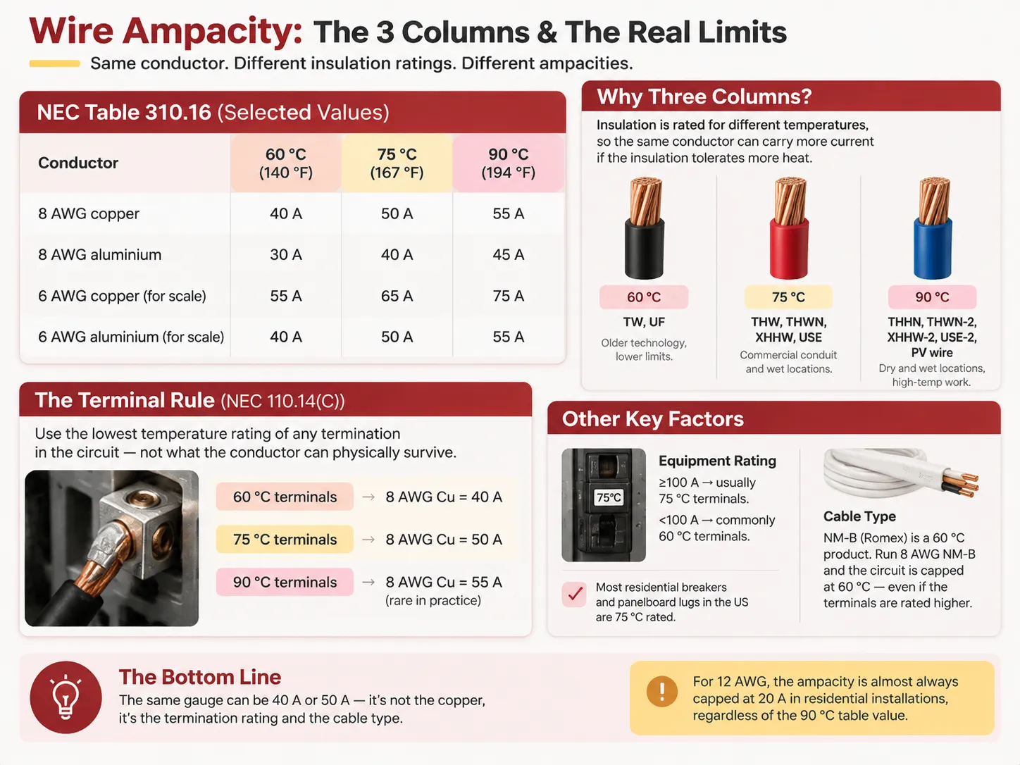
Os números foram obtidos da Tabela 310.16 do NEC, que indica as ampacidades permitidas de condutores isolados de no máximo 2000 V e operando a uma temperatura de 30 °C com no máximo três condutores de corrente em um conduíte ou cabo.
| Condutor | 60 °C (140 °F) | 75 °C (167 °F) | 90 °C (194 °F) |
|---|---|---|---|
| 8 AWG cobre | 40 A | 50 A | 55 A |
| 8 AWG alumínio | 30 A | 40 A | 45 A |
| 6 AWG cobre (para escala) | 55 A | 65 A | 75 A |
| 6 AWG alumínio (para escala) | 40 A | 50 A | 55 A |
As colunas são necessárias porque o isolamento foi produzido com diferentes classificações de temperatura, e o condutor pode transportar mais corrente antes de superaquecer como resultado do isolamento capaz de tolerar a temperatura esperada.
- Isolamento de 60 °C: TW, UF. Tecnologia mais antiga, limites inferiores.
- Isolamento de 75 °C: THW, THWN, XHHW, USE. Eletroduto regular, locais úmidos de aplicações comerciais.
- Isolamento de 90 °C: THHN, THWN-2, XHHW-2, USE-2, fio PV. Locais secos e úmidos juntamente com condições de trabalho em alta temperatura.
Uma coisa a destacar sobre 90 °C é que frequentemente causa confusão ao lidar com fios desse tamanho porque a coluna de 90 °C é uma base de redução e não uma classificação que deve ser usada para terminação. Ela é usada para determinar como a temperatura ambiente e o agrupamento de condutores afetam os cálculos, e somente então pode ser verificada contra a coluna de temperatura que pode ser usada para terminações específicas. 55 A não pode ser usada como um valor derivado para cobre 8 AWG pois viola o código. Como a determinação da ampacidade funciona passo a passo, incluindo os fatores de correção e ajuste, é abordado neste guia de como a ampacidade mínima do circuito é estabelecida.
A Regra da Terminação Que Decide a Resposta
De acordo com NEC 110.14(C), devo selecionar a ampacidade do condutor com base na classificação de temperatura mais baixa de qualquer terminação, não na temperatura máxima suportável do isolamento do condutor. Em outras palavras, o fator limitante são as conexões e não o condutor em si.
Na prática:
- Terminais classificados para 60 °C → deve ser usada a coluna de 60 °C → cobre 8 AWG = 40 A.
- Terminais classificados para 75 °C → deve ser usada a coluna de 75 °C → cobre 8 AWG = 50 A.
- Terminais classificados para 90 °C → deve ser usada a coluna de 90 °C → cobre 8 AWG = 55 A – o que, na prática, quase nunca se aplica.
Equipamentos classificados para 100 A ou mais normalmente recebem uma listagem para terminações classificadas para 75 °C, enquanto equipamentos classificados abaixo de 100 A normalmente são listados para terminações classificadas para 60 °C; daí de onde vem os 40 A. A maioria dos disjuntores residenciais e barramentos de painéis vendidos nos EUA são classificados para 75 °C, permitindo um grande número de aplicações específicas na vida real com cabos 8 AWG a 50 A – desde que as classificações reais tenham sido verificadas em relação às informações do rótulo do disjuntor, listagem do painel e placa de identificação do aparelho.
Os segundos 40 A vêm do tipo de cabo. NM-B, comumente conhecido como Romex, é um cabo de 60 °C, o que significa que condutores 8 AWG em NM-B vão classificar todo o circuito usando a coluna inferior mesmo que outras conexões sejam classificadas para temperaturas mais altas. Como resultado, a mesma bitola pode ser usada como condutor de 40 A em uma aplicação e 50 A em outra a apenas seis metros de distância.
A mesma lógica explica por que 12 AWG é limitado a 20 A em quase todas as situações residenciais, embora um condutor 12 AWG isolado para 90 °C possa transportar 30 A na tabela. Abaixo de 8 AWG os números são fixados pela regra do condutor pequeno; em 8 AWG eles não são, o que torna esse tamanho genuinamente dependente dos detalhes da instalação.
Breaker Sizing: 240.4 and the Next-Size-Up Rule
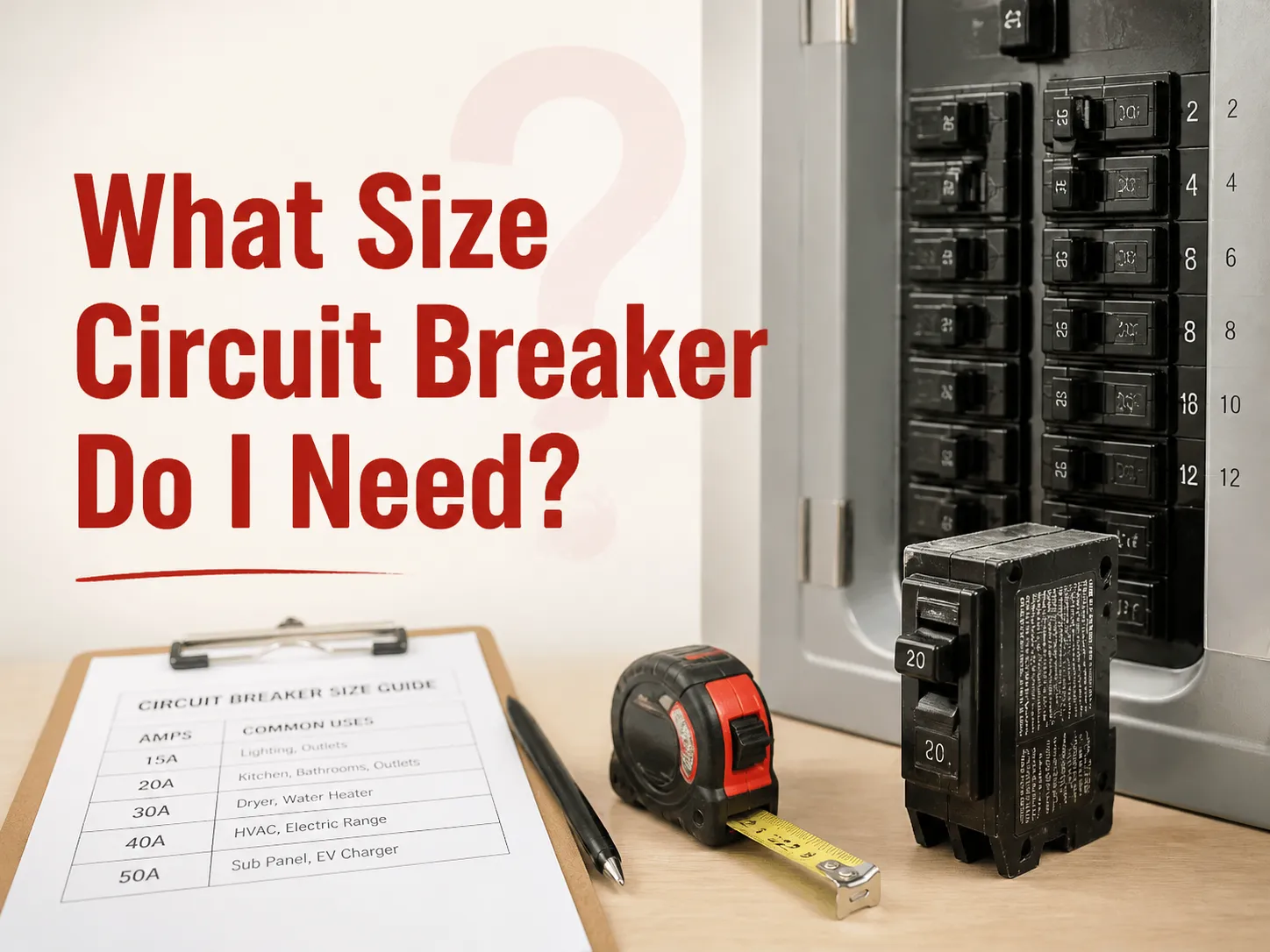
Most online guides falsely state the following: NEC 240.4(D) does not apply to 8 AWG. The small conductor rule pertains to 18, 16, 14, 12, and 10 AWG, and states that the maximum rating is 15 A for the 14 AWG copper, 20 A for the 12 AWG copper, and 30 A for the 10 AWG copper. Because 8 AWG surpasses the limit, the rule in NEC 240.4 applies directly to it, and it is protected by the general rule, where NEC 240.4(B) grants a right to use the next standard overcurrent device size after the ampacity of the wire.
The calculations for 8 AWG copper with the temperature of 75 °C are as follows:
- Ampacity: 50 A.
- Sizes of circuit breakers: 15, 20, 25, 30, 35, 40, 45, 50, 60, 70, 80.
- Next standard size is 45 A, then 50 A. Because the ampacity of the wire is 50 A, one can use a 50 A circuit breaker at 75 °C.
However, there are two constraints. First, because NEC 240.4(D) does not set a limit on the size of 8 AWG wire, it becomes your sole obligation to confirm this or that rating for the amperage of the circuit breaker, so you have to be confident in your calculation. Besides, NEC 240.4(B) is not suitable for multioutlet power circuits, so 50 A circuit breaker at 8 AWG is forbidden under this condition.
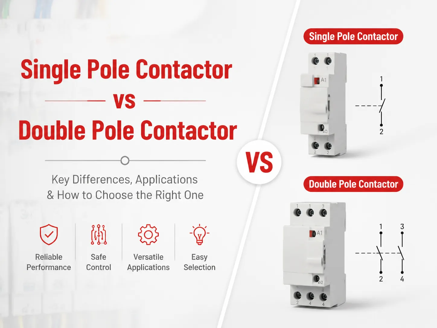
If you need to have the circuit of 60 A, there is no way to use 8 AWG copper for that. Where the breaker sits in a two-pole configuration and how that affects the rest of the circuit is a separate question, and the differences are laid out in this comparison of 50 amp single-pole and double-pole breakers.
Derating: When 8 AWG Stops Being Enough
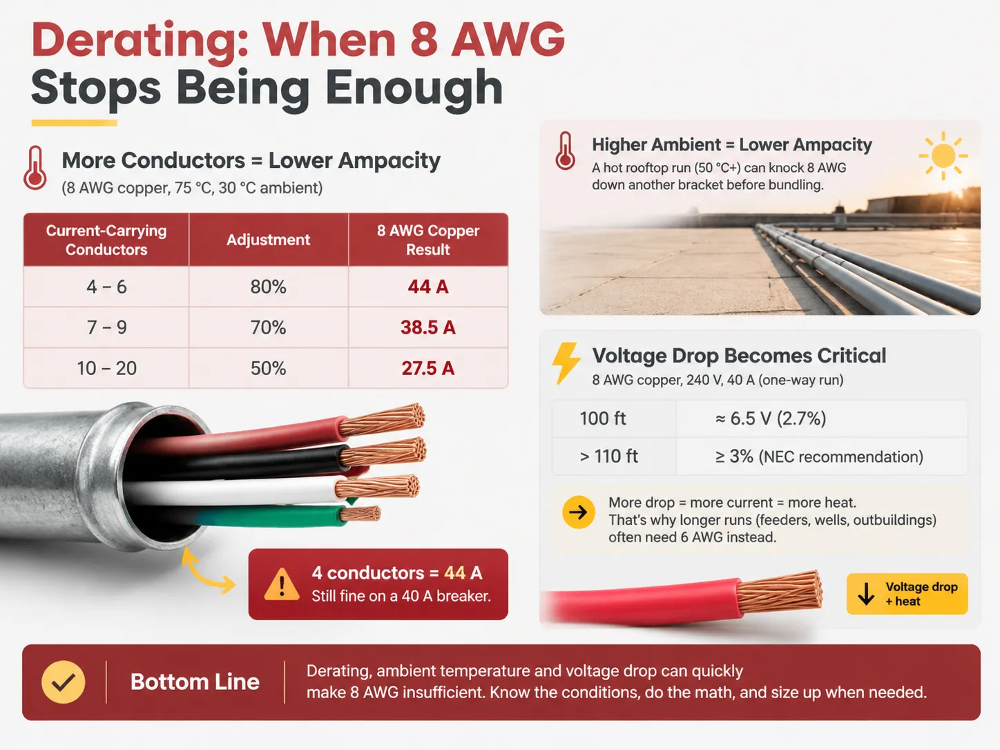
The table prescribes only a maximum of three current-carrying conductors and 30 °C of ambient temperature, but both assumptions are usually inaccurate. At 8 AWG, this creates an immediate problem, as no small conductor backstop will save you.
| Condição | Adjustment | 8 AWG copper result |
|---|---|---|
| 4–6 current-carrying conductors | 80% | 55 A × 0.80 = 44 A |
| 7–9 current-carrying conductors | 70% | 55 A × 0.70 = 38.5 A |
| 10–20 current-carrying conductors | 50% | 55 A × 0.50 = 27.5 A |
For example, when looking at the first row of the table, if we run four wires of 8 AWG THHN copper through one PVC conduit, we get derated ampacity of 44 A. If we then compare this with the terminal value of ampacity at 75°C which is 50 A, we get 44 A, which means we are fine with our 40 A breaker. If we keep adding conductors to bring the count to seven, the derated ampacity drops to 38.5 A. At this stage, we cannot use 8 AWG wire any longer and we need to switch to 6 AWG wire.
Ambient temperature adds to the problem. The ampacities of wires are determined under the assumption of ambient temperature of 30 C. Under the hotter conditions, correction factors come into play. If we have a conduit running on the roof in hot climate, it gets real hot, around 50 C, and even before we account for the factors of bundling this brings our 8 AWG ampacity down another notch. Finally, if we have continuous load amounting to 125% of the wire’s capacity, we are likely to end up with disappointed numbers on the end of our calculations.
Voltage Drop: The Constraint That Stops Being Theoretical
It is at 8 AWG that one should start to refer to voltage drop as a determining factor when selecting the wire size rather than confirm it. For example, stranded 8 AWG copper has a DC resistance of roughly 0.628 Ω/1000 ft when the temperature is 75 °C. AC resistance is even higher.
Now, a 240 V circuit carrying 40 A would provide the following values: with 100 ft run in one direction, the voltage drop would be approximately 6.5 V or around 2.7%. So, anywhere from 110 ft onward you will face the NEC’s allowed maximum since the 3% limit for branch circuits is highly recommended.
3% and 5% limits are recommendations that are not legally enforced, but recommendations are there for a reason. If the voltage reaches 5%, due to this under-voltage a motor would draw more current than with the normal voltage leading to potential heating of wires. It is usually the case that the most often used 8 AWG circuit would require more powerful wires to cope with the distance. Sizing a feeder for a large service makes the trade-off concrete in the same way, as this guide to wire sizing for a 100 amp service shows.
What 8 AWG Is Actually Used For
The uses of the material are derived from the ratings. 8 AWG copper wire allows for carrying currents within the range of 40–50 A according to known applications, including:
- Feeders for subpanels. The 8/3 cable connecting the subpanel drawing a current of 40 or 50 A in the garage, for instance, provided the sum of the load and the connection distance do not exceed the limits;
- AC and heat pump units. Many central air conditioning units require maximum protection against overcurrent being equal to 40/50 A;
- Electric powered water heaters. Tank water heaters having a power of 9 kW and working at 240 volts may be equipped with heaters using 8/2 wire and a breaker rated at 40 A.
- Cooktops and wall ovens. Relatively small separated units may be powered by 8 AWG cables, however, many ovens require the use of 6 AWG wire nowadays.
- Generators and transfer switches. The 8/3 SOOW portable generator cable supplies a 50 A inlet box;
- Electric charging for EV vehicles. A regular 8 AWG job is represented by a charger rated for 32 A and using a 40 A breaker.
- Solar PV circuits. This circuit must meet the requirements of the NEC Article 690, where 8 AWG THHN or PV types of wire for wire runs suitable for source and output are widely used.
Note that most of these circuits are circuits dedicated to a single unit of load rather than multi-outlet circuits, which is not accidental. The reason for the difference in application is that a dedicated circuit has only one known load, thus allowing for the definite answer for derating and terminal issues. Multi-outlet circuits, on the contrary, do not lead to such definite answer because the reason for the difference is that the two types of circuits are treated differently by electrical code.
Grounding Conductor and Cable Configurations
The equipment grounding conductor is determined by the rating of the overcurrent device rather than the ungrounded conductors. For a circuit rated at 40 or 50 A, table 250.122 advises a 10 AWG copper wire. The wire does not have to correspond to the wire size of the hot wires, and therefore, it is unnecessary to oversize the grounding conductor simply because the hot conductors are bigger.
| Configuração | Conductors | Uso típico |
|---|---|---|
| 8/2 | Hot, neutral, ground | Water heater, 240 V load with no neutral requirement |
| 8/3 | Two hots, neutral, ground | Subpanel feed, 120/240 V mixed loads, generator inlet |
| 8/4 | Three hots, neutral, ground or four conductors for three-phase work | Three-phase equipment and specialized feeders |
The figure that follows the slash indicates the quantity of conductors carrying the current, rather than the grounding conductor. As a result, the number of wires used in an 8/2 cable is three. Knowing whether the load will require a neutral conductor is vital when determining the cable configuration for that subpanel, for this will determine whether it will work for 120-volt circuits or not at all.
A Five-Step Method for Any 8 AWG Job
- Determine the lowest rating of terminals in the circuit. The options are the label of the breaker, the listing of the panelboard, and the nameplate of the appliance. This becomes the column to use.
- Then you have to identify the kind of the cable or conductor. If any of these types is NM-B, it means the current drops to the 60 degrees Celsius column despite the terminals’ ratings.
- Then proceed with the 90-degree Celsius value for derating. It equals 55 amperes for copper and 45 amperes for aluminum. Also, don’t forget to apply the correction factors, including conductor-count and ambient temperature correction factors.
- Choose the minimal value among the derated value and the terminals value, and that is the real ampacity.
- Now determine the size of the breaker based on that value by selecting the smallest size mentioned in 240.4(B), remembering that 240.4(D) doesn’t apply to 8 AWG and 240.4(B) does not apply to the multi-outlet receptacle circuits.
Make sure you check the voltage drop over the actual length of the run and upsize if the wire needs to be improved. If something changes in the point number five, then the wire should be recalculated, while the calculations will stay the same.
FAQ
How many amps can an 8 AWG handle?
An 8 AWG copper wire is capable of carrying an electrical current of 40 A for a temperature of 60°C, 50 A for a temperature of 75°C, and 55 A for a temperature of 90°C according to NEC Table 310.16. An 8 AWG aluminum wire will carry 30 A for a temperature of 60°C, 40 A for 75°C, and 45 A for 90°C, but it will not carry the highest possible current for the three given temperatures. The limiting factor in those instances is the lowest current considering the termination method, material of cable, and derating values; in practical applications, this value is usually around 40 A when NM-B aluminum cable is used and approximately 50 A when utilizing conduit installation operating at 75°C.
Is 8 AWG good for 40 amps?
Indeed, this is a prudent decision. Copper’s rating at a temperature of 60 degrees Celsius is an important factor in the use of NM-B cable regarding compliance, which in the case of an 8 AWG copper NM-B circuit powered by a 40 amp breaker is guaranteed. Mostly, this is how various domestic HVAC equipment are rated.
Will 8 AWG carry 60 amps?
When handling standard installations, an 8 AWG copper wire will not carry more than 55 A even at the temperature of 90 °C, and so that number applies to the derating of the wire, rather than its terminal capacity. To get a current of 60 A, a wire of 6 AWG will be needed, with a terminal capacity of 65 A at 75 °C. Therefore, the claim that 8 AWG is able to carry a current of 60 A is based on the wrong column Read or best ignores 110.14(C).
Will 8 AWG handle 50 amps?
This is true in cases where termination ratings are 75 °C and the conductor is not NM-B. Table 310.16 indicates that the rating is 50 A at 75 °C for 8 AWG copper, which corresponds to the standard overcurrent device rating. Since 8 AWG is larger than the limit specified in the small conductor rule found in 240.4(D), it is allowed to use the 50 A circuit breaker according to 240.4(B) as long as this is not a multi-outlet branch circuit supplying receptacles. Always check the breaker and panel markings before using them.
Referências
- NFPA — NFPA 70 National Electrical Code, Tables 310.16, 250.122 and 310.15(C)(1), and Sections 110.14(C), 240.4 and 690.8
- Southwire — conductor ampacity, resistance and cable construction data for building wire
- EC&M Magazine — ampacity adjustment, correction factor and terminal temperature guidance
- International Association of Electrical Inspectors — code interpretation on conductor sizing and overcurrent protection
- NEMA — building wire and cable standards, and terminal temperature rating practice
- Grainger — current US pricing and specification data for 8 AWG building wire and cable assemblies
- Eaton — circuit breaker terminal ratings and panelboard termination specifications
- US Department of Energy — residential wiring and electrical load guidance
Conclusão
The 8 AWG wire caters for three ampacity ratings, as it is subject to three thermal insulation, meaning that the ampacity rating to use is determined by the weakest termination used in the circuit, and the wire type. When using copper, the ampacity ratings will be 40 A at 60 C, 50 A at 75 C and 55 A at 90 C while with aluminum wire, the ratings are 30 A at 60 C, 40 A at 75 C and 45 A at 90 C, which means that the amperage rating of 8 AWG wire used in NM-B cable is 40 A, while for the wiring done with conduits is 50 A at 75 degree terminations. One has first to check the terminal ratings before dealing with the ampacity of the wire run, so that one has to repeat the following three steps one after another.