Se você acabou de comprar uma nova unidade de ar condicionado, um carregador de veículo elétrico ou um forno comercial, seu técnico pode pedir a ampacidade mínima do circuito disponível na placa de identificação. Nesse momento, você pode se deparar com um número que parece não fazer sentido para você. Se você cometer um erro, pode acabar usando um fio subdimensionado (e assim – pode superaquecer, causar disparos indesejados e talvez um incêndio), ou pode gastar muito dinheiro ao usar um fio superdimensionado.
Neste guia, você aprenderá o que significa a ampacidade mínima do circuito, como ela é calculada, qual é a diferença entre ampacidade mínima do circuito e dimensionamento do disjuntor e como transformar essa ampacidade mínima do circuito no tamanho correto do fio — obedecendo às normas NEC no processo.
Em palavras simples, MCA ou Ampacidade Mínima do Circuito é a capacidade mínima de um fio necessária para operar corretamente um dispositivo. Para calculá-la, use a regra 125% do NEC, que implica multiplicar a maior carga contínua, ou seja, a maior corrente de carga total do motor, por 1,25, juntamente com todas as outras cargas. Depois disso, deve-se escolher o menor fio que atenda ou exceda esse requisito conforme a Tabela 310.16 do NEC.
O que é Ampacidade Mínima do Circuito?
A Ampacidade Mínima do Circuito é o menor valor calculado expresso em amperes que indica a ampacidade mínima de um condutor de circuito necessária para alimentar uma carga sem superaquecer. MCA não representa a quantidade de corrente que o equipamento realmente consumiria em uso normal. Em vez disso, é um requisito mínimo derivado do código para garantir que haja uma margem de segurança para operação contínua do circuito e para a corrente de surto de partida.
Na prática, você encontrará a MCA nas placas de identificação de sistemas HVAC, bombas de calor, unidades de refrigeração comercial, aquecedores de água, carregadores para veículos elétricos e na maioria dos dispositivos que envolvem motores e elementos de aquecimento. Os fabricantes devem incluí-la para cumprir o código que determina ser obrigatório considerar o tamanho adequado do fio com a margem adequada. Além disso, somente o fabricante conhece as combinações de pior caso de como as cargas operam.
O ponto mais importante é que você deve cumprir a MCA exigida do condutor. Por exemplo, se a placa de identificação indicar o valor da MCA como 26,4 A, então o fio deve ter uma classificação não inferior a esse nível (ou seja, cumprir esse nível após ser ajustado de acordo com os fatores de desclassificação).
MCA vs FLA vs RLA vs MOCP: A Tabela de Terminologia
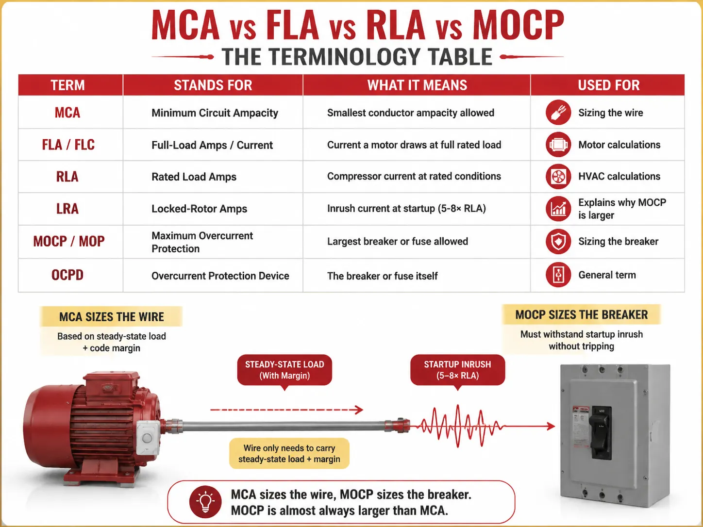
Metade da confusão em torno da MCA vem da sopa de letras ao lado dela na placa de identificação. Aqui está o que cada termo realmente significa:
| Termo | Significado | O que significa | Usado para |
|---|---|---|---|
| MCA | Ampacidade Mínima do Circuito | Menor ampacidade do condutor permitida | Dimensionamento do fio |
| FLA / FLC | Amperes de Carga Total / Corrente | Corrente que um motor consome na carga total nominal | Cálculos de motor |
| RLA | Amperes de Carga Nominal | Corrente do compressor em condições nominais | Cálculos HVAC |
| LRA | Amperes de Rotor Bloqueado | Corrente de surto na partida (5-8× RLA) | Explica por que o MOCP é maior |
| MOCP / MOP | Proteção máxima contra sobrecorrente | Maior disjuntor ou fusível permitido | Dimensionamento do disjuntor |
| OCPD | Dispositivo de Proteção contra Sobrecorrente | O próprio disjuntor ou fusível | Termo geral |
O principal componente do modelo mental é levar em consideração dois parâmetros diferentes envolvidos neste cálculo — MCA e MOCP, que não são os mesmos valores — o primeiro é tipicamente menor que o segundo porque o disjuntor deve suportar o pico de corrente quando o equipamento é ligado, enquanto o fio suporta o fluxo contínuo de corrente mais seus fatores definidos pelos códigos.
A Regra 125% Explicada
A regra 125% está na base de todo cálculo para MCA. Ela pode ser encontrada em várias seções do NEC e, em cada uma delas, o objetivo é fornecer uma margem de segurança especificada em caso de cargas contínuas ou cargas que são ligadas com a corrente de surto.
- NEC 210.19(A)(1) — circuitos derivados: os fios devem ter a ampacidade mínima de 125% da carga contínua, e 100% da carga não contínua. Uma carga é considerada “carga contínua” se a carga em questão opera em valor total por 3 horas ou mais (definição NEC 100).
- NEC 215.2 — alimentadores: o mesmo requisito 125% também é aplicável aos alimentadores.
- NEC 430.22 — um motor: os fios devem ser calculados com base em 125% do FLA do motor.
- NEC 440.22 / prática do fabricante — HVAC: MCA = 125% do RLA para o maior motor.
Por que 125%? Existem duas razões para isso. Primeiramente, sem calor contínuo: quando um fio transporta sua corrente nominal por um longo período, ele aquece até sua temperatura máxima. O extra 25% significa que o isolamento permanece frio. Em segundo lugar, ao ligar qualquer motor operando em modo regular, ele consome muitas vezes mais corrente do que durante a operação real do motor.
Como Calcular MCA (Com Exemplos Práticos)
Para motores individuais (seguindo o código NEC 430.22),
MCA = FLA do motor × 1,25
Por exemplo, se houver um motor monofásico de 3 HP, 230V com FLA de 17 A, então,
MCA = 17 × 1,25 = 21,25 A. Agora, de acordo com a tabela NEC 310.16 (coluna 75 °C), pode-se inferir que o fio menor que pode suportar esse valor de 21,25 A é o 12 AWG, que é classificado para 25 A de capacidade de condução de corrente.
Para o sistema de carga múltipla (NEC 430.24),
MCA = (maior FLA do motor × 1,25) + todos os outros SLAs dos motores
| Carga | FLA (Amperes) | Multiplicador | Contribuição |
|---|---|---|---|
| Maior motor (10 HP, 460V) | 14.0 | ×1.25 | 17,5 A |
| Segundo motor (5 HP) | 7.6 | ×1.00 | 7,6 A |
| Terceiro motor (2 HP) | 3.4 | ×1.00 | 3,4 A |
| MCA total | 28,5 A | ||
Para 28,5A, NEC 310.16 (75°C) indica que o menor tamanho adequado é fio de cobre 10 AWG (35A) — 12 AWG (25A) seria muito pequeno.
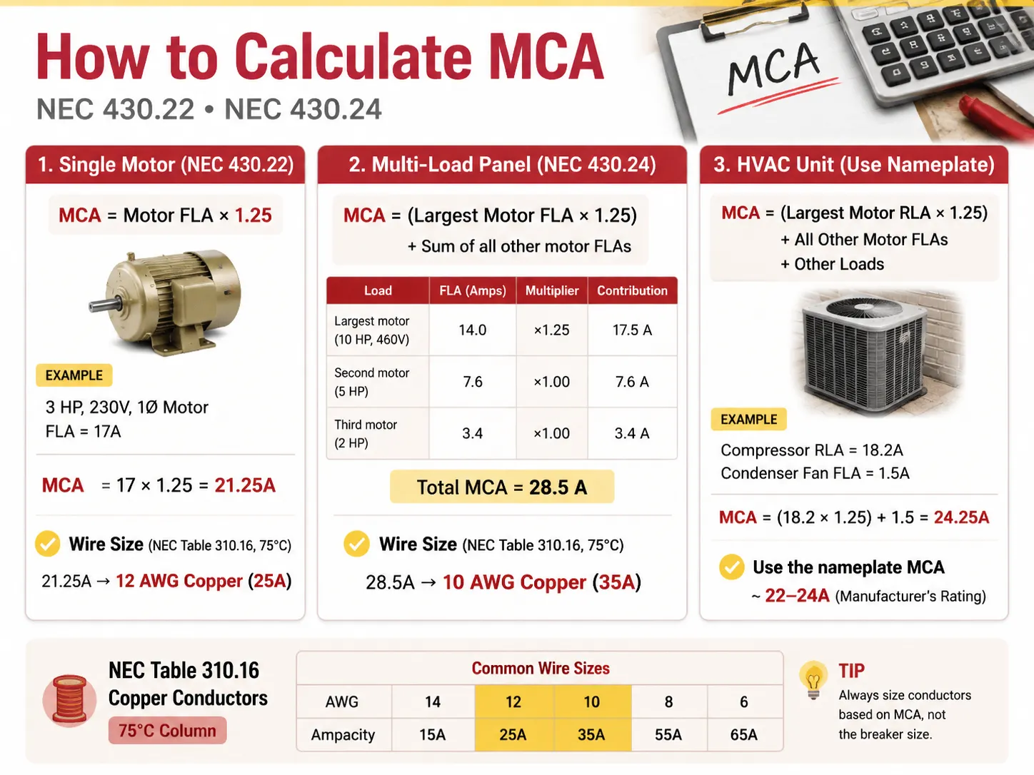
No caso de uma unidade HVAC com compressor e motor de ventilador, os valores ideais de RLA seriam os seguintes: MCA = (RLA do maior motor × 1,25) + FLAs dos outros motores + outras cargas.
Por exemplo, se o compressor tem RLA de 18,2 Amperes e o ventilador do condensador tem FLA de 1,5 Amperes, então temos o seguinte: MCA = (18,2 × 1,25) + 1,5 = 24,25 Amperes.
Por favor, tenha em mente que este valor é arredondado pelo fabricante para um padrão mais comum de 22-24 Amperes, na placa de identificação da unidade HVAC.
MCA vs Proteção Máxima contra Sobrecorrente (MOCP)
É aqui que os DIYers frequentemente erram: eles pensam que o disjuntor precisa corresponder ao MCA. Não precisa. O disjuntor é classificado de acordo com o MOCP, que é diferente do número na placa de identificação.
| Fator | MCA (Fio) | MOCP (Disjuntor) |
|---|---|---|
| O que dimensiona | Condutor (fio) | Dispositivo de proteção contra sobrecorrente (disjuntor/fusível) |
| Relação típica | Número menor | Número maior (deve permitir a corrente de partida) |
| Protege contra | Sobreaquecimento da isolação | Curto-circuito e falha à terra |
| Regra | Ampacidade do fio ≥ MCA | Tamanho do disjuntor ≤ MOCP (segundo tamanhos padrão NEC 240.6) |
| Unidade exemplo | MCA 26,4A | MOCP 45A |
Neste caso, fio de cobre AWG 10 (30-35A de ampacidade) é usado para alimentar a unidade e é protegido contra surtos por um disjuntor de 45A. Isso é permitido — ter um disjuntor com classificação maior que o fio? É permitido segundo NEC 440.22(a) porque o compressor possui seus próprios mecanismos de proteção. Portanto, neste caso, apenas a proteção contra surtos é exigida do disjuntor. Isso se aplica tanto a sistemas de motor quanto HVAC, com exceção dos sistemas de fiação regulares, onde o disjuntor deve ter uma classificação inferior à dos fios.
Como Escolher o Tamanho Correto do Fio AWG
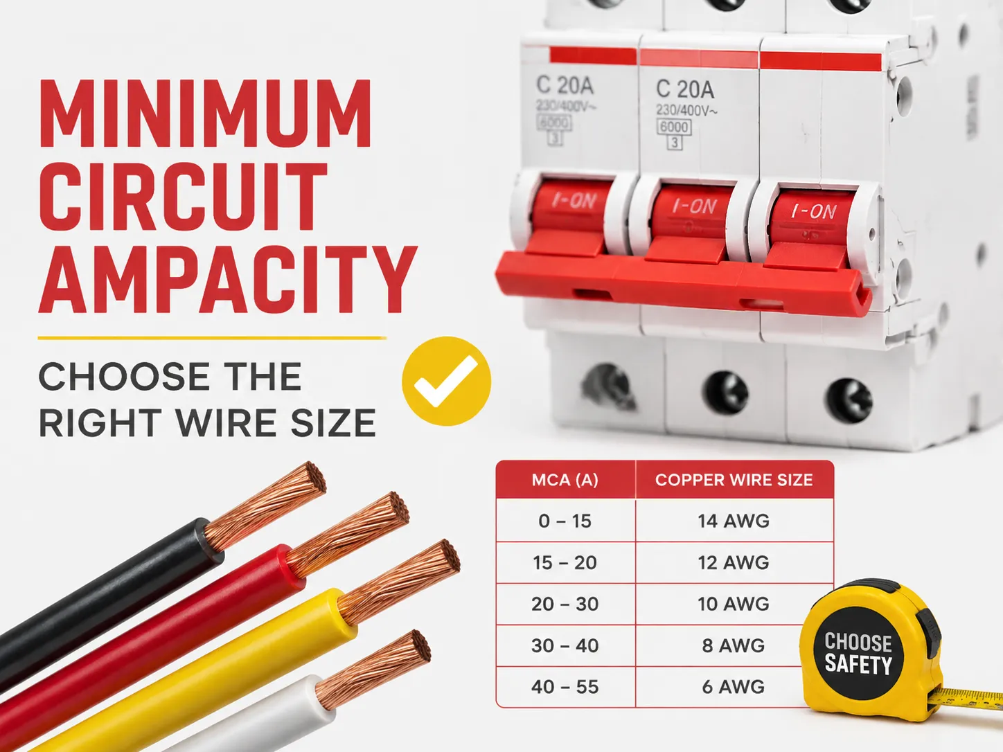
Quando você tem o MCA, selecionar o fio é simplesmente consultar a Tabela 310.16 do NEC. Consulte a coluna 75°C ao usar cobre THHN/THWN-2 (que é o fio padrão para eletrodutos), ou se usar NM-B (Romex) ou fiação de instalações antigas, consulte a coluna 60°C.
| Tamanho do Fio de Cobre (AWG) | Ampacidade @ 60°C | Capacidade de corrente @ 75°C | Cobre MCA Até | Disjuntor Típico |
|---|---|---|---|---|
| 14 AWG | 15 A | 20 A | 15-20 A | 15 A |
| 12 AWG | 20 A | 25 A | 20-25 A | 20 A |
| 10 AWG | 30 A | 35 A | 30-35 A | 30 A |
| 8 AWG | 40 A | 50 A | 40-50 A | 40 A |
| 6 AWG | 55 A | 65 A | 55-65 A | 60 A |
| 4 AWG | 70 A | 85 A | 70-85 A | 80 A |
| 2 AWG | 95 A | 115 A | 95-115 A | 100 A |
| 1/0 AWG | 125 A | 150 A | 125-150 A | 150 A |
| 2/0 AWG | 145 A | 175 A | 145-175 A | 175 A |
| 3/0 AWG | 165 A | 200 A | 165-200 A | 200 A |
Choose the smallest wire whose ampacity is at least equal to the rated ampacity (after derating, which is explained below). For a rated ampacity of 24.25A, the smallest wire that may be used is 12 AWG (25A). However, many installers go to a bigger wire, such as 10 AWG, to accommodate long runs and/or future needs.
200-Amp Service: Can You Use 1/0 Wire?
This question is often asked with regards to residential service upgrades, and the answer is that, with regards to 200A full service, it is a quaint but false no. Keeping in mind the 75°C, the 1/0 copper would have a maximum rating of 150A, and won’t be capable of handling a 200A service load according to the law. If there is a need to achieve 200A residential service, it requires using one of the following types of copper or aluminum wires:
- 2/0 copper which can handle 175A with the temperature of 75°C. This wire is allowed for 200A in some areas (with Special Commercial Code A).
- 3/0 copper which will successfully handle a load of 200A at 75°C.
- 4/0 aluminum wire capable of feeding 180A at 75°C often used in service entrance lines requiring wiring of 200A.
Another variant is to use 1/0 copper wire, which is suitable for use only in case of 150A service lines, and charging 150A sub-panel only. Avoid using 1/0 wire with a 200A service line at all costs since it heats too much when processed for a long time. In addition, make sure to verify with local wiring code and inspector since there are many ambiguities in the NEC 310.12 Service Entrance.
The 80% Rule for Circuit Breakers
NEC 210.20(A) and 215.3 rules say that a circuit breaker should not be loaded for more than 80% of its rating. For example:
- A 15A breaker should handle a continuous load of only 12A.
- A 20A breaker should handle a continuous load of only 16A.
- A 30A breaker should carry a continuous load of only 24A.
- A 100A breaker should bear a full-load of only 80A.
Provide comparisons between all the above examples. The principle behind the regulation is the same in both cases: 80% and 125% factor are identical in their essence claiming that maximum load should not be higher than the rated capacity of the device and can be expressed in a particular order (1/1.25=0.8). For instance, if the device is used with a continuous load of 16A, the conductor should withstand 16*1.25=20A; thus, the particular breaker needs to be rated for a 20A load, and in fact, is rated at only 20A. When you need to match protection devices to a new circuit, a certified miniature circuit breaker range rated for the job — like the HUYU HUM18 MCB series covering 1P to 4P and B/C/D curves — makes the wire-to-breaker match straightforward for panel builders and contractors.
Temperature & Conduit-Fill Derating
The ampacity table base its assumption on 30 degrees Celsius (86 degrees Fahrenheit) ambient temperature, with no conduction of more than 3 wires through a conduit. When the temperature deviates, you have to derate (lower) the ampacity of the wire before comparing it with the MCA.
- High ambient temperature: According to Table 310.15(B)(1) of NEC, correction factors can be used. For example, the current-carrying capacity of a conductor rated for 75°C becomes 22A because at an ambient temperature of 40°C it is multiplied by 0.88.
- Conduit fill: In most cases, the Table 310.15(C)(1) of NEC indicates different correction factors according to the number of wires through the conduit. Thus, for 4-6 conductors, the correction factor is 0.80; for 7-9 conductors, it is 0.70; and for 10-20 it is equal to 0.50. Thus, the bigger number of wires leads to a more considerable heat amount trapped in the conduit.
- Norm: after the derating condition, the new ampacity must be no less than the MCA.
Voltage Drop on Long Runs
In most U.S. locations, voltage drop isn’t a code requirement (excluding a few applications) but is still useful and smart: the branch circuit voltage drop must be 3% and the voltage drop for the whole feeder + branch must equal 5%. A good guideline is when the distance is more than 50 to 100 feet, you have to go one size higher. So for a 120-volt circuit run more than 150 feet, you need to use a bigger wire size even if the MCA table says that you can use 12 AWG (10 AWG will do a better job). Using the wrong sized wire over longer distances results in dim lights, slow motors, and overheating.
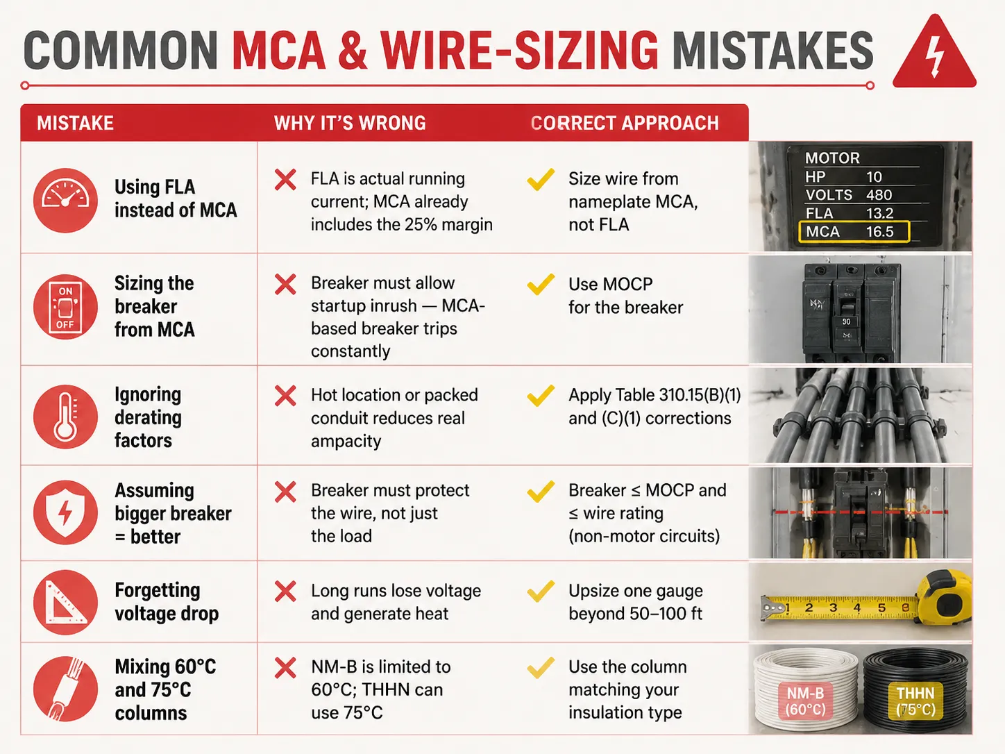
Common MCA & Wire-Sizing Mistakes
| Erro | Por Que Está Errado | Abordagem Correta |
|---|---|---|
| Using FLA instead of MCA | FLA is actual running current; MCA already includes the 25% margin | Size wire from nameplate MCA, not FLA |
| Sizing the breaker from MCA | Breaker must allow startup inrush — MCA-based breaker trips constantly | Use MOCP for the breaker |
| Ignoring derating factors | Hot location or packed conduit reduces real ampacity | Apply Table 310.15(B)(1) and (C)(1) corrections |
| Assuming bigger breaker = better | Breaker must protect the wire, not just the load | Breaker ≤ MOCP and ≤ wire rating (non-motor circuits) |
| Forgetting voltage drop | Long runs lose voltage and generate heat | Upsize one gauge beyond 50-100 ft |
| Mixing 60°C and 75°C columns | NM-B is limited to 60°C; THHN can use 75°C | Use the column matching your insulation type |
Typical MCA Values for Common Equipment
| Equipamento | Typical MCA | Wire Size (75°C copper) | MOCP / Breaker |
|---|---|---|---|
| 3 HP 230V motor | ~21.3 A | 12 AWG | 30 A |
| 5 HP 230V motor | ~26.3 A | 10 AWG | 40 A |
| 10 HP 460V motor | ~17.5 A | 12 AWG | 25-30 A |
| 3.5-ton heat pump | ~22-26 A | 10 AWG | 30-45 A |
| 5-ton AC unit | ~30-35 A | 8 AWG | 45-60 A |
| Level 2 EV charger (48A) | ~60 A | 6 AWG | 60 A |
| Electric water heater (4500W/240V) | ~23.4 A | 10 AWG | 30 A |
| 200A residential service | N/A | 2/0-3/0 copper or 4/0 aluminum | 200 A main |
These are general figures — you should regularly refer to the nameplate of your unit. Also, when you are designing or enlarging your distribution installation, ensuring that the protection devices suit the cables is the kind of issue which certified equipment produced by a manufacturer ensuring the whole range addresses: understanding what a 15-amp circuit can actually carry is a good starting point, and for replacement decisions our guide on como saber se um disjuntor está ruim covers the inspection side of the story.
Perguntas Frequentes
What is the 125 rule for breakers?
According to the 125% rule (NEC 210.19, 215.2, 430.22), conductors must be sized at 125% of the continuous load, or 125% of the motor’s full-load amps. In the case of the breaker, it can be seen that the same philosophy is entailed in the 80% rule, meaning that the breaker can only sustain 80% of its rating over time. Both are used to prevent overheating of the insulation. One example would be the case when the continuous load of 20A requires conductors of 25A rating (12 AWG) and a breaker rated 25A or 30A, while only 20A is used continuously in the circuit.
Can I use 1/0 wire for 200 amp service?
1/0 copper can carry 150A current at 75° C. Thus, 1/0 copper is not an appropriate option for 200A power. The right options include either 2/0 copper, good for 175A, or 3/0 copper of 200A. 4/0 aluminum can also be considered as it is good for 180A. In the case of a power of less than 150A, 1/0 copper can be successfully used. Consult a local inspector as NEC 310.12 states that service entrance has its own exceptions.
Will a 100 amp breaker accept 1/0 wire?
In most cases, if the terminal of the breaker is okay for it, then yes—most of the terminals for 100A breakers can take a wire sized up to 2/0 copper or 4/0 aluminum. However, a 100A breaker does not need a wire gauge of 1/0; the only determining thing is the load as it is what tells us what wire size to use in this instance; as an example, when the load is only 70A, then 4 AWG (85A) is the right size. It is important to read the information given on the terminals of the breaker because it is what offers all the necessary information.
What is the 80% rule for circuit breakers?
The 80% rule (NEC 210.20(A), 215.3) indicates that a breaker is limited to carrying 80% of its rating for continuous loads. For example, a 15A breaker has a continuous current maximum of 12A, whereas a 20A breaker can carry 16A and a 100A breaker can carry 80A. There is a balance in the safety margin because it mirrors the 125% rule of current rating in conductors. The full breaker rating can be used for non-continuous loads since they do not follow this rule.
Referências
- NFPA 70 — National Electrical Code (NEC), Articles 210, 215, 240, 310, 430, 440
- OSHA 1910.303 — Electrical Systems: General Requirements
- Mike Holt — NEC Code Change Explanations (125% / 80% rules)
- EC&M Magazine — Conductor Sizing and MCA/MOCP Applications
- ENERGY STAR — HVAC Installation and Circuit Sizing Guidance
- NEMA — Motor and Electrical Product Standards
Conclusão
Minimum circuit ampacity provides the lowest size of wire that can be used for different types of equipment. The number is calculated based on the 125% rule by taking the largest current load or motor load multiplied by 1.25 and adding other loads to get the calculation. The wire size is determined by the MCA but the size of the breaker is determined by a separate number called MOCP. Be aware of applicable features such as the 80% rule for continuous loads, derating for heat as well as conduit fill, and voltage drop on long runs to avoid the problems of underused wires as well as wasted copper. And when a replacement breaker or panel upgrade is part of the job, understanding breaker replacement costs and the differences between protection devices like MCBs and MCCBs helps you plan the whole circuit — not just the wire.