Если вы только что приобрели новый кондиционер, зарядное устройство для электромобиля или коммерческую печь, ваш техник может попросить минимальную амперажную нагрузку цепи (MCA), указанную на шильдике. В этот момент вы можете увидеть число, которое кажется вам бессмысленным. Если вы ошибетесь, вы можете либо использовать провод с недостаточным сечением (что может привести к перегреву, ложным срабатываниям и даже пожару), либо потратить слишком много денег на провод с избыточным сечением.
В этом руководстве вы узнаете, что означает минимальная амперажная нагрузка цепи, как она рассчитывается, в чем разница между минимальной амперажной нагрузкой цепи и подбором автоматического выключателя, а также как преобразовать эту минимальную амперажную нагрузку в правильный размер провода — соблюдая при этом требования NEC.
Проще говоря, MCA или минимальная амперажная нагрузка цепи — это минимальная пропускная способность провода, необходимая для правильной работы устройства. Для ее расчета используйте правило NEC 125%, которое предполагает умножение наибольшей непрерывной нагрузки, то есть максимального тока полной нагрузки двигателя, на 1,25 вместе со всеми остальными нагрузками. После этого выбирается самый маленький провод, который соответствует или превышает это требование согласно таблице NEC 310.16.
Что такое минимальная амперажная нагрузка цепи?
Минимальная амперажная нагрузка цепи — это наименьшее рассчитанное значение, выраженное в амперах, которое показывает минимальную пропускную способность проводника цепи, необходимую для подачи нагрузки без перегрева. MCA не показывает фактический ток, который оборудование будет потреблять в нормальных условиях. Вместо этого это минимальное требование, выведенное из кода, чтобы обеспечить запас безопасности для непрерывной работы цепи и пускового тока.
На практике вы найдете MCA на шильдиках систем HVAC, тепловых насосов, коммерческих холодильных установок, водонагревателей, зарядных устройств для электромобилей и большинства устройств с двигателями и нагревательными элементами. Производители обязаны указывать его для соблюдения кода, который требует учета правильного размера провода с соответствующим запасом. Кроме того, только производитель знает наихудшие комбинации работы нагрузок.
Самое важное — соблюдать требуемое MCA проводника. Например, если на шильдике указано значение MCA 26,4 А, то провод должен иметь номинал не менее этого значения (то есть соответствовать этому уровню после корректировки с учетом коэффициентов снижения).
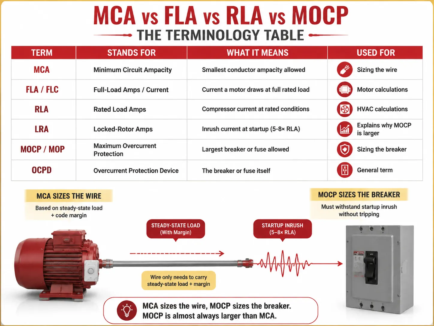
MCA против FLA против RLA против MOCP: таблица терминов
Половина путаницы вокруг MCA возникает из-за аббревиатур рядом с ним на шильдике. Вот что на самом деле означает каждый термин:
| Термин | Обозначает | Что означает | Используется для |
|---|---|---|---|
| MCA | Минимальная амперажная нагрузка цепи | Наименьшая допустимая пропускная способность проводника | Подбор провода |
| МКА | Ток полной нагрузки | Ток, который двигатель потребляет при полной номинальной нагрузке | Расчеты двигателя |
| FLA / FLC | Номинальный ток нагрузки | Ток компрессора при номинальных условиях | Расчеты HVAC |
| ФЛА / ФЛК | Ток блокировки ротора | Пусковой ток при запуске (5-8× RLA) | Объясняет, почему MOCP больше |
| МОКП / МОП | Максимальная защита от перегрузки по току | Самый большой разрешённый автоматический выключатель или предохранитель | Подбор автоматического выключателя |
| ОКРЛ | Устройство защиты от перегрузки по току | Сам автоматический выключатель или предохранитель | Общий термин |
Основным элементом ментального моделирования является учёт двух различных параметров, участвующих в этом расчёте — MCA и MOCP, которые не совпадают — первый обычно меньше второго, поскольку автоматический выключатель должен выдерживать скачок тока при запуске оборудования, в то время как проводник обеспечивает прохождение постоянного тока с учётом факторов, установленных нормативами.
Объяснение правила 125%
Правило 125% лежит в основе каждого расчёта MCA. Оно встречается в различных разделах NEC, и в каждом из них цель — обеспечить заданный запас безопасности для нагрузок, работающих непрерывно, или нагрузок, включаемых с пусковым током.
- NEC 210.19(A)(1) — ответвительные цепи: провода должны иметь минимальную амперажность 125% от непрерывной нагрузки и 100% от непостоянной нагрузки. Нагрузка считается “непрерывной”, если она работает на полной мощности 3 часа и более (определение NEC 100).
- NEC 215.2 — питающие линии: то же требование 125% применяется и к питающим линиям.
- NEC 430.22 — один мотор: провода должны рассчитываться исходя из 125% от FLA мотора.
- NEC 440.22 / практика производителя — HVAC: MCA = 125% от RLA для самого крупного мотора.
Почему 125%? Есть две причины. Во-первых, отсутствие непрерывного нагрева: когда провод длительное время пропускает номинальный ток, он нагревается до максимальной температуры. Дополнительные 25% означают, что изоляция остаётся прохладной. Во-вторых, при запуске любой мотор в рабочем режиме потребляет ток, многократно превышающий ток при нормальной работе.
Как рассчитать MCA (с примерами)
Для отдельных моторов (согласно коду NEC 430.22),
MCA = FLA мотора × 1.25
Например, если есть однофазный мотор 3 HP, 230 В с FLA 17 А, тогда,
MCA = 17 × 1.25 = 21.25 А. Согласно таблице NEC 310.16 (столбец 75 °C), можно сделать вывод, что минимальный провод, способный выдержать 21.25 А, — это 12 AWG, рассчитанный на ток 25 А.
Для системы с несколькими нагрузками (NEC 430.24),
MCA = (наибольший FLA двигателя × 1,25) + все остальные SLA двигателей
| Нагрузка | FLA (Амперы) | Множитель | Вклад |
|---|---|---|---|
| Наибольший двигатель (10 л.с., 460В) | 14.0 | ×1.25 | 17,5 А |
| Второй двигатель (5 л.с.) | 7.6 | ×1.00 | 7,6 А |
| Третий двигатель (2 л.с.) | 3.4 | ×1.00 | 3,4 А |
| Общий MCA | 28,5 А | ||
Для 28,5А, NEC 310.16 (75°C) указывает, что минимальный подходящий размер — медный провод 10 AWG (35А) — 12 AWG (25А) будет слишком мал.
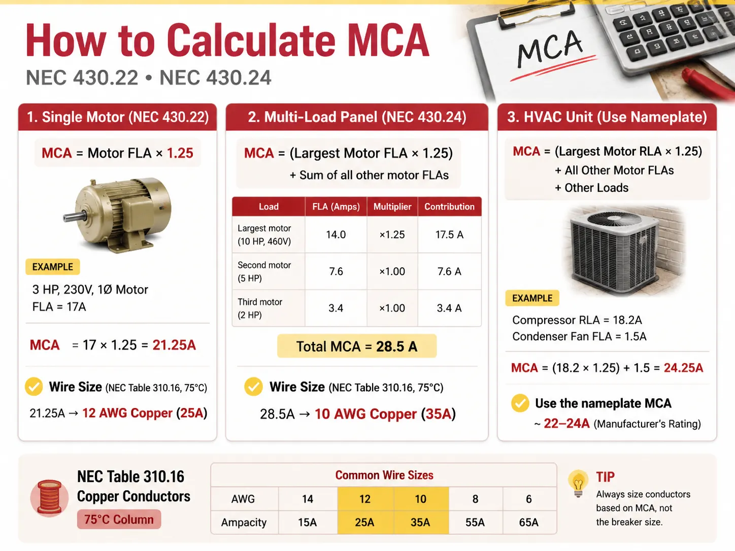
В случае HVAC-установки с компрессором и вентиляторным двигателем идеальные значения RLA будут следующими: MCA = (RLA наибольшего двигателя × 1,25) + FLA других двигателей + другие нагрузки.
Например, если у компрессора RLA 18,2 Ампера, а у вентилятора конденсатора FLA 1,5 Ампера, тогда: MCA = (18,2 × 1,25) + 1,5 = 24,25 Ампера.
Обратите внимание, что это значение округлено производителем до более стандартного 22-24 Ампер на табличке HVAC-установки.
MCA против Максимальной защиты от перегрузки по току (MOCP)
Здесь часто ошибаются непрофессионалы: они думают, что автомат должен соответствовать MCA. Это не так. Автомат рассчитан согласно MOCP, который отличается от значения на табличке.
| Фактор | MCA (Провод) | MOCP (Автомат) |
|---|---|---|
| Что он определяет | Проводник (провод) | Устройство защиты от перегрузки (автомат/предохранитель) |
| Типичная взаимосвязь | Меньшее число | Большее число (должно учитывать пусковой ток) |
| Защищает от | Перегрев изоляции | Короткое замыкание и замыкание на землю |
| Правило | Токопроводимость провода ≥ MCA | Размер автомата ≤ MOCP (по стандартным размерам NEC 240.6) |
| Пример устройства | MCA 26,4А | MOCP 45А |
В этом случае для питания устройства используется медный провод 10 AWG (токопроводимость 30-35А), защищённый автоматом на 45А. Разрешено ли иметь автомат с номиналом выше, чем у провода? Это допускается согласно NEC 440.22(a), поскольку компрессор имеет собственные защитные механизмы. Следовательно, в данном случае автомат обеспечивает только защиту от перегрузок. Это применимо как к двигателям, так и к HVAC-системам, за исключением обычных проводных систем, где автомат должен иметь номинал ниже, чем у проводов.
Как выбрать правильный размер провода AWG
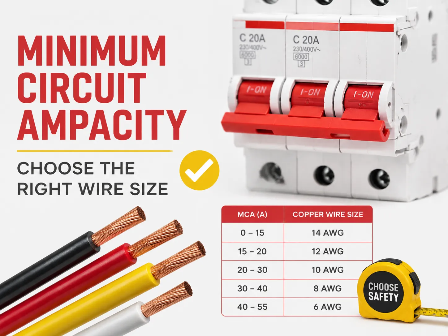
Имея MCA, выбор провода сводится к таблице NEC 310.16. Используйте колонку 75°C при применении медного провода THHN/THWN-2 (стандартный провод для труб), или при использовании NM-B (Romex) или для старых установок — колонку 60°C.
| Размер медного провода (AWG) | Токопроводимость при 60°C | Ампераж при 75°C | Покрывает MCA до | Типичный автомат |
|---|---|---|---|---|
| 14 AWG | 15 А | 20 A | 15-20 А | 15 А |
| 12 AWG | 20 A | 25 A | 20-25 А | 20 A |
| 10 AWG | 30 A | 35 A | 30-35 А | 30 A |
| 8 AWG | 40 А | 50 A | 40-50 А | 40 А |
| 6 AWG | 55 А | 65 A | 55-65 А | 60 А |
| 4 AWG | 70 А | 85 A | 70-85 А | 80 А |
| 2 AWG | 95 А | 115 A | 95-115 А | 100 A |
| 1/0 AWG | 125 А | 150 А | 125-150 А | 150 А |
| 2/0 AWG | 145 А | 175 А | 145-175 А | 175 А |
| 3/0 AWG | 165 А | 200 А | 165-200 А | 200 А |
Выберите самый маленький провод, номинальная токовая нагрузка которого как минимум равна номинальной токовой нагрузке (после понижения, что объясняется ниже). Для номинальной токовой нагрузки 24,25 А самым маленьким проводом, который можно использовать, является 12 AWG (25 А). Однако многие монтажники выбирают провод большего сечения, например 10 AWG, чтобы учесть длинные участки и/или будущие потребности.
Обслуживание на 200 ампер: можно ли использовать провод 1/0?
Этот вопрос часто задают в связи с обновлением жилых сервисов, и ответ таков: в отношении полного обслуживания на 200 А это устаревшее, но неверное «нет». Учитывая 75°C, медный провод 1/0 имеет максимальный рейтинг 150 А и не сможет выдержать нагрузку 200 А согласно нормативам. Если необходимо обеспечить жилое обслуживание на 200 А, требуется использовать один из следующих типов медных или алюминиевых проводов:
- Медный провод 2/0, который может выдерживать 175 А при температуре 75°C. Этот провод разрешён для 200 А в некоторых регионах (с особым коммерческим кодом A).
- Медный провод 3/0, который успешно выдержит нагрузку 200 А при 75°C.
- Алюминиевый провод 4/0, способный подавать 180 А при 75°C, часто используется в линиях ввода обслуживания, требующих проводки на 200 А.
Другой вариант — использовать медный провод 1/0, который подходит только для линий обслуживания на 150 А и подключения подпанелей на 150 А. Избегайте использования провода 1/0 с линией обслуживания на 200 А, так как он сильно нагревается при длительной эксплуатации. Кроме того, обязательно проверьте местные нормы проводки и инспектора, так как в NEC 310.12 Service Entrance существует множество неоднозначностей.
Правило 80% для автоматических выключателей
Правила NEC 210.20(A) и 215.3 гласят, что автоматический выключатель не должен загружаться более чем на 80% от своего номинала. Например:
- Автоматический выключатель на 15 А должен выдерживать непрерывную нагрузку только 12 А.
- Автоматический выключатель на 20 А должен выдерживать непрерывную нагрузку только 16 А.
- Автоматический выключатель на 30 А должен нести непрерывную нагрузку только 24 А.
- Автоматический выключатель на 100 А должен выдерживать полную нагрузку только 80 А.
Проведите сравнения между всеми приведёнными примерами. Принцип регулирования одинаков в обоих случаях: коэффициенты 80% и 125% по сути идентичны, утверждая, что максимальная нагрузка не должна превышать номинальную ёмкость устройства и может быть выражена в определённом порядке (1/1,25=0,8). Например, если устройство используется с непрерывной нагрузкой 16 А, проводник должен выдерживать 16*1,25=20 А; следовательно, конкретный автоматический выключатель должен быть рассчитан на нагрузку 20 А и фактически имеет номинал только 20 А. При необходимости подобрать защитные устройства для новой цепи, сертифицированный ряд миниатюрных автоматических выключателей, рассчитанных на эту задачу — например, серия HUYU HUM18 MCB охватывающая 1P до 4P и кривые B/C/D — упрощает подбор провода к автомату для сборщиков щитов и подрядчиков.
Понижение номинала из-за температуры и заполнения трубопровода
Таблица ампеража основывается на предположении о температуре окружающей среды 30 градусов Цельсия (86 градусов Фаренгейта) и отсутствии прохождения более 3 проводов через одну трубу. При отклонении температуры необходимо понизить (дерейтировать) ампераж провода перед сравнением с MCA.
- Высокая температура окружающей среды: согласно Таблице 310.15(B)(1) NEC, могут применяться корректирующие коэффициенты. Например, токовая нагрузка проводника с номиналом 75°C становится 22А, так как при температуре окружающей среды 40°C она умножается на 0,88.
- Заполнение трубы: в большинстве случаев Таблица 310.15(C)(1) NEC указывает различные корректирующие коэффициенты в зависимости от количества проводов в трубе. Так, для 4-6 проводников коэффициент равен 0,80; для 7-9 проводников — 0,70; для 10-20 — 0,50. Таким образом, большее количество проводов приводит к большему количеству тепла, задерживаемого в трубе.
- Норма: после применения условий дерейтинга новый ампераж должен быть не меньше MCA.
Падение напряжения на длинных участках
В большинстве регионов США падение напряжения не является требованием коду (за исключением некоторых применений), но это полезно и разумно: падение напряжения в ответвительной цепи должно быть не более 3%, а падение напряжения для всей линии питания + ответвления — не более 5%. Хорошее правило — при расстоянии более 50-100 футов использовать провод большего сечения. Например, для цепи 120 В с длиной более 150 футов необходимо использовать провод большего сечения, даже если таблица MCA допускает использование 12 AWG (лучше использовать 10 AWG). Использование провода неправильного сечения на больших расстояниях приводит к тусклому освещению, замедленной работе двигателей и перегреву.
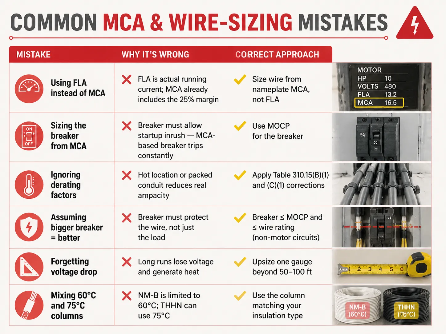
Распространённые ошибки при определении MCA и выборе сечения провода
| Ошибка | Почему это неправильно | Правильный подход |
|---|---|---|
| Использование FLA вместо MCA | FLA — это фактический рабочий ток; MCA уже включает запас 25%. | Выбирать сечение провода по MCA с таблички, а не по FLA. |
| Выбор автоматического выключателя по MCA | Выключатель должен допускать пусковой ток — выключатель, выбранный по MCA, срабатывает постоянно. | Использовать MOCP для выбора выключателя. |
| Игнорирование факторов дерейтинга | Высокая температура или заполненная труба уменьшают реальный ампераж. | Применять корректировки из Таблиц 310.15(B)(1) и (C)(1). |
| Предположение, что больший выключатель — лучше | Выключатель должен защищать провод, а не только нагрузку. | Выключатель ≤ MOCP и ≤ номинала провода (для цепей без двигателей). |
| Забвение о падении напряжения. | Long runs lose voltage and generate heat | Upsize one gauge beyond 50-100 ft |
| Mixing 60°C and 75°C columns | NM-B is limited to 60°C; THHN can use 75°C | Use the column matching your insulation type |
Typical MCA Values for Common Equipment
| Equipment | Typical MCA | Wire Size (75°C copper) | MOCP / Breaker |
|---|---|---|---|
| 3 HP 230V motor | ~21.3 A | 12 AWG | 30 A |
| 5 HP 230V motor | ~26.3 A | 10 AWG | 40 А |
| 10 HP 460V motor | ~17.5 A | 12 AWG | 25-30 A |
| 3.5-ton heat pump | ~22-26 A | 10 AWG | 30-45 A |
| 5-ton AC unit | ~30-35 A | 8 AWG | 45-60 A |
| Level 2 EV charger (48A) | ~60 A | 6 AWG | 60 А |
| Electric water heater (4500W/240V) | ~23.4 A | 10 AWG | 30 A |
| 200A residential service | Н/Д | 2/0-3/0 copper or 4/0 aluminum | 200 A main |
These are general figures — you should regularly refer to the nameplate of your unit. Also, when you are designing or enlarging your distribution installation, ensuring that the protection devices suit the cables is the kind of issue which certified equipment produced by a manufacturer ensuring the whole range addresses: understanding what a 15-amp circuit can actually carry is a good starting point, and for replacement decisions our guide on том, как определить, что автомат неисправен covers the inspection side of the story.
Часто задаваемые вопросы
What is the 125 rule for breakers?
According to the 125% rule (NEC 210.19, 215.2, 430.22), conductors must be sized at 125% of the continuous load, or 125% of the motor’s full-load amps. In the case of the breaker, it can be seen that the same philosophy is entailed in the 80% rule, meaning that the breaker can only sustain 80% of its rating over time. Both are used to prevent overheating of the insulation. One example would be the case when the continuous load of 20A requires conductors of 25A rating (12 AWG) and a breaker rated 25A or 30A, while only 20A is used continuously in the circuit.
Can I use 1/0 wire for 200 amp service?
1/0 copper can carry 150A current at 75° C. Thus, 1/0 copper is not an appropriate option for 200A power. The right options include either 2/0 copper, good for 175A, or 3/0 copper of 200A. 4/0 aluminum can also be considered as it is good for 180A. In the case of a power of less than 150A, 1/0 copper can be successfully used. Consult a local inspector as NEC 310.12 states that service entrance has its own exceptions.
Will a 100 amp breaker accept 1/0 wire?
In most cases, if the terminal of the breaker is okay for it, then yes—most of the terminals for 100A breakers can take a wire sized up to 2/0 copper or 4/0 aluminum. However, a 100A breaker does not need a wire gauge of 1/0; the only determining thing is the load as it is what tells us what wire size to use in this instance; as an example, when the load is only 70A, then 4 AWG (85A) is the right size. It is important to read the information given on the terminals of the breaker because it is what offers all the necessary information.
What is the 80% rule for circuit breakers?
The 80% rule (NEC 210.20(A), 215.3) indicates that a breaker is limited to carrying 80% of its rating for continuous loads. For example, a 15A breaker has a continuous current maximum of 12A, whereas a 20A breaker can carry 16A and a 100A breaker can carry 80A. There is a balance in the safety margin because it mirrors the 125% rule of current rating in conductors. The full breaker rating can be used for non-continuous loads since they do not follow this rule.
Ссылки
- NFPA 70 — National Electrical Code (NEC), Articles 210, 215, 240, 310, 430, 440
- OSHA 1910.303 — Electrical Systems: General Requirements
- Mike Holt — NEC Code Change Explanations (125% / 80% rules)
- EC&M Magazine — Conductor Sizing and MCA/MOCP Applications
- ENERGY STAR — HVAC Installation and Circuit Sizing Guidance
- NEMA — Motor and Electrical Product Standards
Заключение
Minimum circuit ampacity provides the lowest size of wire that can be used for different types of equipment. The number is calculated based on the 125% rule by taking the largest current load or motor load multiplied by 1.25 and adding other loads to get the calculation. The wire size is determined by the MCA but the size of the breaker is determined by a separate number called MOCP. Be aware of applicable features such as the 80% rule for continuous loads, derating for heat as well as conduit fill, and voltage drop on long runs to avoid the problems of underused wires as well as wasted copper. And when a replacement breaker or panel upgrade is part of the job, understanding breaker replacement costs and the differences between protection devices like MCBs and MCCBs helps you plan the whole circuit — not just the wire.