Si acaba de comprar una nueva unidad de aire acondicionado, un cargador para vehículo eléctrico o un horno comercial, su técnico podría solicitar la ampacidad mínima del circuito disponible en la placa de características. En ese momento, podría encontrarse mirando un número que le parece sin sentido. Si comete un error, puede terminar usando un cable que puede ser de tamaño insuficiente (y por lo tanto, puede sobrecalentarse, causar disparos intempestivos y tal vez un incendio), o puede gastar demasiado dinero en cableado con un cable sobredimensionado.
En esta guía, aprenderá qué significa la ampacidad mínima del circuito, cómo se calcula, cuál es la diferencia entre la ampacidad mínima del circuito y el dimensionamiento del interruptor, y cómo convertir esta ampacidad mínima del circuito en el tamaño correcto del cable, cumpliendo con las normativas NEC en el proceso.
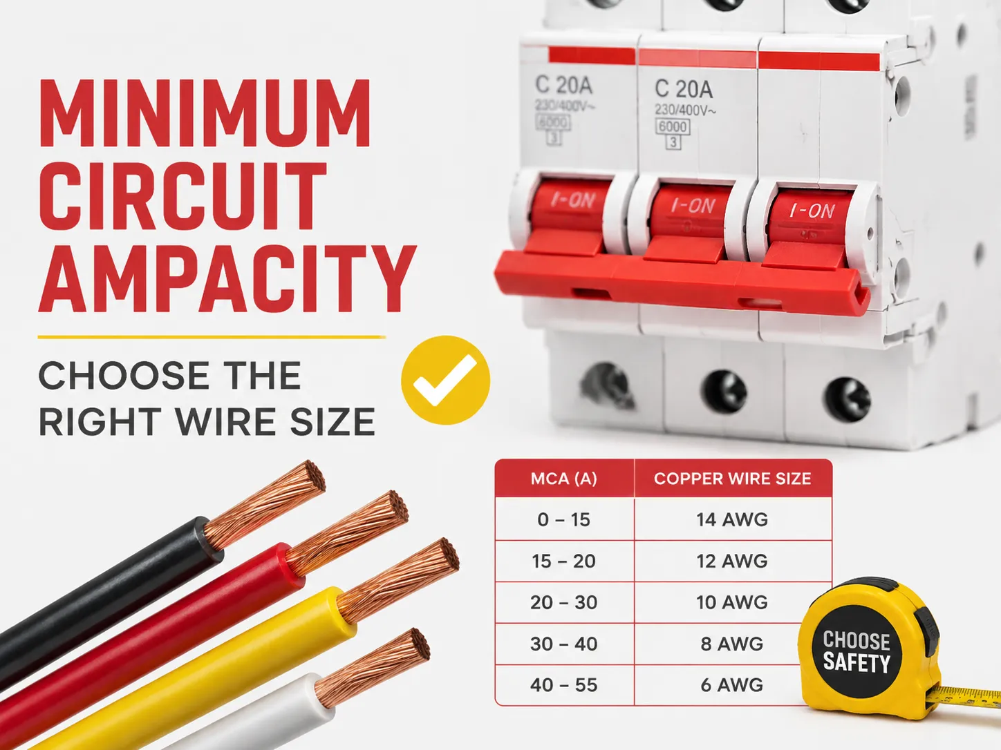
En palabras simples, MCA o Ampacidad Mínima del Circuito es la capacidad mínima de un cable necesaria para operar correctamente un dispositivo. Para calcularla, use la regla 125% del NEC, que implica multiplicar la carga continua más grande, es decir, la corriente nominal completa del motor más grande, por 1.25, junto con todas las demás cargas. Después de eso, se debe elegir el cable más pequeño que cumpla o supere este requisito según la Tabla 310.16 del NEC.
¿Qué es la Ampacidad Mínima del Circuito?
La Ampacidad Mínima del Circuito es el valor calculado más pequeño expresado en amperios que muestra la ampacidad mínima de un conductor de circuito necesaria para suministrar una carga sin sobrecalentamiento. MCA no representa la cantidad de corriente que el equipo realmente consumiría en uso normal. En cambio, es un requisito mínimo derivado del código para asegurar que exista un margen de seguridad para la operación continua del circuito y para la corriente de arranque.
En la práctica, encontrará la MCA en las placas de características de sistemas HVAC, bombas de calor, unidades de refrigeración comercial, calentadores de agua, cargadores para vehículos eléctricos y la mayoría de los dispositivos que involucran motores y elementos calefactores. Los fabricantes deben incluirla para cumplir con el código que establece que es obligatorio considerar el tamaño adecuado del cable con el margen adecuado. Además, solo un productor conoce las combinaciones en el peor de los casos de cómo operan las cargas.
El punto más importante es que debe cumplir con la MCA requerida del conductor. Por ejemplo, si la placa de características indica un valor de MCA de 26.4 A, entonces el cable debe tener una clasificación no menor a este nivel (es decir, cumplir con este nivel después de ser ajustado según los factores de reducción).
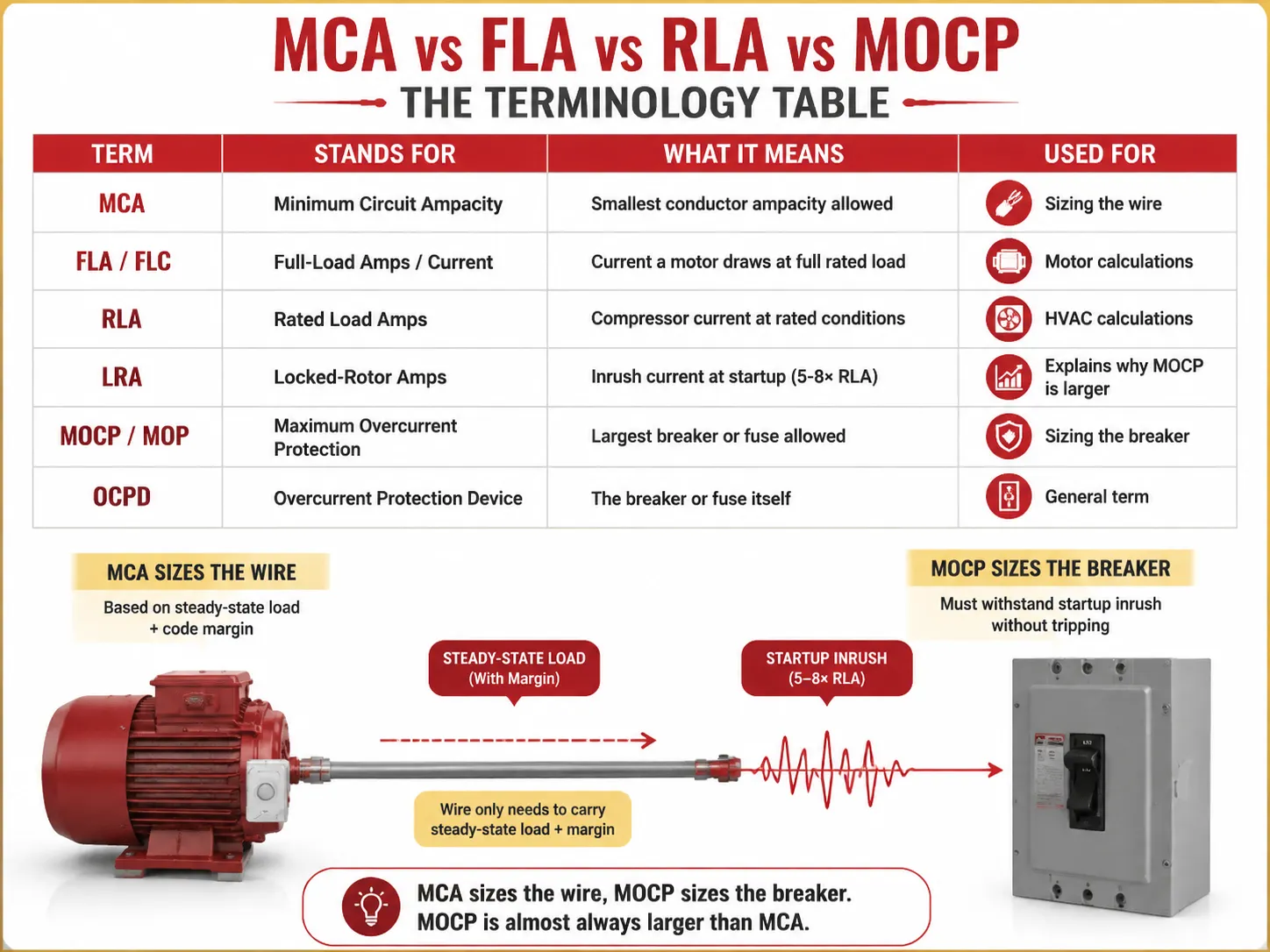
MCA vs FLA vs RLA vs MOCP: La Tabla de Terminología
La mitad de la confusión alrededor de la MCA proviene de la sopa de letras que aparece junto a ella en la placa de características. Aquí está lo que realmente significa cada término:
| Término | Significa | Qué significa | Usado para |
|---|---|---|---|
| MCA | Ampacidad Mínima del Circuito | La ampacidad mínima permitida del conductor | Dimensionamiento del cable |
| FLA / FLC | Amperios / Corriente a plena carga | Corriente que un motor consume a carga nominal completa | Cálculos de motor |
| RLA | Amperios de carga nominal | Corriente del compresor en condiciones nominales | Cálculos HVAC |
| LRA | Amperios de rotor bloqueado | Corriente de irrupción al arrancar (5-8× RLA) | Explica por qué MOCP es mayor |
| MOCP / MOP | Protección máxima contra sobrecorriente | El interruptor o fusible más grande permitido | Dimensionamiento del interruptor |
| OCPD | Dispositivo de protección contra sobrecorriente | El interruptor o fusible en sí | Término general |
El componente principal del modelado mental es tener en cuenta dos parámetros diferentes involucrados en este cálculo — MCA y MOCP, que no son las mismas cifras — el primero suele ser menor que el segundo porque el interruptor debe soportar el pico de corriente cuando se inicia el equipo mientras que el cable se encarga del flujo continuo de corriente más sus factores establecidos por los códigos.
Explicación de la regla 125%
La regla 125% está en la base de cada cálculo para MCA. Se puede encontrar en varias secciones del NEC y, en cada una de ellas, el objetivo es proporcionar un margen de seguridad especificado en caso de cargas continuas o cargas que se encienden con la corriente de irrupción.
- NEC 210.19(A)(1) — circuitos derivados: los cables deben tener una capacidad mínima de 125% de la carga continua, y 100% de la carga no continua. Se considera “carga continua” aquella que opera a su valor completo durante 3 horas o más (definición NEC 100).
- NEC 215.2 — alimentadores: el mismo requisito de 125% también es aplicable a los alimentadores.
- NEC 430.22 — un motor: los cables deben calcularse basándose en 125% de la FLA del motor.
- NEC 440.22 / práctica del fabricante — HVAC: MCA = 125% del RLA para el motor más grande.
¿Por qué 125%? Hay dos razones para ello. Primero, no hay calor continuo: cuando un cable transporta su corriente nominal durante un largo período se calienta hasta su temperatura máxima. El extra 25% significa que el aislamiento permanece frío. Segundo, al arrancar, cualquier motor que opere en modo normal consume muchas veces más corriente que durante la operación real del motor.
Cómo calcular MCA (con ejemplos prácticos)
Para motores individuales (siguiendo el código NEC 430.22),
MCA = FLA del motor × 1.25
Por ejemplo, si hay un motor monofásico de 3 HP, 230 V con FLA de 17 A, entonces,
MCA = 17 × 1.25 = 21.25 A. Ahora, según la tabla 310.16 del NEC (columna 75 °C), se puede inferir que el cable pequeño que puede manejar este valor de 21.25 A es 12 AWG, que está clasificado para una capacidad de corriente de 25 A.
Para el sistema de carga múltiple (NEC 430.24),
MCA = (FLA del motor más alto × 1.25) + todas las demás SLA de motores
| Carga | FLA (Amperios) | Multiplicador | Contribución |
|---|---|---|---|
| Motor más grande (10 HP, 460V) | 14.0 | ×1.25 | 5 A |
| Segundo motor (5 HP) | 7.6 | ×1.00 | 6 A |
| Tercer motor (2 HP) | 3.4 | ×1.00 | 4 A |
| MCA total | 5 A | ||
Para 28.5A, NEC 310.16 (75°C) indica que el calibre más pequeño adecuado es cobre 10 AWG (35A) — 12 AWG (25A) sería demasiado pequeño.
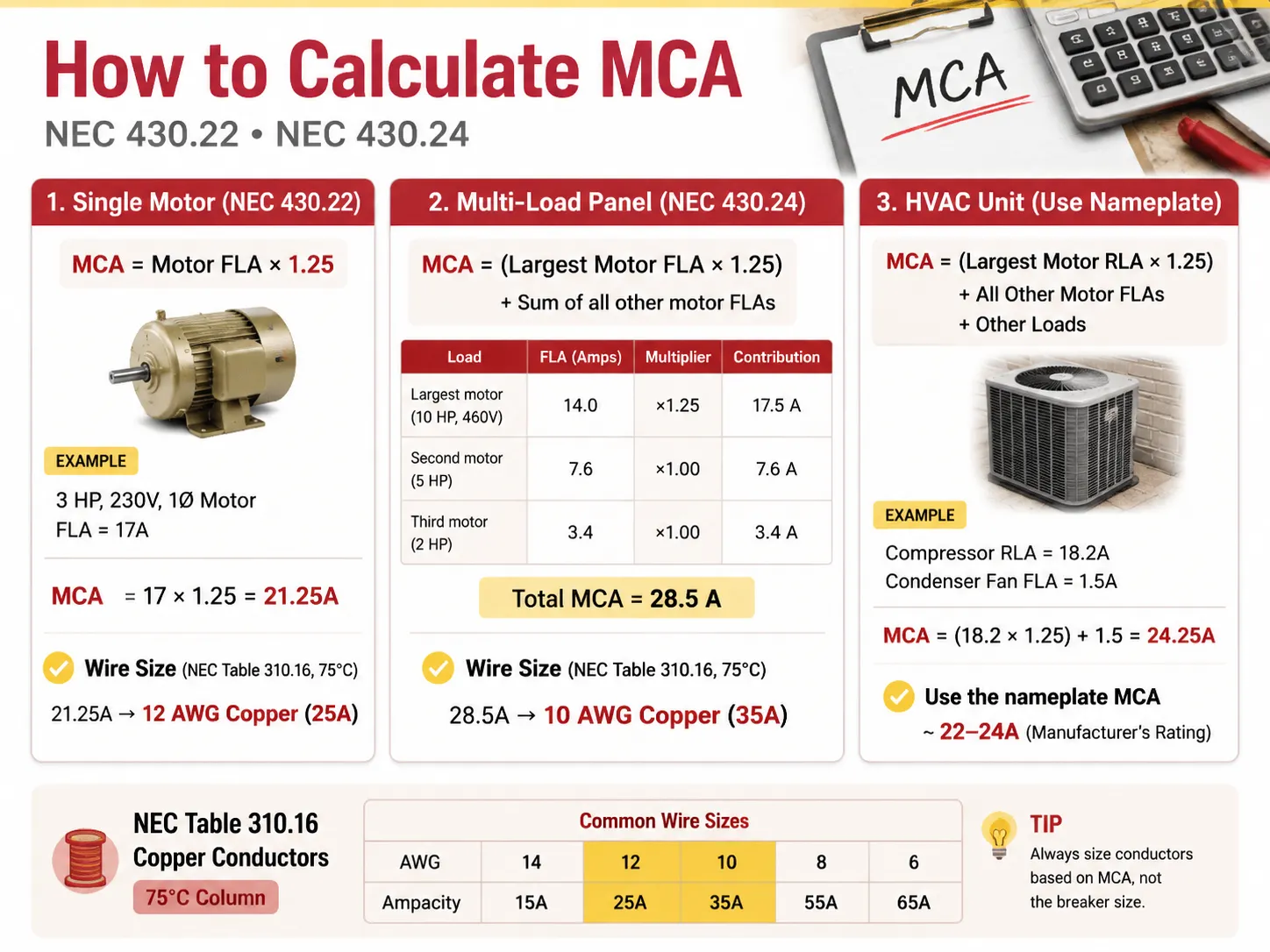
En el caso de una unidad HVAC con un compresor y motor de ventilador, los valores ideales de RLA serían los siguientes: MCA = (RLA del motor más grande × 1.25) + FLA de otros motores + otras cargas.
Por ejemplo, si el compresor tiene un RLA de 18.2 Amperios y el ventilador del condensador tiene un FLA de 1.5 Amperios, entonces tenemos lo siguiente: MCA = (18.2 × 1.25) + 1.5 = 24.25 Amperios.
Tenga en cuenta que este valor es redondeado por el fabricante a un estándar más común de 22-24 Amperios, en la placa de características de la unidad HVAC.
MCA vs Protección Máxima contra Sobrecorriente (MOCP)
Aquí es donde los aficionados suelen equivocarse: piensan que el interruptor debe coincidir con el MCA. No es así. El interruptor está clasificado según el MOCP, que es diferente del número en la placa de características.
| Factor | MCA (Cable) | MOCP (Interruptor) |
|---|---|---|
| Lo que dimensiona | Conductor (cable) | Dispositivo de sobrecorriente (interruptor/fusible) |
| Relación típica | Número menor | Número mayor (debe permitir la corriente de arranque) |
| Protege contra | Sobrecalentamiento del aislamiento | Cortocircuito y falla a tierra |
| Regla | Capacidad de corriente del cable ≥ MCA | Tamaño del interruptor ≤ MOCP (según tamaños estándar NEC 240.6) |
| Unidad de ejemplo | MCA 26.4A | MOCP 45A |
En este caso, se utiliza cable de cobre calibre 10 AWG (30-35A de capacidad) para alimentar la unidad y está protegido contra sobrecargas por un interruptor de 45A. ¿Está permitido tener un interruptor con una clasificación mayor que la del cable? Es permisible bajo NEC 440.22(a) porque el compresor tiene sus propios mecanismos de protección. Por lo tanto, en este caso, solo se requiere protección contra sobrecargas por parte del interruptor. Esto aplica tanto para sistemas de motor como HVAC, con la excepción de los sistemas de cableado regulares, donde un interruptor debe tener una clasificación menor que la de los cables.
Cómo elegir el tamaño correcto de cable AWG
Cuando se tiene MCA, seleccionar el cable es simplemente referirse a la Tabla 310.16 del NEC. Consulte la columna de 75°C cuando use cobre THHN/THWN-2 (que es el cable estándar para conductos), o si usa NM-B (Romex) o cableado de instalaciones antiguas, consulte la columna de 60°C.
| Tamaño de cable de cobre (AWG) | Capacidad de corriente @ 60°C | Capacidad de corriente @ 75°C | Cubre MCA hasta | Interruptor típico |
|---|---|---|---|---|
| 14 AWG | 15 A | 20 A | 15-20 A | 15 A |
| 12 AWG | 20 A | 25 A | 20-25 A | 20 A |
| 10 AWG | 30 A | 35 A | 30-35 A | 30 A |
| 8 AWG | 40 A | 50 A | 40-50 A | 40 A |
| 6 AWG | 55 A | 65 A | 55-65 A | 60 A |
| 4 AWG | 70 A | 85 A | 70-85 A | 80 A |
| 2 AWG | 95 A | 115 A | 95-115 A | 100 A |
| 1/0 AWG | 125 A | 150 A | 125-150 A | 150 A |
| 2/0 AWG | 145 A | 175 A | 145-175 A | 175 A |
| 3/0 AWG | 165 A | 200 A | 165-200 A | 200 A |
Elija el cable más pequeño cuya capacidad de corriente sea al menos igual a la capacidad nominal (después de la reducción, que se explica a continuación). Para una capacidad nominal de 24.25A, el cable más pequeño que se puede usar es 12 AWG (25A). Sin embargo, muchos instaladores optan por un cable más grande, como 10 AWG, para acomodar recorridos largos y/o necesidades futuras.
Servicio de 200 amperios: ¿Se puede usar cable 1/0?
Esta pregunta se plantea a menudo en relación con las actualizaciones de servicio residencial, y la respuesta es que, con respecto a un servicio completo de 200A, es un no pintoresco pero falso. Teniendo en cuenta los 75°C, el cobre 1/0 tendría una clasificación máxima de 150A y no sería capaz de manejar una carga de servicio de 200A según la normativa. Si se necesita lograr un servicio residencial de 200A, se requiere usar uno de los siguientes tipos de cables de cobre o aluminio:
- Cobre 2/0 que puede manejar 175A a una temperatura de 75°C. Este cable está permitido para 200A en algunas áreas (con Código Comercial Especial A).
- Cobre 3/0 que manejará con éxito una carga de 200A a 75°C.
- Cable de aluminio 4/0 capaz de alimentar 180A a 75°C, utilizado frecuentemente en líneas de entrada de servicio que requieren cableado de 200A.
Otra variante es usar cable de cobre 1/0, que es adecuado solo para líneas de servicio de 150A y para alimentar subpaneles de 150A únicamente. Evite usar cable 1/0 con una línea de servicio de 200A a toda costa, ya que se calienta demasiado cuando se procesa durante mucho tiempo. Además, asegúrese de verificar con el código local de cableado y el inspector, ya que existen muchas ambigüedades en el NEC 310.12 Entrada de Servicio.
La regla 80% para interruptores automáticos
Las reglas NEC 210.20(A) y 215.3 establecen que un interruptor automático no debe cargarse con más del 80% de su capacidad nominal. Por ejemplo:
- Un interruptor de 15A debe manejar una carga continua de solo 12A.
- Un interruptor de 20A debe manejar una carga continua de solo 16A.
- Un interruptor de 30A debe soportar una carga continua de solo 24A.
- Un interruptor de 100A debe soportar una carga completa de solo 80A.
Proporcione comparaciones entre todos los ejemplos anteriores. El principio detrás de la regulación es el mismo en ambos casos: el factor 80% y el factor 125% son idénticos en esencia, afirmando que la carga máxima no debe ser superior a la capacidad nominal del dispositivo y puede expresarse en un orden particular (1/1.25=0.8). Por ejemplo, si el dispositivo se usa con una carga continua de 16A, el conductor debe soportar 16*1.25=20A; por lo tanto, el interruptor particular debe estar clasificado para una carga de 20A, y de hecho, está clasificado solo para 20A. Cuando necesita emparejar dispositivos de protección con un nuevo circuito, una gama certificada de interruptores automáticos en miniatura clasificados para el trabajo — como la serie HUYU HUM18 MCB que cubre de 1P a 4P y curvas B/C/D — facilita la correspondencia cable-interruptor para fabricantes de paneles y contratistas.
Reducción por temperatura y llenado de conductos
La tabla de ampacidad basa su suposición en una temperatura ambiente de 30 grados Celsius (86 grados Fahrenheit), sin conducción de más de 3 cables a través de un conducto. Cuando la temperatura varía, debe reducirse (disminuir) la ampacidad del cable antes de compararla con el MCA.
- Alta temperatura ambiente: Según la Tabla 310.15(B)(1) del NEC, se pueden usar factores de corrección. Por ejemplo, la capacidad de corriente de un conductor clasificado para 75°C se convierte en 22A porque a una temperatura ambiente de 40°C se multiplica por 0.88.
- Llenado del conducto: En la mayoría de los casos, la Tabla 310.15(C)(1) del NEC indica diferentes factores de corrección según el número de cables a través del conducto. Así, para 4-6 conductores, el factor de corrección es 0.80; para 7-9 conductores, es 0.70; y para 10-20 es igual a 0.50. Por lo tanto, un mayor número de cables conduce a una mayor cantidad de calor atrapado en el conducto.
- Norma: después de la condición de reducción, la nueva ampacidad no debe ser menor que el MCA.
Caída de voltaje en recorridos largos
En la mayoría de las ubicaciones en EE. UU., la caída de voltaje no es un requisito del código (excluyendo algunas aplicaciones), pero sigue siendo útil e inteligente: la caída de voltaje del circuito derivado debe ser 3% y la caída de voltaje para todo el alimentador + derivado debe ser 5%. Una buena guía es que cuando la distancia es mayor a 50 a 100 pies, debe usarse un tamaño de cable mayor. Por lo tanto, para un circuito de 120 voltios con una longitud mayor a 150 pies, debe usarse un cable de mayor tamaño incluso si la tabla MCA indica que se puede usar 12 AWG (10 AWG hará un mejor trabajo). Usar un cable de tamaño incorrecto en distancias largas resulta en luces tenues, motores lentos y sobrecalentamiento.
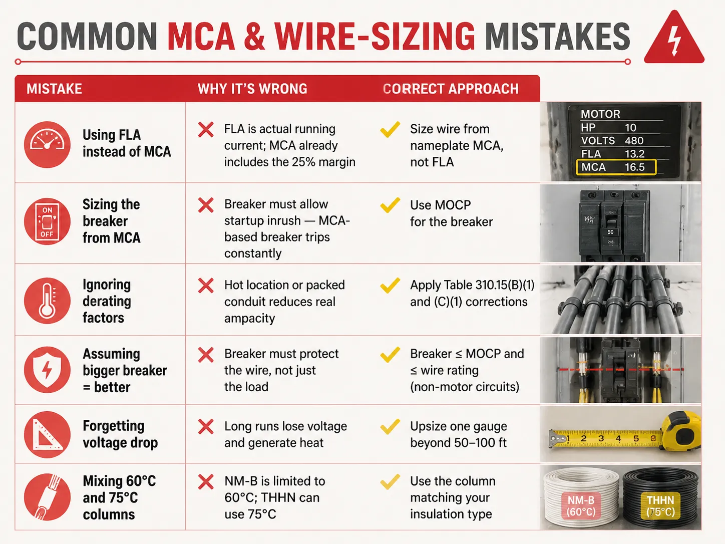
Errores comunes en MCA y dimensionamiento de cables
| Error | Por qué está mal | Enfoque correcto |
|---|---|---|
| Usar FLA en lugar de MCA | FLA es la corriente real de funcionamiento; MCA ya incluye el margen del 25% | Dimensionar el cable a partir del MCA de la placa de características, no del FLA |
| Dimensionar el interruptor a partir del MCA | El interruptor debe permitir la corriente de arranque — un interruptor basado en MCA se dispara constantemente | Usar MOCP para el interruptor |
| Ignorar los factores de reducción | Ubicación caliente o conducto lleno reduce la ampacidad real | Aplicar las correcciones de las Tablas 310.15(B)(1) y (C)(1) |
| Asumir que un interruptor más grande es mejor | El interruptor debe proteger el cable, no solo la carga | Breaker ≤ MOCP and ≤ wire rating (non-motor circuits) |
| Forgetting voltage drop | Long runs lose voltage and generate heat | Upsize one gauge beyond 50-100 ft |
| Mixing 60°C and 75°C columns | NM-B is limited to 60°C; THHN can use 75°C | Use the column matching your insulation type |
Typical MCA Values for Common Equipment
| Equipment | Typical MCA | Wire Size (75°C copper) | MOCP / Breaker |
|---|---|---|---|
| 3 HP 230V motor | ~21.3 A | 12 AWG | 30 A |
| 5 HP 230V motor | ~26.3 A | 10 AWG | 40 A |
| 10 HP 460V motor | ~17.5 A | 12 AWG | 25-30 A |
| 3.5-ton heat pump | ~22-26 A | 10 AWG | 30-45 A |
| 5-ton AC unit | ~30-35 A | 8 AWG | 45-60 A |
| Level 2 EV charger (48A) | ~60 A | 6 AWG | 60 A |
| Electric water heater (4500W/240V) | ~23.4 A | 10 AWG | 30 A |
| 200A residential service | N/A | 2/0-3/0 copper or 4/0 aluminum | 200 A main |
These are general figures — you should regularly refer to the nameplate of your unit. Also, when you are designing or enlarging your distribution installation, ensuring that the protection devices suit the cables is the kind of issue which certified equipment produced by a manufacturer ensuring the whole range addresses: understanding what a 15-amp circuit can actually carry is a good starting point, and for replacement decisions our guide on cómo saber si un interruptor está defectuoso covers the inspection side of the story.
Preguntas Frecuentes
What is the 125 rule for breakers?
According to the 125% rule (NEC 210.19, 215.2, 430.22), conductors must be sized at 125% of the continuous load, or 125% of the motor’s full-load amps. In the case of the breaker, it can be seen that the same philosophy is entailed in the 80% rule, meaning that the breaker can only sustain 80% of its rating over time. Both are used to prevent overheating of the insulation. One example would be the case when the continuous load of 20A requires conductors of 25A rating (12 AWG) and a breaker rated 25A or 30A, while only 20A is used continuously in the circuit.
Can I use 1/0 wire for 200 amp service?
1/0 copper can carry 150A current at 75° C. Thus, 1/0 copper is not an appropriate option for 200A power. The right options include either 2/0 copper, good for 175A, or 3/0 copper of 200A. 4/0 aluminum can also be considered as it is good for 180A. In the case of a power of less than 150A, 1/0 copper can be successfully used. Consult a local inspector as NEC 310.12 states that service entrance has its own exceptions.
Will a 100 amp breaker accept 1/0 wire?
In most cases, if the terminal of the breaker is okay for it, then yes—most of the terminals for 100A breakers can take a wire sized up to 2/0 copper or 4/0 aluminum. However, a 100A breaker does not need a wire gauge of 1/0; the only determining thing is the load as it is what tells us what wire size to use in this instance; as an example, when the load is only 70A, then 4 AWG (85A) is the right size. It is important to read the information given on the terminals of the breaker because it is what offers all the necessary information.
What is the 80% rule for circuit breakers?
The 80% rule (NEC 210.20(A), 215.3) indicates that a breaker is limited to carrying 80% of its rating for continuous loads. For example, a 15A breaker has a continuous current maximum of 12A, whereas a 20A breaker can carry 16A and a 100A breaker can carry 80A. There is a balance in the safety margin because it mirrors the 125% rule of current rating in conductors. The full breaker rating can be used for non-continuous loads since they do not follow this rule.
Referencias
- NFPA 70 — National Electrical Code (NEC), Articles 210, 215, 240, 310, 430, 440
- OSHA 1910.303 — Electrical Systems: General Requirements
- Mike Holt — NEC Code Change Explanations (125% / 80% rules)
- EC&M Magazine — Conductor Sizing and MCA/MOCP Applications
- ENERGY STAR — HVAC Installation and Circuit Sizing Guidance
- NEMA — Motor and Electrical Product Standards
Conclusión
Minimum circuit ampacity provides the lowest size of wire that can be used for different types of equipment. The number is calculated based on the 125% rule by taking the largest current load or motor load multiplied by 1.25 and adding other loads to get the calculation. The wire size is determined by the MCA but the size of the breaker is determined by a separate number called MOCP. Be aware of applicable features such as the 80% rule for continuous loads, derating for heat as well as conduit fill, and voltage drop on long runs to avoid the problems of underused wires as well as wasted copper. And when a replacement breaker or panel upgrade is part of the job, understanding breaker replacement costs and the differences between protection devices like MCBs y MCCBs helps you plan the whole circuit — not just the wire.