Yeni bir klima ünitesi, elektrikli araç şarj cihazı veya ticari fırın satın aldıysanız, teknisyeniniz isim plakasında belirtilen minimum devre amperajını sorabilir. O anda, sizin için anlamsız görünen bir sayıya bakıyor olabilirsiniz. Bir hata yaparsanız, ya yetersiz boyutta bir kablo kullanarak (bu da aşırı ısınmaya, gereksiz devre kesici atmalarına ve belki yangına neden olabilir) ya da aşırı büyük kablo kullanarak gereksiz yere fazla para harcayabilirsiniz.
Bu rehberde, minimum devre amperajının ne anlama geldiğini, nasıl hesaplandığını, minimum devre amperajı ile devre kesici boyutlandırması arasındaki farkı ve bu minimum devre amperajının NEC yönetmeliklerine uygun olarak doğru kablo boyutuna nasıl dönüştürüleceğini öğreneceksiniz.
Basitçe söylemek gerekirse, MCA veya Minimum Devre Amperajı, bir cihazı düzgün çalıştırmak için gerekli olan en düşük kablo kapasitesidir. Bunu hesaplamak için, en büyük sürekli yükü, yani en büyük motor tam yük akımını, 1.25 ile çarpan NEC’nin 125% kuralını kullanın ve diğer tüm yükleri de ekleyin. Ardından, NEC Tablo 310.16’ya göre bu gereksinimi karşılayan veya aşan en küçük kablo seçilmelidir.
Minimum Devre Amperajı Nedir?
Minimum Devre Amperajı, amper cinsinden ifade edilen ve bir yükü aşırı ısınmadan beslemek için gereken devre iletkeninin minimum amperajını gösteren en küçük hesaplanan değerdir. MCA, ekipmanın normal kullanımda gerçekten tüketeceği akım miktarını göstermez. Bunun yerine, devrenin sürekli çalışması ve başlangıçta oluşan ani akım için bir güvenlik payı sağlamak amacıyla yönetmelikten türetilmiş minimum bir gereksinimdir.
Pratikte, MCA’yı HVAC sistemlerinin, ısı pompalarının, ticari soğutma ünitelerinin, su ısıtıcılarının, elektrikli araç şarj cihazlarının ve motorlar ile ısıtıcı elemanları içeren çoğu cihazın isim plakalarında bulabilirsiniz. Üreticiler, uygun kablo boyutunun yeterli marj ile hesaplanmasının zorunlu olduğunu belirten yönetmeliğe uymak için bunu dahil etmek zorundadır. Ayrıca, yalnızca üretici, yüklerin en kötü durum kombinasyonlarını bilir.
En önemli nokta, iletkenin gerekli MCA değerine uyması gerektiğidir. Örneğin, isim plakası MCA değerini 26.4 A olarak gösteriyorsa, kablonun bu seviyeden daha düşük olmayan bir değerde derecelendirilmiş olması gerekir (yani, derecelendirme faktörlerine göre ayarlandıktan sonra bu seviyeye uymalıdır).
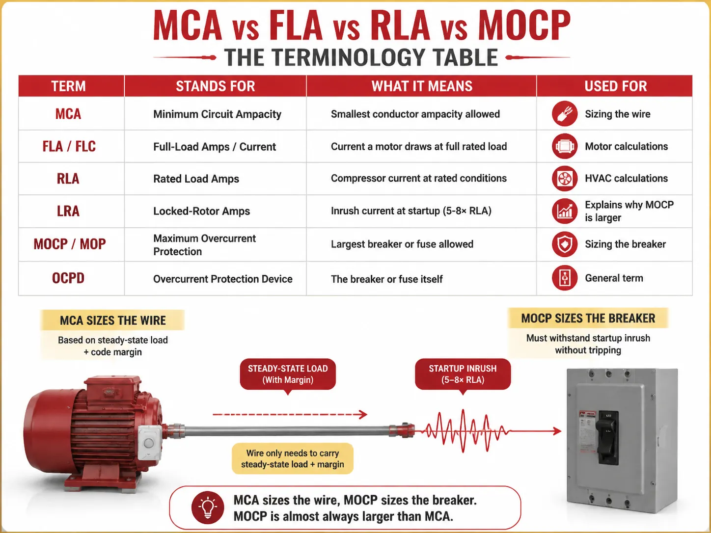
MCA vs FLA vs RLA vs MOCP: Terminoloji Tablosu
MCA ile ilgili karışıklığın yarısı, isim plakasındaki yanındaki harf kombinasyonlarından kaynaklanmaktadır. İşte her terimin gerçek anlamı:
| Terim | Anlamı | Ne Anlama Gelir | Kullanım Amacı |
|---|---|---|---|
| MCA | Minimum Devre Amperajı | İzin verilen en küçük iletken amperajı | Kablo boyutlandırma |
| FLA / FLC | Tam Yük Amperi / Akımı | Bir motorun tam yükte çektiği akım | Motor hesaplamaları |
| RLA | Derecelendirilmiş Yük Amperi | Derecelendirilmiş koşullarda kompresör akımı | HVAC hesaplamaları |
| LRA | Kilitli Rotor Amperi | Başlangıçta giriş akımı (5-8× RLA) | MOCP'nin neden daha büyük olduğunu açıklar |
| MOCP / MOP | Maksimum Aşırı Akım Koruması | İzin verilen en büyük kesici veya sigorta | Kesicinin boyutlandırılması |
| OCPD | Aşırı Akım Koruma Cihazı | Kesici veya sigortanın kendisi | Genel terim |
Zihinsel modellemenin ana bileşeni, bu hesaplamada yer alan iki farklı parametrenin dikkate alınmasıdır — MCA ve MOCP, bunlar aynı rakamlar değildir — ilki genellikle ikincisinden daha küçüktür çünkü kesici, ekipman başlatıldığında akımdaki ani artışı karşılamak zorundadır, kablo ise devam eden akım akışını ve kodlar tarafından belirlenen faktörleri karşılar.
125% Kuralı Açıklaması
125% kuralı, MCA için yapılan her hesaplamanın temelini oluşturur. NEC’in çeşitli bölümlerinde bulunabilir ve her birinde amaç, ya sürekli çalışan yükler ya da giriş akımı ile açılan yükler için belirli bir güvenlik payı sağlamaktır.
- NEC 210.19(A)(1) — dal devreleri: kablolar, sürekli yükün en az 125% amperajına ve sürekli olmayan yükün 100% amperajına sahip olmalıdır. Bir yük, ilgili yükün 3 saat veya daha uzun süre tam değerinde çalışması durumunda “sürekli yük” olarak adlandırılır (NEC 100 tanımı).
- NEC 215.2 — besleyiciler: aynı 125% gereksinimi besleyiciler için de geçerlidir.
- NEC 430.22 — bir motor: kablolar, motorun FLA’sının 125%’sine göre hesaplanmalıdır.
- NEC 440.22 / üretici uygulaması — HVAC: MCA = en büyük motorun RLA’sının 125%’si.
Neden 125%? Bunun iki nedeni vardır. İlk olarak, sürekli ısı yoktur: bir kablo, nominal akımını uzun süre taşıdığında, maksimum sıcaklığına kadar ısınır. Ekstra 25%, izolasyonun serin kalmasını sağlar. İkinci olarak, herhangi bir motorun normal modda çalışırken başlatılması, motorun gerçek çalışması sırasında olduğundan çok daha fazla akım çeker.
MCA Nasıl Hesaplanır (Çalışılmış Örneklerle)
Bireysel motorlar için (NEC 430.22 koduna göre),
MCA = motor FLA × 1.25
Örneğin, FLA’sı 17 A olan 3 HP, 230V tek fazlı bir motor varsa, o zaman,
MCA = 17 × 1.25 = 21.25 A. Şimdi, NEC tablo 310.16'ya (75 °C sütunu) göre, bu 21.25 A değerini taşıyabilen küçük telin 12 AWG olduğu ve bunun 25 A akım taşıma kapasitesine sahip olduğu çıkarılabilir.
Çoklu yük sistemi için (NEC 430.24),
MCA = (en yüksek motor FLA × 1.25) + diğer tüm motor SLA'ları
| Yük | FLA (Amper) | Çarpan | Katkı |
|---|---|---|---|
| En büyük motor (10 HP, 460V) | 14.0 | ×1.25 | 5 A |
| İkinci motor (5 HP) | 7.6 | ×1.00 | 6 A |
| Üçüncü motor (2 HP) | 3.4 | ×1.00 | 4 A |
| Toplam MCA | 5 A | ||
5A için, NEC 310.16 (75°C) 10 AWG bakır (35A) telin en küçük uygun boyut olduğunu belirtir — 12 AWG (25A) çok küçük olur.
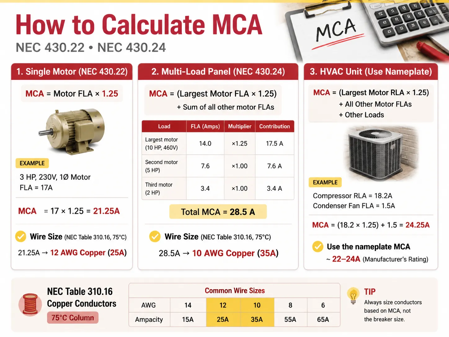
Kompresör ve fan motoru olan bir HVAC ünitesi durumunda, ideal RLA değerleri şu şekilde olur: MCA = (En Büyük Motor RLA × 1.25) + Diğer Motorların FLA'ları + Diğer Yükler.
Örneğin, kompresörün RLA'sı 18.2 Amper ve kondanser fanın FLA'sı 1.5 Amper ise, şu hesaplama yapılır: MCA = (18.2 × 1.25) + 1.5 = 24.25 Amper.
Lütfen bu değerin üretici tarafından HVAC ünitesinin isim plakasında daha standart olan 22-24 Amper aralığına yuvarlandığını unutmayın.
MCA ve Maksimum Aşırı Akım Koruması (MOCP)
Burada amatörler genellikle hata yapar: kesicinin MCA ile eşleşmesi gerektiğini düşünürler. Gerekmiyor. Kesici, isim plakasındaki sayıdan farklı olan MOCP'ye göre derecelendirilir.
| Faktör | MCA (Tel) | MOCP (Kesici) |
|---|---|---|
| Neyi boyutlandırır | İletken (tel) | Aşırı akım cihazı (kesici/füze) |
| Tipik ilişki | Daha küçük sayı | Daha büyük sayı (akım yükselişine izin vermeli) |
| Koruduğu şey | İzolasyonun aşırı ısınması | Kısa devre ve toprak hatası |
| Kural | Tel ampasitesi ≥ MCA | Kesici boyutu ≤ MOCP (NEC 240.6 standart boyutlarına göre) |
| Örnek ünite | MCA 26.4A | MOCP 45A |
Bu durumda, 10 AWG (30-35A ampasite) bakır tel üniteye güç sağlamak için kullanılır ve 45A kesici ile dalgalanmalara karşı korunur. Telden daha yüksek derecelendirmeye sahip bir kesici kullanmak izinli midir? NEC 440.22(a) uyarınca izinlidir çünkü kompresörün kendi koruma mekanizmaları vardır. Bu nedenle, bu durumda kesiciden sadece dalgalanmalara karşı koruma gereklidir. Bu, motor ve HVAC sistemleri için geçerlidir; normal kablolama sistemleri hariçtir, burada kesicinin telden daha düşük derecelendirmeye sahip olması gerekir.
Doğru AWG Tel Boyutunu Seçme
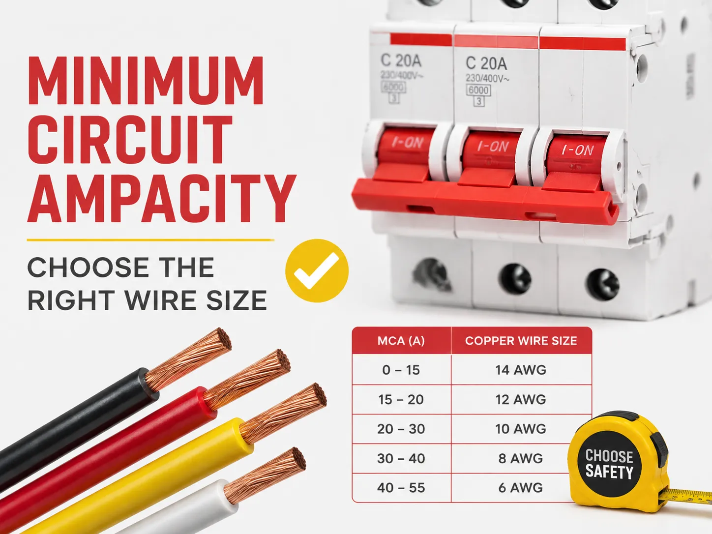
MCA olduğunda, tel seçimi basitçe NEC Tablo 310.16'ya başvurmak demektir. THHN/THWN-2 bakır (kanallar için standart tel) kullanırken 75°C sütununa, NM-B (Romex) veya eski tesisat kablolaması kullanılıyorsa 60°C sütununa bakınız.
| Bakır Tel Boyutu (AWG) | 60°C'de Ampasite | 75°C'de Amperaj Kapasitesi | Kapsadığı MCA'ya Kadar | Tipik Kesici |
|---|---|---|---|---|
| 14 AWG | 15 A | 20 A | 15-20 A | 15 A |
| 12 AWG | 20 A | 25 A | 20-25 A | 20 A |
| 10 AWG | 30 A | 35 A | 30-35 A | 30 A |
| 8 AWG | 40 A | 50 A | 40-50 A | 40 A |
| 6 AWG | 55 A | 65 A | 55-65 A | 60 A |
| 4 AWG | 70 A | 85 A | 70-85 A | 80 A |
| 2 AWG | 95 A | 115 A | 95-115 A | 100 A |
| 1/0 AWG | 125 A | 150 A | 125-150 A | 150 A |
| 2/0 AWG | 145 A | 175 A | 145-175 A | 175 A |
| 3/0 AWG | 165 A | 200 A | 165-200 A | 200 A |
Ampasitesi, derecelendirilmiş amperajına (aşağıda açıklanan derating sonrası) en az eşit olan en küçük kabloyu seçin. 24,25A derecelendirilmiş amperaj için kullanılabilecek en küçük kablo 12 AWG (25A) dir. Ancak, birçok montajcı uzun mesafeler ve/veya gelecekteki ihtiyaçlar için 10 AWG gibi daha büyük bir kablo kullanır.
200 Amper Servis: 1/0 Kablo Kullanabilir misiniz?
Bu soru genellikle konut servis yükseltmeleri ile ilgili olarak sorulur ve cevap, 200A tam servis için, bu eski ama yanlış bir hayırdır. 75°C göz önünde bulundurulduğunda, 1/0 bakır kablo maksimum 150A derecelendirmeye sahiptir ve yasa gereği 200A servis yükünü taşıyamaz. 200A konut servisi sağlamak gerekiyorsa, aşağıdaki bakır veya alüminyum kablo türlerinden biri kullanılmalıdır:
- 75°C sıcaklıkta 175A taşıyabilen 2/0 bakır. Bu kablo bazı bölgelerde 200A için izinlidir (Özel Ticari Kod A ile).
- 75°C'de 200A yükü başarıyla taşıyabilen 3/0 bakır.
- 75°C'de 180A besleyebilen 4/0 alüminyum kablo, genellikle 200A kablolama gerektiren servis giriş hatlarında kullanılır.
Diğer bir seçenek, yalnızca 150A servis hatları ve 150A alt panel için uygun olan 1/0 bakır kablo kullanmaktır. 1/0 kabloyu 200A servis hattında kullanmaktan kesinlikle kaçının çünkü uzun süre işlendiğinde aşırı ısınır. Ayrıca, NEC 310.12 Servis Girişi ile ilgili birçok belirsizlik olduğundan yerel kablolama kodu ve denetleyici ile doğrulama yapın.
Devre Kesiciler için 80% Kuralı
NEC 210.20(A) ve 215.3 kuralları, bir devre kesicinin derecelendirmesinin 80%'sinden fazla yüklenmemesi gerektiğini belirtir. Örneğin:
- 15A kesici sadece 12A sürekli yük taşımalıdır.
- 20A kesici sadece 16A sürekli yük taşımalıdır.
- 30A kesici sadece 24A sürekli yük taşımalıdır.
- 100A kesici sadece 80A tam yük taşımalıdır.
Yukarıdaki tüm örnekler arasında karşılaştırmalar yapın. Yönetmeliğin arkasındaki prensip her iki durumda da aynıdır: 80% ve 125% faktörleri özünde aynıdır ve maksimum yükün cihazın derecelendirilmiş kapasitesinden yüksek olmaması gerektiğini belirtir ve belirli bir oranla ifade edilir (1/1.25=0.8). Örneğin, cihaz 16A sürekli yükle kullanılıyorsa, iletken 16*1.25=20A dayanmalıdır; dolayısıyla, ilgili kesici 20A yük için derecelendirilmelidir ve aslında sadece 20A olarak derecelendirilmiştir. Yeni bir devre için koruma cihazlarını eşleştirmeniz gerektiğinde, iş için derecelendirilmiş sertifikalı mini devre kesici serisi — örneğin HUYU HUM18 MCB serisi 1P'den 4P'ye ve B/C/D eğrilerini kapsayan — pano üreticileri ve müteahhitler için kablo-kesici eşleşmesini kolaylaştırır.
Sıcaklık ve Kanal Doluluk Derating'i
Ampasite tablosu, 30 derece Santigrat (86 derece Fahrenheit) ortam sıcaklığı varsayımına dayanır ve bir boru içinden 3'ten fazla tel geçmez. Sıcaklık değiştiğinde, MCA ile karşılaştırmadan önce telin ampasitesini düşürmeniz gerekir.
- Yüksek ortam sıcaklığı: NEC Tablo 310.15(B)(1)'e göre düzeltme faktörleri kullanılabilir. Örneğin, 75°C için derecelendirilmiş bir iletkenin taşıma kapasitesi, ortam sıcaklığı 40°C olduğunda 0,88 ile çarpılarak 22A olur.
- Boru dolumu: Çoğu durumda, NEC Tablo 310.15(C)(1), boru içinden geçen tel sayısına göre farklı düzeltme faktörleri belirtir. Böylece, 4-6 iletken için düzeltme faktörü 0,80; 7-9 iletken için 0,70; ve 10-20 için 0,50'dir. Daha fazla tel sayısı, boru içinde daha fazla ısının hapsolmasına yol açar.
- Norm: derecelendirme koşulundan sonra, yeni ampasite MCA'dan az olmamalıdır.
Uzun Hatlarda Gerilim Düşümü
ABD'nin çoğu yerinde, gerilim düşümü bir kod gerekliliği değildir (bazı uygulamalar hariç) ancak yine de faydalı ve akıllıdır: dal devre gerilim düşümü %3'ü geçmemeli ve tüm besleyici + dal devre gerilim düşümü %5'i geçmemelidir. İyi bir kılavuz, mesafe 50 ila 100 feet'i aştığında bir numara daha büyük tel kullanmaktır. Yani 120 voltluk bir devre 150 feetten uzun ise, MCA tablosu 12 AWG kullanılabileceğini söylese bile daha büyük tel boyutu kullanmalısınız (10 AWG daha iyi performans sağlar). Yanlış tel boyutu uzun mesafelerde kullanılırsa, ışıklar sönükleşir, motorlar yavaşlar ve aşırı ısınma olur.
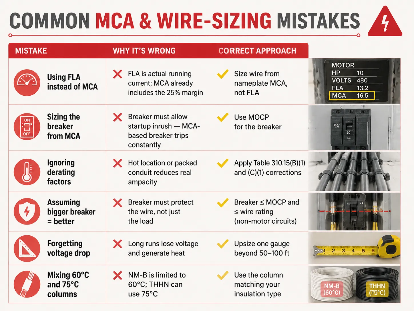
Yaygın MCA ve Tel Boyutlandırma Hataları
| Hata | Neden Yanlış | Doğru Yaklaşım |
|---|---|---|
| MCA yerine FLA kullanmak | FLA gerçek çalışma akımıdır; MCA zaten marj içerir | Tel boyutunu isim plakası MCA'sından belirleyin, FLA'dan değil |
| Kesici boyutlandırmasını MCA'dan yapın | Kesici, başlangıç akımına izin vermelidir — MCA bazlı kesici sürekli atar | Kesici için MOCP kullanın |
| Derecelendirme faktörlerini göz ardı etmek | Sıcak ortam veya dolu boru gerçek ampasiteyi düşürür | Tablo 310.15(B)(1) ve (C)(1) düzeltmelerini uygulayın |
| Assuming bigger breaker = better | Breaker must protect the wire, not just the load | Breaker ≤ MOCP and ≤ wire rating (non-motor circuits) |
| Forgetting voltage drop | Long runs lose voltage and generate heat | Upsize one gauge beyond 50-100 ft |
| Mixing 60°C and 75°C columns | NM-B is limited to 60°C; THHN can use 75°C | Use the column matching your insulation type |
Typical MCA Values for Common Equipment
| Equipment | Typical MCA | Wire Size (75°C copper) | MOCP / Breaker |
|---|---|---|---|
| 3 HP 230V motor | ~21.3 A | 12 AWG | 30 A |
| 5 HP 230V motor | ~26.3 A | 10 AWG | 40 A |
| 10 HP 460V motor | ~17.5 A | 12 AWG | 25-30 A |
| 3.5-ton heat pump | ~22-26 A | 10 AWG | 30-45 A |
| 5-ton AC unit | ~30-35 A | 8 AWG | 45-60 A |
| Level 2 EV charger (48A) | ~60 A | 6 AWG | 60 A |
| Electric water heater (4500W/240V) | ~23.4 A | 10 AWG | 30 A |
| 200A residential service | Uygulanamaz | 2/0-3/0 copper or 4/0 aluminum | 200 A main |
These are general figures — you should regularly refer to the nameplate of your unit. Also, when you are designing or enlarging your distribution installation, ensuring that the protection devices suit the cables is the kind of issue which certified equipment produced by a manufacturer ensuring the whole range addresses: understanding what a 15-amp circuit can actually carry is a good starting point, and for replacement decisions our guide on bir devre kesicinin bozuk olup olmadığını nasıl anlayacağınız covers the inspection side of the story.
Sıkça Sorulan Sorular
What is the 125 rule for breakers?
According to the 125% rule (NEC 210.19, 215.2, 430.22), conductors must be sized at 125% of the continuous load, or 125% of the motor’s full-load amps. In the case of the breaker, it can be seen that the same philosophy is entailed in the 80% rule, meaning that the breaker can only sustain 80% of its rating over time. Both are used to prevent overheating of the insulation. One example would be the case when the continuous load of 20A requires conductors of 25A rating (12 AWG) and a breaker rated 25A or 30A, while only 20A is used continuously in the circuit.
Can I use 1/0 wire for 200 amp service?
1/0 copper can carry 150A current at 75° C. Thus, 1/0 copper is not an appropriate option for 200A power. The right options include either 2/0 copper, good for 175A, or 3/0 copper of 200A. 4/0 aluminum can also be considered as it is good for 180A. In the case of a power of less than 150A, 1/0 copper can be successfully used. Consult a local inspector as NEC 310.12 states that service entrance has its own exceptions.
Will a 100 amp breaker accept 1/0 wire?
In most cases, if the terminal of the breaker is okay for it, then yes—most of the terminals for 100A breakers can take a wire sized up to 2/0 copper or 4/0 aluminum. However, a 100A breaker does not need a wire gauge of 1/0; the only determining thing is the load as it is what tells us what wire size to use in this instance; as an example, when the load is only 70A, then 4 AWG (85A) is the right size. It is important to read the information given on the terminals of the breaker because it is what offers all the necessary information.
What is the 80% rule for circuit breakers?
The 80% rule (NEC 210.20(A), 215.3) indicates that a breaker is limited to carrying 80% of its rating for continuous loads. For example, a 15A breaker has a continuous current maximum of 12A, whereas a 20A breaker can carry 16A and a 100A breaker can carry 80A. There is a balance in the safety margin because it mirrors the 125% rule of current rating in conductors. The full breaker rating can be used for non-continuous loads since they do not follow this rule.
Referanslar
- NFPA 70 — National Electrical Code (NEC), Articles 210, 215, 240, 310, 430, 440
- OSHA 1910.303 — Electrical Systems: General Requirements
- Mike Holt — NEC Code Change Explanations (125% / 80% rules)
- EC&M Magazine — Conductor Sizing and MCA/MOCP Applications
- ENERGY STAR — HVAC Installation and Circuit Sizing Guidance
- NEMA — Motor and Electrical Product Standards
Sonuç
Minimum circuit ampacity provides the lowest size of wire that can be used for different types of equipment. The number is calculated based on the 125% rule by taking the largest current load or motor load multiplied by 1.25 and adding other loads to get the calculation. The wire size is determined by the MCA but the size of the breaker is determined by a separate number called MOCP. Be aware of applicable features such as the 80% rule for continuous loads, derating for heat as well as conduit fill, and voltage drop on long runs to avoid the problems of underused wires as well as wasted copper. And when a replacement breaker or panel upgrade is part of the job, understanding breaker replacement costs and the differences between protection devices like MCBs and MCCBs helps you plan the whole circuit — not just the wire.