
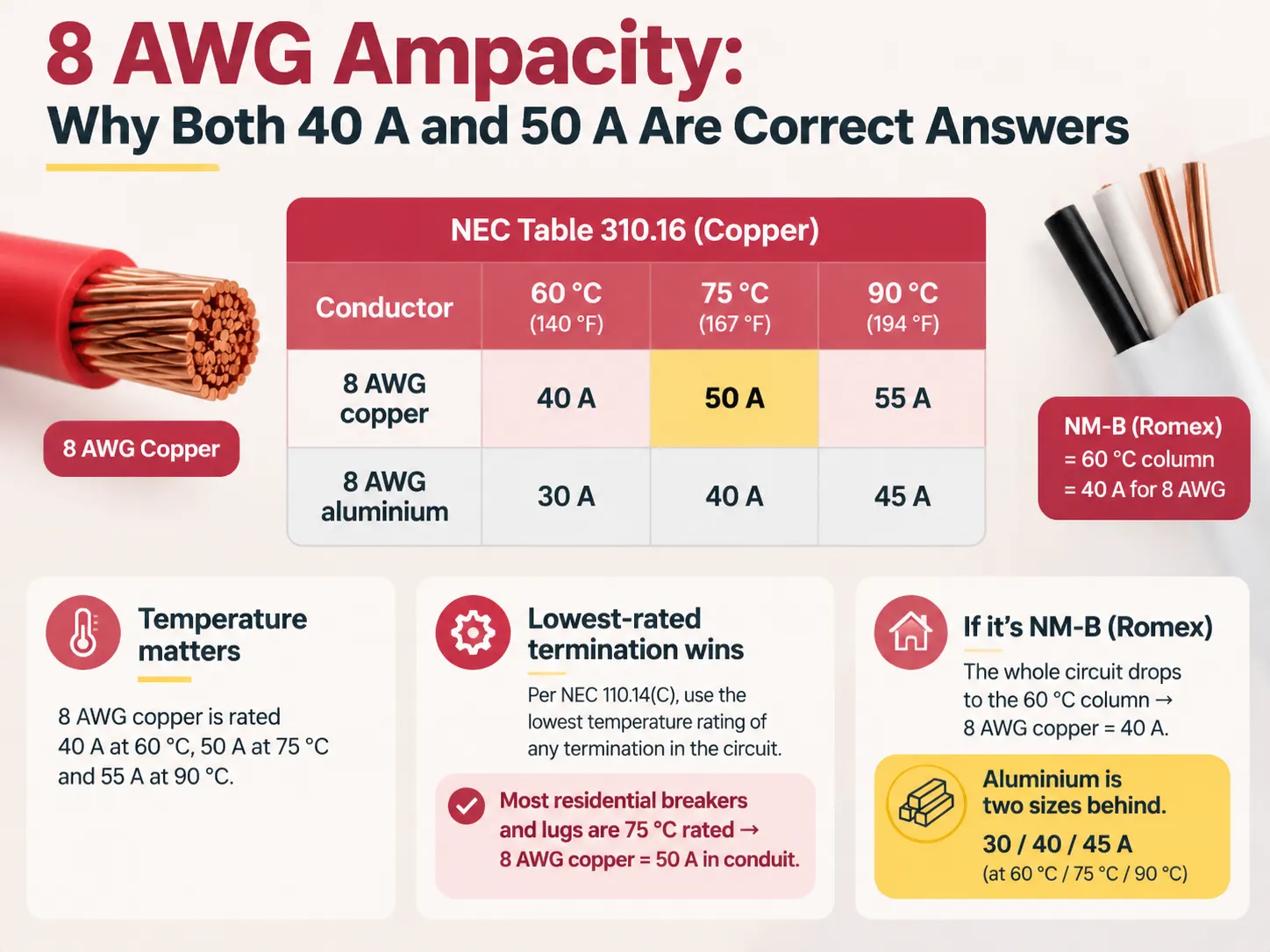
If you look for 8 AWG wire ampacity on the internet you will often find such answers as 40, 50 or 55 amps. These statements match as people refer to the same table and understand it correctly. The difference lies in other aspects which are not connected with copper such as the rating of insulation, the temperature rating of terminals and the presence of free air.
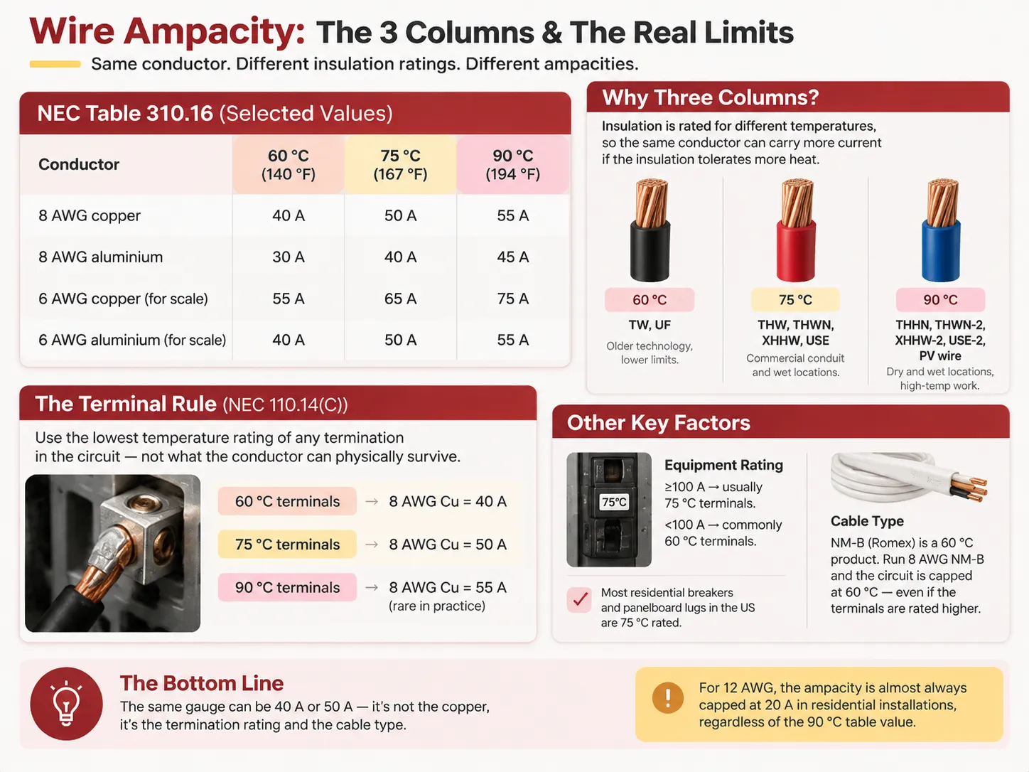
Briefly, the rating for 8-gauge copper is about 40 A at 60 degrees Celsius, 50 A at 75 degrees Celsius, and 55 A at 90 degrees Celsius, as shown in the NEC table 310.16. The rating to be used will be the lowest rated in the circuit as stated by NEC code 110.14(c): since in most residential houses, the lugs and breakers are rated 75 degrees, thus making 8-gauge copper a 50 A conductor in conduit. Any wiring on the run done in NM-B (Romex) conduit will make the rating go down to column 60 degrees, thus making it a 40 A conductor.
What 8 AWG Actually Is
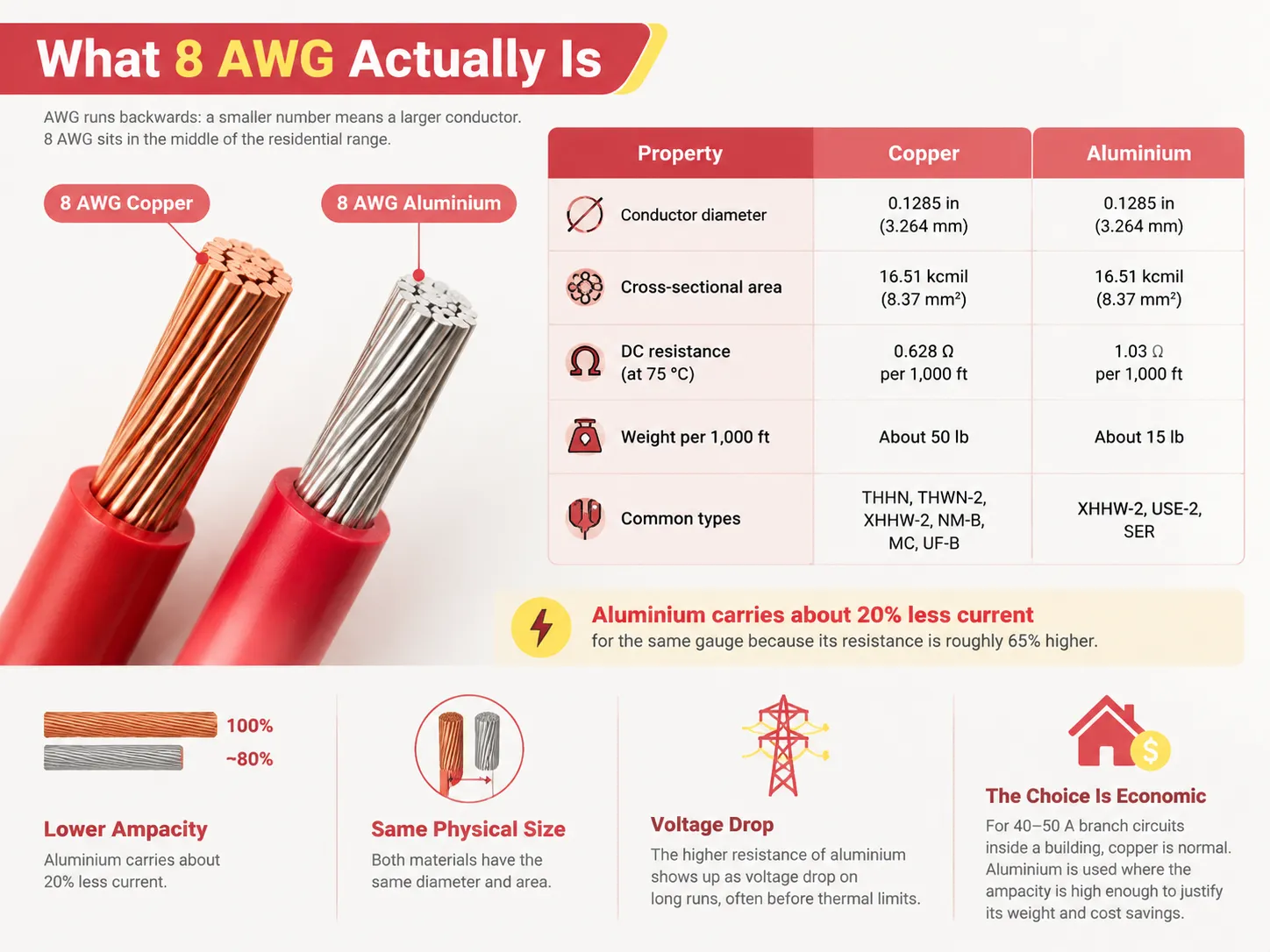
American Wire Gauge is backward; the smaller the number, the bigger the wire. 8 AWG is in the middle of the home range, above 14, 12, and 10 AWG used for regular branch circuits, but below 6 and 4 AWG that are used for larger feeders and service entrances.
| Propiedad | Cobre | Aluminium |
|---|---|---|
| Conductor diameter | 0.1285 in (3.264 mm) | 0.1285 in (3.264 mm) |
| Cross-sectional area | 16.51 kcmil (8.37 mm²) | 16.51 kcmil (8.37 mm²) |
| DC resistance at 75 °C | 0.628 Ω per 1,000 ft | 1.03 Ω per 1,000 ft |
| Weight per 1,000 ft | About 50 lb | About 15 lb |
| Common types | THHN, THWN-2, XHHW-2, NM-B, MC, UF-B | XHHW-2, USE-2, SER |
Although both metals come in the same size, they behave very differently. Aluminum has about 20% less ampacity than the same gauge of wire in copper. This is because its resistance is approximately 65% greater than copper’s resistance. The result is that aluminium’s industry guideline suggests that it tends to run two sizes under copper. For long runs of wire, the difference in resistance shows itself as a voltage drop before approaching thermal limitation
The choice between the two is usually economic rather than technical, and it has a long history on both the utility side and the branch-circuit side of an installation — the reasoning behind it is set out in this explanation of why copper and aluminium are both used for power transmission. For a 40 or 50 amp branch circuit inside a building, copper is the normal answer; aluminium appears mainly where the ampacity is large enough that the weight and cost savings outweigh the upsizing.
The Ampacity Table, and Why There Are Three Columns
The numbers have been sourced from NEC Table 310.16, which indicates the permitted ampacities of insulated conductors of not more than 2000 Vs and operating at a temperature of 30 C with no more than three current carrying conductors in a conduit or cable.
| Conductor | 60 °C (140 °F) | 75 °C (167 °F) | 90 °C (194 °F) |
|---|---|---|---|
| 8 AWG copper | 40 A | 50 A | 55 A |
| 8 AWG aluminium | 30 A | 40 A | 45 A |
| 6 AWG copper (for scale) | 55 A | 65 A | 75 A |
| 6 AWG aluminium (for scale) | 40 A | 50 A | 55 A |
Columns are necessary because insulation has been produced with different temperature ratings, and conductor may carry more current prior to overheating as a result of insulation capable of tolerating expected temperature.
- 60 °C insulation: TW, UF. Older technology, lower limits.
- 75 °C insulation: THW, THWN, XHHW, USE. Regular conduit, wet locations of commercial applications.
- 90 °C insulation: THHN, THWN-2, XHHW-2, USE-2, PV wire. Dry and wet locations along with high-temperature working conditions.
One thing to highlight regarding 90 °C is that it often causes confusion when dealing with wires of that size because the 90 °C column is a derating basis and not a rating that should be used for termination. It is used to determine how ambient temperature and bundling of conductors affect calculations, and only then it can be checked against the temperature column that can be used for specific terminations. 55 A cannot be used as a derivative figure for 8 AWG copper as it violates the code.How the ampacity determination works step by step, including the correction and adjustment factors, is covered in this walkthrough of how minimum circuit ampacity is established.
The Terminal Rule That Decides the Answer
According to NEC 110.14(C), I must select conductor ampacity based on the lowest temperature rating of any termination, not on the maximum withstandable temperature of the conductor insulation. In other words, the limiting factor is the connections and not the conductor itself.
In practice:
- Terminals rated 60 °C → the 60 °C column should be used → copper 8 AWG = 40 A.
- Terminals rated 75 °C → the 75 °C column should be used → copper 8 AWG = 50 A.
- Terminals rated 90 °C → the 90 °C column should be used → copper 8 AWG = 55 A – which, in practice, almost never applies.
Equipment rated 100 A or more will normally get a listing for terminations rated 75 °C, whereas equipment rated under 100 A will typically be listed for terminations rated 60 °C; hence where 40 A comes from. Most residential circuit breakers and panelboard lugs sold in the US are 75 °C rated, allowing for a large number of specific real-life applications with 8 AWG cables at 50 A – provided that the actual ratings have been checked against the claims of the breaker label, panelboard listing, and appliance nameplate.
The second 40 A comes from the cable type. NM-B, commonly known as Romex, is a 60 °C cable, meaning that 8 AWG conductors in NM-B will typecast the whole circuit as using the lower column even if other connections are rated higher. As a result, the same gauge may be used as a 40 A conductor in one application and a 50 A in another just twenty feet away.
The same logic explains why 12 AWG is capped at 20 A in almost every residential situation even though a 90 °C insulated 12 AWG conductor can carry 30 A in the table. Below 8 AWG the numbers are locked down by the small-conductor rule; at 8 AWG they are not, which makes this size genuinely dependent on the installation details.
Breaker Sizing: 240.4 and the Next-Size-Up Rule
Most online guides falsely state the following: NEC 240.4(D) does not apply to 8 AWG. The small conductor rule pertains to 18, 16, 14, 12, and 10 AWG, and states that the maximum rating is 15 A for the 14 AWG copper, 20 A for the 12 AWG copper, and 30 A for the 10 AWG copper. Because 8 AWG surpasses the limit, the rule in NEC 240.4 applies directly to it, and it is protected by the general rule, where NEC 240.4(B) grants a right to use the next standard overcurrent device size after the ampacity of the wire.
The calculations for 8 AWG copper with the temperature of 75 °C are as follows:
- Ampacity: 50 A.
- Sizes of circuit breakers: 15, 20, 25, 30, 35, 40, 45, 50, 60, 70, 80.
- Next standard size is 45 A, then 50 A. Because the ampacity of the wire is 50 A, one can use a 50 A circuit breaker at 75 °C.
However, there are two constraints. First, because NEC 240.4(D) does not set a limit on the size of 8 AWG wire, it becomes your sole obligation to confirm this or that rating for the amperage of the circuit breaker, so you have to be confident in your calculation. Besides, NEC 240.4(B) is not suitable for multioutlet power circuits, so 50 A circuit breaker at 8 AWG is forbidden under this condition.
If you need to have the circuit of 60 A, there is no way to use 8 AWG copper for that. Where the breaker sits in a two-pole configuration and how that affects the rest of the circuit is a separate question, and the differences are laid out in this comparison of 50 amp single-pole and double-pole breakers.
Derating: When 8 AWG Stops Being Enough
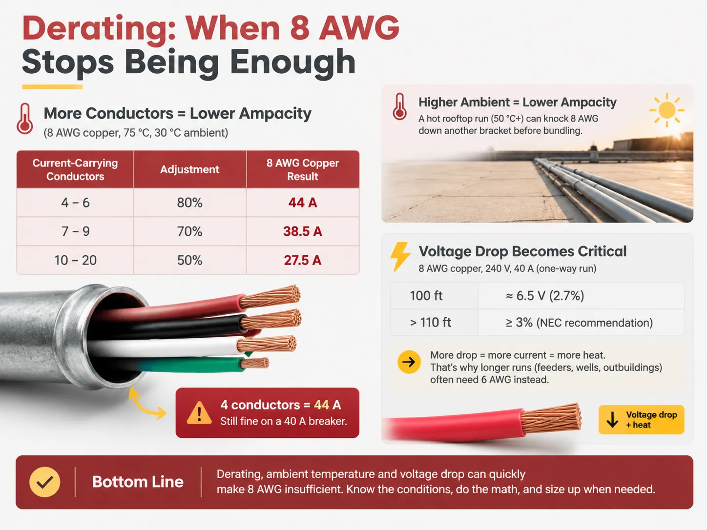
The table prescribes only a maximum of three current-carrying conductors and 30 °C of ambient temperature, but both assumptions are usually inaccurate. At 8 AWG, this creates an immediate problem, as no small conductor backstop will save you.
| Condición | Adjustment | 8 AWG copper result |
|---|---|---|
| 4–6 current-carrying conductors | 80% | 55 A × 0.80 = 44 A |
| 7–9 current-carrying conductors | 70% | 55 A × 0.70 = 38.5 A |
| 10–20 current-carrying conductors | 50% | 55 A × 0.50 = 27.5 A |
For example, when looking at the first row of the table, if we run four wires of 8 AWG THHN copper through one PVC conduit, we get derated ampacity of 44 A. If we then compare this with the terminal value of ampacity at 75°C which is 50 A, we get 44 A, which means we are fine with our 40 A breaker. If we keep adding conductors to bring the count to seven, the derated ampacity drops to 38.5 A. At this stage, we cannot use 8 AWG wire any longer and we need to switch to 6 AWG wire.
Ambient temperature adds to the problem. The ampacities of wires are determined under the assumption of ambient temperature of 30 C. Under the hotter conditions, correction factors come into play. If we have a conduit running on the roof in hot climate, it gets real hot, around 50 C, and even before we account for the factors of bundling this brings our 8 AWG ampacity down another notch. Finally, if we have continuous load amounting to 125% of the wire’s capacity, we are likely to end up with disappointed numbers on the end of our calculations.
Voltage Drop: The Constraint That Stops Being Theoretical
It is at 8 AWG that one should start to refer to voltage drop as a determining factor when selecting the wire size rather than confirm it. For example, stranded 8 AWG copper has a DC resistance of roughly 0.628 Ω/1000 ft when the temperature is 75 °C. AC resistance is even higher.
Now, a 240 V circuit carrying 40 A would provide the following values: with 100 ft run in one direction, the voltage drop would be approximately 6.5 V or around 2.7%. So, anywhere from 110 ft onward you will face the NEC’s allowed maximum since the 3% limit for branch circuits is highly recommended.
3% and 5% limits are recommendations that are not legally enforced, but recommendations are there for a reason. If the voltage reaches 5%, due to this under-voltage a motor would draw more current than with the normal voltage leading to potential heating of wires. It is usually the case that the most often used 8 AWG circuit would require more powerful wires to cope with the distance. Sizing a feeder for a large service makes the trade-off concrete in the same way, as this guide to wire sizing for a 100 amp service shows.
What 8 AWG Is Actually Used For
The uses of the material are derived from the ratings. 8 AWG copper wire allows for carrying currents within the range of 40–50 A according to known applications, including:
- Feeders for subpanels. The 8/3 cable connecting the subpanel drawing a current of 40 or 50 A in the garage, for instance, provided the sum of the load and the connection distance do not exceed the limits;
- AC and heat pump units. Many central air conditioning units require maximum protection against overcurrent being equal to 40/50 A;
- Electric powered water heaters. Tank water heaters having a power of 9 kW and working at 240 volts may be equipped with heaters using 8/2 wire and a breaker rated at 40 A.
- Cooktops and wall ovens. Relatively small separated units may be powered by 8 AWG cables, however, many ovens require the use of 6 AWG wire nowadays.
- Generators and transfer switches. The 8/3 SOOW portable generator cable supplies a 50 A inlet box;
- Electric charging for EV vehicles. A regular 8 AWG job is represented by a charger rated for 32 A and using a 40 A breaker.
- Solar PV circuits. This circuit must meet the requirements of the NEC Article 690, where 8 AWG THHN or PV types of wire for wire runs suitable for source and output are widely used.
Note that most of these circuits are circuits dedicated to a single unit of load rather than multi-outlet circuits, which is not accidental. The reason for the difference in application is that a dedicated circuit has only one known load, thus allowing for the definite answer for derating and terminal issues. Multi-outlet circuits, on the contrary, do not lead to such definite answer because the reason for the difference is that the two types of circuits are treated differently by electrical code.
Grounding Conductor and Cable Configurations
The equipment grounding conductor is determined by the rating of the overcurrent device rather than the ungrounded conductors. For a circuit rated at 40 or 50 A, table 250.122 advises a 10 AWG copper wire. The wire does not have to correspond to the wire size of the hot wires, and therefore, it is unnecessary to oversize the grounding conductor simply because the hot conductors are bigger.
| Configuración | Conductors | Uso típico |
|---|---|---|
| 8/2 | Hot, neutral, ground | Water heater, 240 V load with no neutral requirement |
| 8/3 | Two hots, neutral, ground | Subpanel feed, 120/240 V mixed loads, generator inlet |
| 8/4 | Three hots, neutral, ground or four conductors for three-phase work | Three-phase equipment and specialized feeders |
The figure that follows the slash indicates the quantity of conductors carrying the current, rather than the grounding conductor. As a result, the number of wires used in an 8/2 cable is three. Knowing whether the load will require a neutral conductor is vital when determining the cable configuration for that subpanel, for this will determine whether it will work for 120-volt circuits or not at all.
A Five-Step Method for Any 8 AWG Job
- Determine the lowest rating of terminals in the circuit. The options are the label of the breaker, the listing of the panelboard, and the nameplate of the appliance. This becomes the column to use.
- Then you have to identify the kind of the cable or conductor. If any of these types is NM-B, it means the current drops to the 60 degrees Celsius column despite the terminals’ ratings.
- Then proceed with the 90-degree Celsius value for derating. It equals 55 amperes for copper and 45 amperes for aluminum. Also, don’t forget to apply the correction factors, including conductor-count and ambient temperature correction factors.
- Choose the minimal value among the derated value and the terminals value, and that is the real ampacity.
- Now determine the size of the breaker based on that value by selecting the smallest size mentioned in 240.4(B), remembering that 240.4(D) doesn’t apply to 8 AWG and 240.4(B) does not apply to the multi-outlet receptacle circuits.
Make sure you check the voltage drop over the actual length of the run and upsize if the wire needs to be improved. If something changes in the point number five, then the wire should be recalculated, while the calculations will stay the same.
Preguntas Frecuentes
How many amps can an 8 AWG handle?
An 8 AWG copper wire is capable of carrying an electrical current of 40 A for a temperature of 60°C, 50 A for a temperature of 75°C, and 55 A for a temperature of 90°C according to NEC Table 310.16. An 8 AWG aluminum wire will carry 30 A for a temperature of 60°C, 40 A for 75°C, and 45 A for 90°C, but it will not carry the highest possible current for the three given temperatures. The limiting factor in those instances is the lowest current considering the termination method, material of cable, and derating values; in practical applications, this value is usually around 40 A when NM-B aluminum cable is used and approximately 50 A when utilizing conduit installation operating at 75°C.
Is 8 AWG good for 40 amps?
Indeed, this is a prudent decision. Copper’s rating at a temperature of 60 degrees Celsius is an important factor in the use of NM-B cable regarding compliance, which in the case of an 8 AWG copper NM-B circuit powered by a 40 amp breaker is guaranteed. Mostly, this is how various domestic HVAC equipment are rated.
Will 8 AWG carry 60 amps?
When handling standard installations, an 8 AWG copper wire will not carry more than 55 A even at the temperature of 90 °C, and so that number applies to the derating of the wire, rather than its terminal capacity. To get a current of 60 A, a wire of 6 AWG will be needed, with a terminal capacity of 65 A at 75 °C. Therefore, the claim that 8 AWG is able to carry a current of 60 A is based on the wrong column Read or best ignores 110.14(C).
Will 8 AWG handle 50 amps?
This is true in cases where termination ratings are 75 °C and the conductor is not NM-B. Table 310.16 indicates that the rating is 50 A at 75 °C for 8 AWG copper, which corresponds to the standard overcurrent device rating. Since 8 AWG is larger than the limit specified in the small conductor rule found in 240.4(D), it is allowed to use the 50 A circuit breaker according to 240.4(B) as long as this is not a multi-outlet branch circuit supplying receptacles. Always check the breaker and panel markings before using them.
Referencias
- NFPA — NFPA 70 National Electrical Code, Tables 310.16, 250.122 and 310.15(C)(1), and Sections 110.14(C), 240.4 and 690.8
- Southwire — conductor ampacity, resistance and cable construction data for building wire
- EC&M Magazine — ampacity adjustment, correction factor and terminal temperature guidance
- International Association of Electrical Inspectors — code interpretation on conductor sizing and overcurrent protection
- NEMA — building wire and cable standards, and terminal temperature rating practice
- Grainger — current US pricing and specification data for 8 AWG building wire and cable assemblies
- Eaton — circuit breaker terminal ratings and panelboard termination specifications
- US Department of Energy — residential wiring and electrical load guidance
Conclusión
The 8 AWG wire caters for three ampacity ratings, as it is subject to three thermal insulation, meaning that the ampacity rating to use is determined by the weakest termination used in the circuit, and the wire type. When using copper, the ampacity ratings will be 40 A at 60 C, 50 A at 75 C and 55 A at 90 C while with aluminum wire, the ratings are 30 A at 60 C, 40 A at 75 C and 45 A at 90 C, which means that the amperage rating of 8 AWG wire used in NM-B cable is 40 A, while for the wiring done with conduits is 50 A at 75 degree terminations. One has first to check the terminal ratings before dealing with the ampacity of the wire run, so that one has to repeat the following three steps one after another.