
A conveyor belt becomes stuck. The motor draws 38 amperes from the circuit that is rated for only 32 amperes for a duration of 90 seconds while someone goes to fix it. Everything is intact. The circuit breaker and all of its contacts are intact too. Although the coil rises its temperature 40 degrees Celsius higher than the limit given on the motor plate, insulation suffers and burns out within 3 weeks. An electric engineer is to be blamed. A new motor is bought. Another malfunction occurs within 3 months.
The distance between the statements “power consumption was too great” and “the circuit protection worked” is exactly the distance that generators were developed to cover. Situations involving this distance are among the most common occurrences of improper installation and setting of motor protection elements.
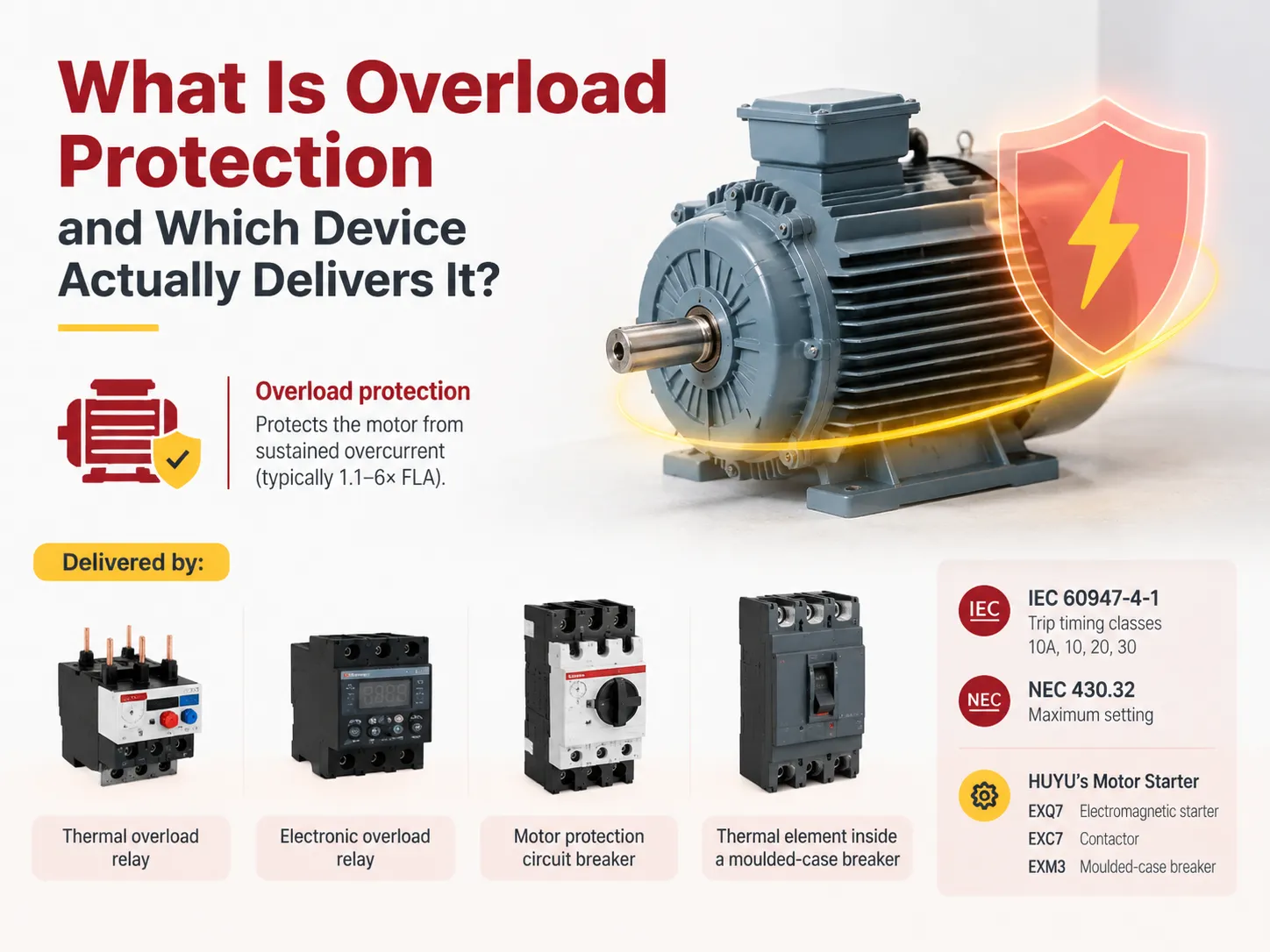
According to the quick answer, overload protection is a type of inverse timing that protects the motor from prolonged current above its rated operating limit but below the value of a short circuit. This kind of protection is provided by a thermal overload relay, an electronic overload relay, a motor protective circuit breaker, or the thermal element present inside a molded case breaker. The timings are dictated by IEC 60947-4-1 using classes 10A, 10, 20, and 30 and the upper limit of the setting is determined by NEC 430.32. HUYU manufactures ExQ7 electromagnetic starters, ExC7 contactors, and ExM3 molded case breakers to fulfill this function in the motor starts.
What Overload Protection Covers, and What It Does Not
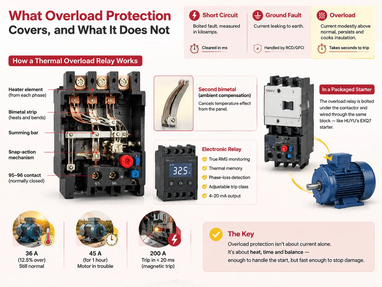
There are three types of faults that are often mixed up. Short circuit refers to an instantaneous fault that has a fault current that is measured in kiloamps and is just milliseconds long. Ground fault happens when fault current goes to ground and is taken care of by a RCD or GFCI. Overload is in between those two categories; this takes place when current is slightly over than normal for a prolonged time.
However, the differences are much smaller than people think. A 32 A motor that operates at 36 A is 12.5 % overloaded, which is ok on a hot summer day, but if that same motor runs at 45A, the winding will suffer from overheating. A case of running at 200 A would imply that the magnetic protection trip should work in less than 20 milliseconds.
Because of this, overload protection has to work noticeably slower. Being based on heat and not just the current, it means that if a device trips after two seconds reached 1.5 time full-load current, it will break down on each start-up of the device. It has to withstand the starting time while recognizing the overheating at the same time.
How the Trip Actually Happens
A thermal relay is designed in such a way that it contains two metallic components possessing differential expansion abilities. Such as, the bending action allows to reach out a preset threshold for triggering the snap action mechanism in case the bending exceeds a certain level.
In addition to that, a second bimetal powered by ambient temperature heats the other one which is in charge of the motor functioning. In the case when there is no air circulation in the enclosure at a temperature of 50°C, the relay may trip undesirably all summer long or late in the winter season.
Modern electronic relays employ transformers and microcontrollers to provide true RMS readings by way of sampling. They are also able to add such functions as thermal memory and phase loss detection as well as adjustable trip class and, very often, a 4–20 mA output. In a packaged starter, the relay is bolted directly under the contactor and wired through the same overload block, which is how HUYU’s EXQ7 electromagnetic starter pairs its contactor with the overload element in one assembly instead of two separate DIN-rail items.
Trip Class Decides the Timing
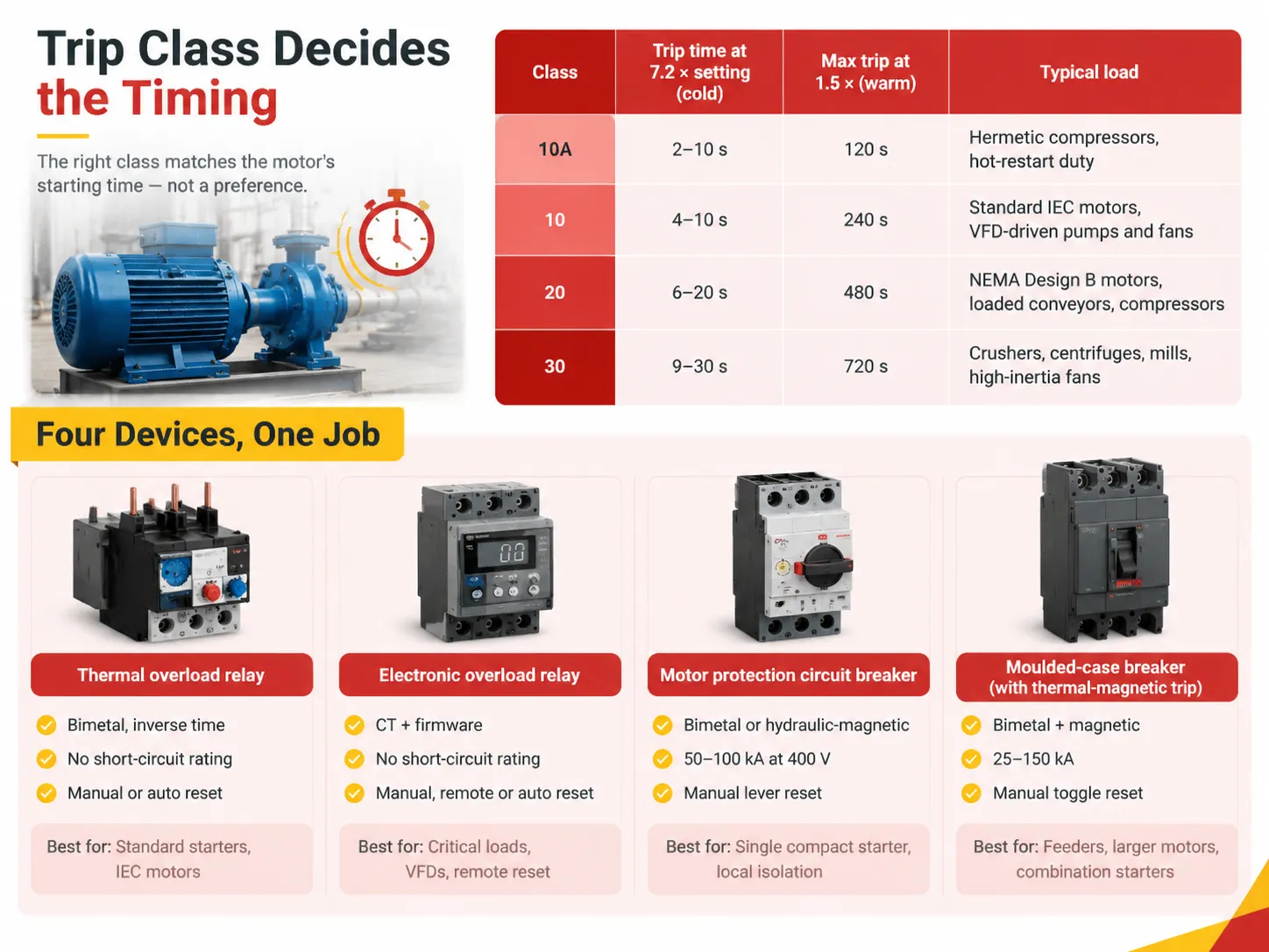
The class number is defined in IEC 60947-4-1 as the maximum trip time expressed in seconds at a factor of 7.2 of the trip current from a warm condition. The same standard stipulates an upper limit of 1.05 times, such that the relay cannot trip and a lower limit of 1.2 times such that the relay must trip in no more than two hours.
| Class | Trip time at 7.2 × setting (cold) | Max trip at 1.5 × (warm) | Typical load |
|---|---|---|---|
| 10A | 2–10 s | 120 s | Hermetic compressors, hot-restart duty |
| 10 | 4–10 s | 240 s | Standard IEC motors, VFD-driven pumps and fans |
| 20 | 6–20 s | 480 s | NEMA Design B motors, loaded conveyors, compressors |
| 30 | 9–30 s | 720 s | Crushers, centrifuges, mills, high-inertia fans |
Making a selection of the class is always dictated by the starting time and does not depend on personal preference. A pump receiving Class 10 is correctly classified when it runs at full speed in just three seconds. Conversely, a 200 kW centrifugal fan that takes 25 seconds for reaching maximum speed will require Class 30 so as not to cause the relay to tripp as its started in the normal conditions and the operator will need to turn the dial for disabling the protection system.
This logic can be applied to the case of motor circuit protectors and moulded-case breakers. These devices may not be used instead of each other in starters. There are motor circuit protectors that work with the magnetic principle only and come without having the thermal element incorporated that means that no thermal protection can be carried out. The differences are set out in this comparison of a motor circuit protector against a circuit breaker, and they matter when you are ordering a starter from a bill of materials written by somebody else.
The Four Devices That Do This Job
| Device | Overload element | Short-circuit rating | Reset | Best fit |
|---|---|---|---|---|
| Thermal overload relay | Bimetal, inverse time | None, needs backup | Manual or auto | Standard starters, IEC motors |
| Electronic overload relay | CT plus firmware | None, needs backup | Manual, remote or auto | Critical loads, VFDs, remote reset |
| Motor protection circuit breaker | Bimetal or hydraulic-magnetic | Included, typically 50–100 kA at 400 V | Manual lever | Single compact starter, local isolation |
| Moulded-case breaker with thermal-magnetic trip | Bimetal plus magnetic | Included, 25–150 kA | Manual toggle | Feeders, larger motors, combination starters |
See what is missing from the table? There is no one of these four options that is better than another. A thermal relay surveys for $25 and performs one function and does it with no firmware versioning. The motor protection circuit breaker has a price of three times the thermal relay and does away with the short-circuit detection component, as well as the wiring. All of it results in smaller panels and simpler assembly for a 500-motor project.
How the Devices Differ in Practice
Thermal relays are not reliable. The bimetal deteriorates, and the calibration may change by several percent over a time period of ten years. For example, when the relay was new, it had a limit of 1.15, but after 8 years in the hot environment of the cabinet, it is likely to change to 1.30. It is common practice to check the thermal relay once a year by introducing 1.5 times the current. This check takes around ten minutes per relay with the proper test device.
Electronic relays are much better in keeping the calibration and offer extras that solve real problems. The thermal memory feature of electronic relays prevents the restarting and retrying cycle that damages the windings. The phase-loss detection capability enables electronic relays to capture the most harmful overload possible for the motor since kicking on two phases, the motor will draw about 1.7 to 2 times the ten-pole power in the remaining windings while the third is not active, and a simple three-bimetal relay will be too slow because only 2 elements can be heated.
As for contactors, there is no point in outrunning the relay if the contactor does not survive the task. HUYU’s EXC7 AC contactor is rated for AC-3 motor duty with the utilisation category printed on the nameplate, and matching that category to the actual switching task is a bigger deal than matching the amp rating, which is the number most buyers compare.
Matching the Device to the Load
Fans and pump systems which start unloaded are straightforward case; Class 10, nameplate FLA with the use of ambient compensation is sufficient.
Conveyors and screw compressors run loaded but start against torque. Class 20 is applicable for a NEMA motor having 1.15 service factor. In this case the setting is at nameplate FLA when the motor is loaded during normal operating mode.
Submersible pumps, hermetic refrigeration compressors and all VFD-driven systems start with play of Class 10 or 10A. VFD limits starting current, making overload relay protect against slow thermal event rather than starting; faster class grants better winding protection without nuisance trips.
Crushers, mills and large induced draft fans have significant amount of rotating mass, so it takes 20 to 60 seconds for acceleration. Class 30 exists for such processes.When the load is genuinely this heavy, the failure mode to watch is not the trip but the contactor holding a stalled motor at locked-rotor current for a minute at a time, and the symptoms of that abuse show up long before the motor fails, as this guide to contactor failure symptoms describes.
Setting the Dial: The Numbers That Matter
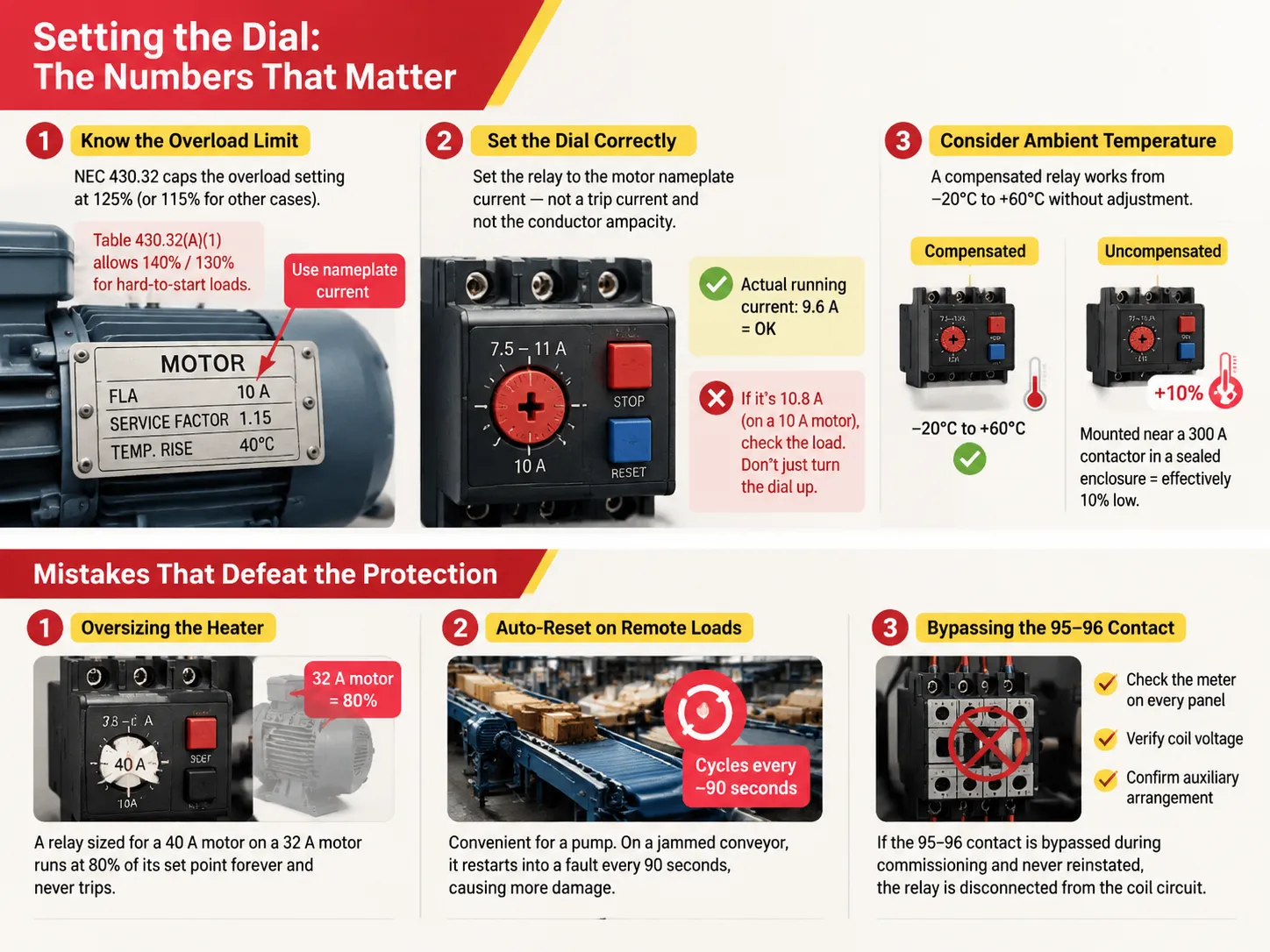
NEC 430.32 restricts overload settings to 125% of a motor’s rated full-load current for motors that have either a temperature rise of 40°C or less or a service factor of 1.15 or more. Otherwise, the limit is set at 115%. According to Table 430.32(A)(1), 140% and 130% can be utilized, respectively, where the motor will not start at the lower setting.
Set the dial to the nameplate current of the motor as opposed to the trip current and the ampacity. A 7.5–11 A relay set at 10 A would not trip at 10.5 A but would trip at 12 A within two hours. For example, if a clamp meter measures the running current to be 9.6 A, the setting is good and shows no need for further adjustments. If the reading is 10.8 A, indicating a problem with the load, simply increasing the dial reading to 12 A will lead to further complications.
The setting for ambient temperature takes its place second. A compensated relay will be able to work within a range of −20°C to +60°C without being adjusted. An uncompensated relay installed next to a 300 A contactor would have been set 10% low and compensatory adjustments would have been made by simply turning the dial up, which is not the right way to correct the setting.
Mistakes That Defeat the Protection
The frequent mistake is using a heater that is too large. When a relay that is designed for a motor that consumes 40 A works together with a device that needs 32 A, it operates at 80 % of the correct level and does not turn off, which means that it does not provide protection until the drive coil has burned out.
The other issue is self-resetting devices used for remote equipment. While using self-resetting devices on a pump that goes off once a season is fine, having them activate every 90 seconds with jammed conveyor makes the situation worse than with the jam itself.
Furthermore, people often bypass the 95–96 contacts during installation because the starter is failing to latch into position and do not even turn it back on after that. Although the relay has been properly calibrated, it does not work properly anymore. It is advisable to check the system every now and then to make sure that the overload protection is not connected to the faulty coil and testing the system with a meter is not a bad idea either.
FAQ
Is overload protection the same as surge protector?
No, nor can be used interchangeably. A surge protector grabs a transient voltag spike which takes place over microseconds and does not deal with current at all. Overload protection acts after being exposed to sustained overcurrent over seconds or minutes. A panel can and usually does need both, and the way they interact in a service entrance is covered in the comparison of a circuit breaker versus a surge protector.
What is the simplest form of overload protection?
A thermal overload relay consists of a bimetal element that is connected in series with the contactor coil through the 95-96 contact. There are two wires for input and output each, as well as the current setting knob and a manual reset button. It does not require any auxiliary power source or configuration, which is why it continues to be a first choice for general-purpose starters.
What does “no overload protection” mean?
It suggests the circuit is shielded solely from short circuits and ground faults. A magnetic breaker or a group of fuses will keep a motor running at 150% of its rated current continuously since 150% is quite a distance from the magnetic tripping point. Unfortunately, the motor will fail, but it will fail thermally rather than dramatically.
What does an overload protector do?
It monitors the electric current, simulates the heat generated in the winding of the motor electric motor circuit, and disconnects the control circuit when the heat exceeds the limit of the winding. The output action does not involve tripping the main contacts but only dropping the coil of the contactor, thus the overload contact is wired into the control circuit rather than the power circuit.
References
- ABB — Motor Starting and Protection Portfolio
- Rockwell Automation — Allen-Bradley Motor Control
- NFPA 70 — National Electrical Code, Article 430
- UL 508 — Industrial Control Equipment
- Electrical Engineering Portal — Motor Protection Reference
Conclusion
Thermal overload protection is considered to be a hardware component. The device has to be able to withstand a 600% startup current and must be able to respond to the load growing more than 40% above normal within seconds. The class number indicates the patience of the device while the current dial indicates what is considered normal and NEC 430.32 indicates the upper limits for both.
If these three are correct, the device almost does not matter. If, however, these three parameters are wrong, the most expensive relay will not protect at all, which is the occurrence that cannot appear on diagrams even in cases when the panel is fully equipped with 95–96 properly rated and set contacts.