
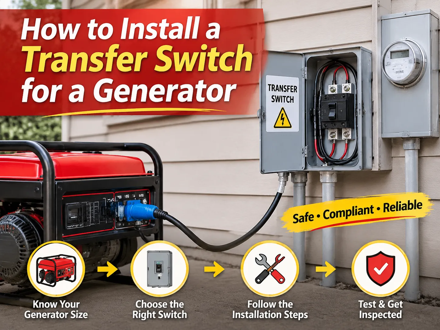
Cada invierno, hay alguien en una casa sin calefacción que mira fijamente el panel, echa un vistazo hacia el generador en el garaje y se pregunta si es suficiente con conseguir un cable y dos pinzas de cocodrilo. No es suficiente, y la justificación no es la documentación. La razón es que la retroalimentación del panel coloca voltaje del generador en el lado del usuario de la instalación, lo que hace posible que un operario de línea que llega para restaurar la red se encuentre con él. Por eso existe un interruptor de transferencia, y por qué la instalación gira en torno a un problema básico: cómo asegurar que el lado del usuario del generador y la red nunca puedan conectarse físicamente, y cómo establecer eso.
El conjunto de requisitos que se presenta a continuación se basa en la suposición de que el circuito en cuestión es un circuito monofásico que opera en Norteamérica y que utiliza un generador portátil o de reserva. La secuencia es bastante deliberada; el proceso de dimensionamiento es el primer paso, ya que impacta en todas las demás acciones que se realizan posteriormente, luego se pasa al trabajo mecánico, y después a los conductores, neutro y puesta a tierra, que inesperadamente resultan ser decisiones importantes que un número sorprendente de personas deja para que el inspector las resuelva.
Se requiere que un interruptor de transferencia tenga una clasificación igual o superior a la salida de su generador y debe contener el cableado del tamaño adecuado para esa clasificación y estar instalado de manera que la corriente de suministro de energía de la red y las corrientes de capacidad del generador no se combinen en un punto. Por ejemplo, el generador portátil de 10,000 W producirá una salida de aproximadamente 41.7 A a 240 V, por lo que es recomendable comprar un interruptor de 50 A y cableado de cobre AWG 6. Los costos del hardware en el caso de interruptores manuales pre-cableados varían entre $400 y $800, mientras que un kit de bloqueo con licencia puede costar entre $50 y $150. Los costos adicionales incluirán el trabajo de electricistas, que se estima entre $300 y $600, y permisos. La instalación puede dividirse en cuatro operaciones mecánicas y tres eléctricas: selección de circuitos, instalación del interruptor, instalación de la caja de entrada y tendido de cables, conexión de alimentación de la red y conexión de alimentación del generador después de que se haya realizado la prueba. La sección sobre el neutro debe leerse primero ya que representa el lugar donde las consideraciones relacionadas con este trabajo fallan más.
Qué Interruptor de Transferencia Necesita Realmente
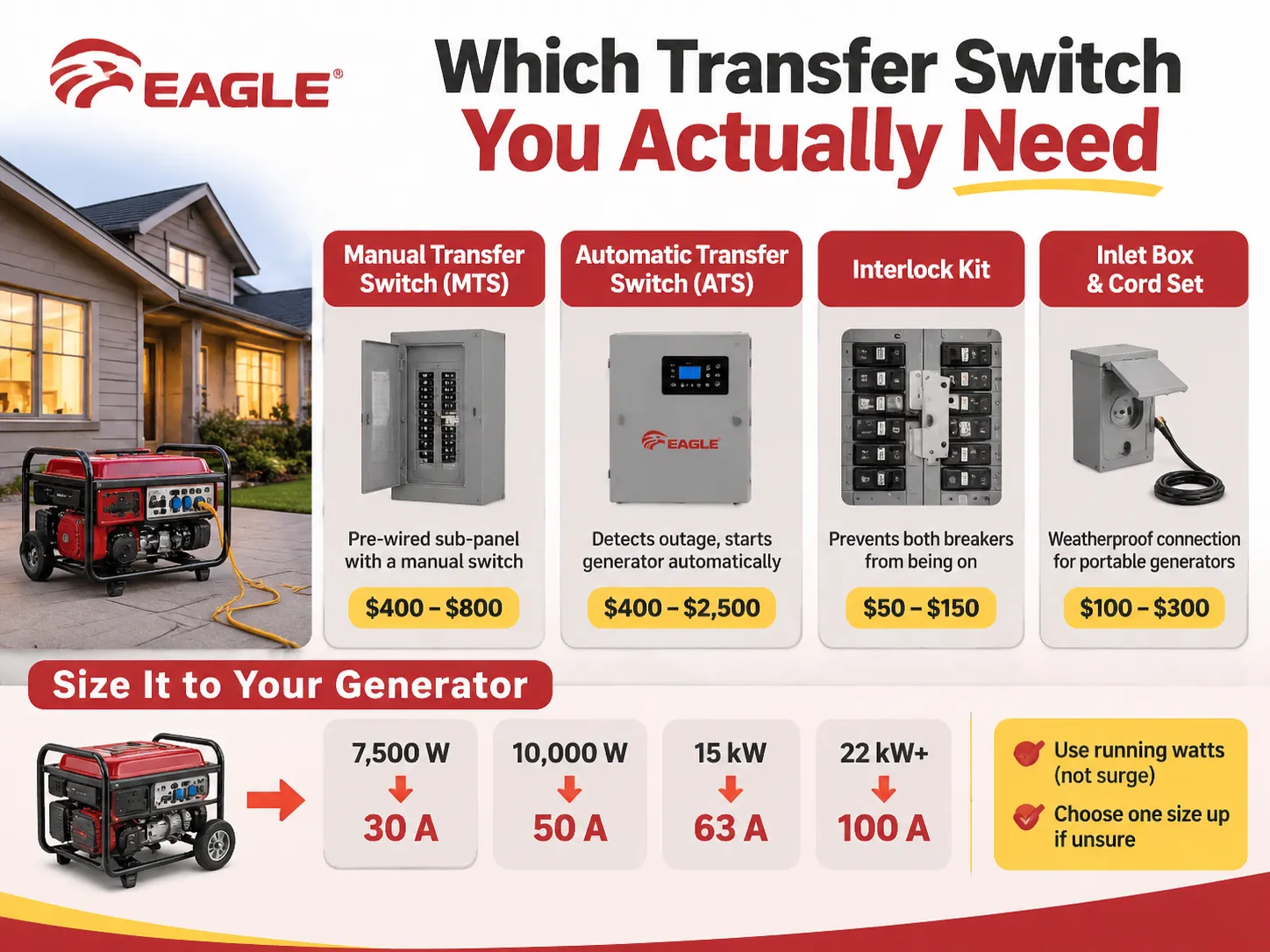
Se identifican cuatro tipos de dispositivos como interruptores de transferencia, y no pueden usarse en lugar de los otros. Su elección aquí dependerá de si tiene un generador portátil o fijo, si habrá alguien en casa en el momento del corte de energía, y el tamaño de la casa que necesita ser alimentada.
| Producto | Costo del hardware | Lo que hace | Ajustes |
|---|---|---|---|
| Interruptor de transferencia manual (MTS) | $400 a $800 | Subpanel pre-cableado con de 6 a 16 circuitos ramales y un mecanismo de dos posiciones que se acciona manualmente | Generadores portátiles, propietarios presentes durante los cortes |
| Interruptor de transferencia automático (ATS) | $400 a $2,500 | Detecta la pérdida de la red, arranca el generador, transfiere la carga, retransfiere y enfría al restaurarse la red | Generadores de reserva con un controlador de arranque de dos cables |
| Kit de enclavamiento | $50 a $150 | Una placa deslizante listada que impide que el interruptor principal y el del generador estén activados simultáneamente | Paneles modernos con dos espacios libres adyacentes, cobertura para toda la casa |
| Caja de entrada y juego de cable | $100 a $300 | El punto de conexión resistente a la intemperie en la pared exterior, más el cable hacia el generador | Cada instalación portátil, junto con una de las anteriores |
En contraste con un dispositivo eléctrico, un interruptor debe ser un subpanel, y esa distinción debe hacerse en el mostrador. Vendrá con sus propios interruptores, un conjunto de cables instalados de fábrica, y el instalador transferirá los circuitos derivados adecuados desde el panel principal hacia él. Gama de interruptores manuales de transferencia clase PC muestra la construcción: dos posiciones de ruptura enclavadas, una carcasa común y capacidad de terminales para las alimentaciones tanto de la red como del generador. Un kit de enclavamiento cumple la función opuesta. De hecho, no añade nada al conteo de circuitos; simplemente hace que el panel sea seguro, por lo que funciona muy bien en una casa donde el generador es lo suficientemente grande para alimentar todo.
Dimensionamiento del interruptor según el generador, no según el panel
La clasificación de amperaje se determina dividiendo la potencia continua del generador entre 240 voltios. Una máquina de 10 kW produce 41.7 A, lo que corresponde a un interruptor de 50 A. Un generador de 7.5 kW produce 31.3 A para un interruptor de 30 A, mientras que un generador de 12 kW produce exactamente 50 A, siendo este el límite superior de las unidades móviles populares.
Al calcular el amperaje, use estas dos reglas: se utilizan los vatios en funcionamiento y nunca los vatios de arranque, ya que el interruptor está clasificado para carga continua. Nunca subestime el interruptor, ya que un interruptor de 30 A en un generador de 50 A solo limitará la salida del generador, haciendo innecesarias las conjeturas sobre la operación del generador. Elegir un interruptor con una clasificación más alta no causará daño; sin embargo, elegir uno con una clasificación más baja será contrario al sentido común.
Por encima del rango portátil, la aritmética cambia. Una unidad de 15 kW necesita un dispositivo de 63 A a 240 V, que es la banda de tamaño donde el interruptor automático de transferencia de 63 A se encuentra, y un generador de reserva para toda la casa de 22 kW pasa a un interruptor con clasificación de servicio de 100 A. Más allá de ese punto, el interruptor está clasificado para el servicio, no para la máquina, porque se inserta entre el medidor y el panel principal.
Herramientas y materiales antes de comenzar
Los instrumentos son normales con una excepción. Se requiere un destornillador de torque. El valor de torque está indicado en las terminales de los interruptores y los interruptores de transferencia, y usualmente una terminal floja causa la falla después de algún tiempo.
Destornilladores aislados, de punta cuadrada, pelacables clasificados para 6 AWG, destornillador de torque en libra-pulgadas, probador de voltaje bipolar (recuerde que el destornillador neón no es el probador), lápiz de voltaje sin contacto, cinta pasacables, taladro con sierras para penetrar la pared y un teléfono para tomar fotos antes y después del trabajo también deben estar en su conjunto de herramientas. Las fotos no pueden considerarse simplemente como imágenes. Son la prueba de la correcta puesta a tierra y unión cuando se instala la cubierta.
Materiales: interruptor, caja de entrada clasificada NEMA 3R en caso de que se instale en el exterior, cuatro cables del calibre regulado, conducto y accesorios, interruptor bipolar para el suministro eléctrico, sellador para exteriores, etiquetas, cable de generador de longitud suficiente. Los kits generalmente vienen con un cable de 10 pies, que resulta ser demasiado corto considerando que el generador se instala lejos de la casa y el escape va hacia el lado opuesto.
Paso 1 a Paso 4: Permiso, Aislamiento, Circuitos y Montaje
- Paso 1. Obtenga una aprobación previa. Casi todos los municipios requieren que obtenga un permiso eléctrico junto con una inspección del interruptor de transferencia, que generalmente cuesta entre $50 y $300. Es más rentable obtener su permiso primero que después de completar todo el trabajo. En algunas jurisdicciones, las inspecciones no se pueden programar retroactivamente en absoluto.
- Paso 2. Desconecte y verifique. Apague primero su interruptor principal. Después de eso, use un probador bipolar para verificar los terminales. Probar en el panel mientras su interruptor principal está apagado indica el estado de funcionamiento de su interruptor principal, pero no significa que sus bornes estén seguros si algo le sucede a su interruptor principal o hay otra fuente de energía.
- Paso 3. Seleccione circuitos. Al usar un interruptor manual, puede conectar entre 5 y 16 circuitos. Debe hacer una lista precisa que incluya solo aquellos dispositivos que necesitan estar conectados cuando se trabaja. Cuente dos cargas si son de 240 voltios. No caiga en la trampa de incluir su estufa y secadora, ya que es imposible que los generadores portátiles operen estos dispositivos.
- Paso 4. Instale el interruptor. Debe posicionarlo cerca del panel principal para que las corridas de conducto sean cortas. La falta de espacio debajo del gabinete o la longitud incorrecta del cable es un problema de código que necesita una solución adicional. También debe montar el interruptor nivelado.
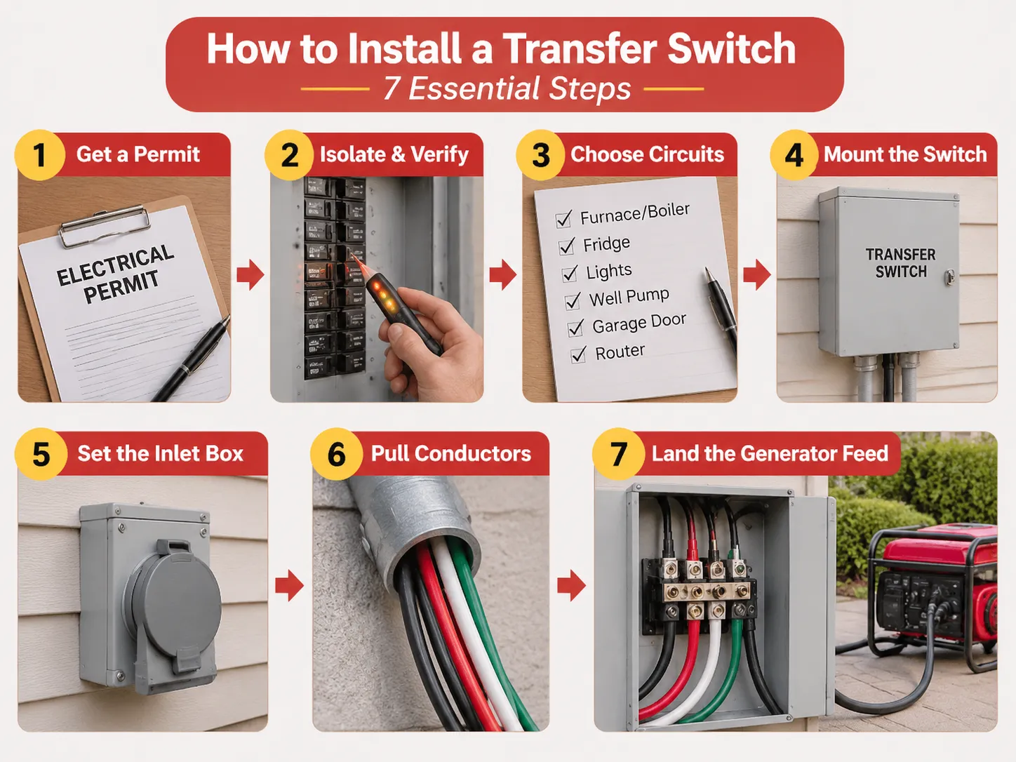
Paso 5 a Paso 7: Conducto, Conductores y la Caja de Entrada
- Paso 5. Fije la caja de entrada en posición. Idealmente, la caja debe colocarse en una pared exterior, no muy lejos de donde se instalará el generador. La altura también debe elegirse para que no haya nieve ni agua estancada sobre el cable. La entrada NEMA 14-50R proporciona dos cables calientes, uno neutro y una conexión a tierra. El otro tipo común de entrada es la CS6375, la que elija dependerá del enchufe del generador. Elegir la incorrecta le obligará a comprar otra entrada o un adaptador. En cualquier caso, los adaptadores de 50A no son favorables en un ambiente húmedo.
- Paso 6. Introduzca los conductores. Para el sistema de 50 A, se requieren cuatro conductores de cobre 6 AWG: uno negro, uno rojo, uno blanco y uno verde. Los conductores de cobre 6 AWG pueden transportar de manera segura 65 A a una temperatura de 75 °C. Por lo tanto, se puede decir que la caída de voltaje a lo largo de un conductor para una longitud de 50 pies es aproximadamente 2 %, dentro del 3 % permitido de caída de voltaje en el alimentador. El cable NM-B no puede usarse dentro de un conducto exterior o en un área húmeda; por lo tanto, se debe usar THHN o XHHW en un conducto. El tamaño del conducto debe ser apropiado para la cantidad de conductores utilizados, permitiendo un fácil tendido.
- Step 7. Land the generator feed from the generator to the hot bar. The generator feed making the hot, neutral and ground connections. Once these connections have been made, conduct the utilities connection from the two-pole breaker in the main panel. The two connections should be kept separated in the enclosure. The conductors should be dressed to avoid crossing of moving contacts.
Wiring the Switch: Utility Side, Generator Side, and the Breaker That Feeds It
The utility side comes from a new two-pole breaker in the main panel, sized to the switch rating. For a 50 A switch that is a 50 A two-pole breaker, and a standard thermal-magnetic device of the kind in this 63 A miniature circuit breaker range is what the circuit expects: 6 kA or 10 kA interrupting capacity, C curve for mixed loads, and a torque value that has to be honoured on both lugs.
The generator-side voltage-derived comes into the inlet box. Within a manual switch, there are two breaker positions for each branch circuit: one fed from the utility bus and the other, in turn, fed from the generator bus. And the mechanism ensures that only one bus is energized at any time. This is the whole trick, and it is mechanical-as opposed to electronic-in nature. There’s no way to bypass it with a software bug or a stuck relay.
Within an automatic switch, the logic is contrary. A controller would monitor both sources, start the generator, wait for the frequencies and voltages to stabilize, and then activate the motor-operated mechanism. This transfer is temporarily delayed for two reasons: first, an accelerating generator produces low voltage at low frequency, and closing onto a load at this time causes failure of compressor motors; second, a changeover is put on hold for a second reason, which lies in order that the utility can settle down before handing back the house.
The Neutral Question That Fails More Inspections Than Anything Else
There are two valid ways to manage the neutral, and making the incorrect choice will lead to either shock risks or nuisance trips.
- Solid neutral, non-separately derived. The neutral of the generator and that of the utility are linked at the switch, while the generator frame remains bonded as part of the same grounding system. In this configuration, the generator’s neutral has to be unbonded from the frame, as the presence of two separate bonds in the system results in neutral current going through the ground conductors. That is the most common setup for portable generators feeding an isolation switch.
- Switched neutral, separately derived. When the switch disconnects the neutral together with hots, the generator becomes a separately derived system, and the neutral is bonded either at the generator or switch while having the grounding electrode conductor going to the grounding system of the building. This arrangement is used in much larger stationary setups and for switches rated for the service.
- The failure mode assumes the use of a portable generator with a bonded neutral in a solid neutral switch. In that case, it results in parallel neutral paths, ground current, and nuisance tripping of GFCI devices every time the generator is on. Look for the instructions that specify whether the generator neutral is bonded, examine the switch instructions for the arrangement suitable for this case, and note what you’ve found. If the two instructions contradict each other, you’ll have to do something minor yet specific to fix this issue.
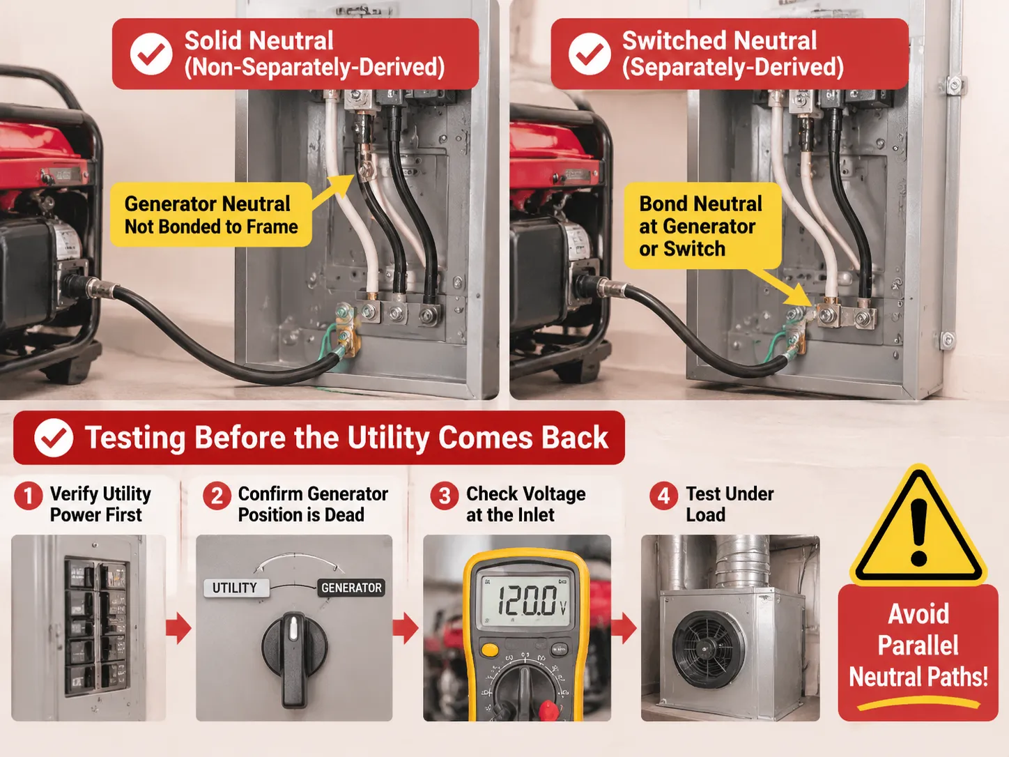
Testing Before the Utility Comes Back
To ensure your safety while testing, you should start with resetting the generator by disconnecting it from the system and then checking power on the utility panel. This will show whether there is any voltage present on circuits being backed up. Following that, plug the generator in and see if there is no power in the same circuits.
After that, you will have to start the generator outside, then connect the cord and check voltage before switching on the generator. You should expect reading of 240V between the two hot phases, 120V on hot vs neutral and 120V on hot vs ground. When the neutral is missing, you will read 120V on hot vs ground and some strange voltage on hot vs neutral.
After that you have to switch to the generator and start checking the loads on circuits one by one from the highest power draw unit in each of the circuits. The best way to test the system would be to start a furnace fan. The key point here is taking the voltage when all the load is connected.
What the Job Actually Costs
The cost of the hardware for a 10-circuit manual transfer switch with an inlet and cable ranges from $500 to $900. In an installation of a manual transfer switch that has been prewired, the labor customary to be about from 2 to 4 hours, which will be costing roughly around $300 to $600. Adding the cost of the permit will bring the total to around $850 to $1,800 for the simplest of installations.
Interlock kits are relatively cheaper as compared to the previous options. The cost of interlock kits is from $50 to $150 and that of the electrician is about $150 to $400 as the task involves placing only one circuit breaker and a faceplate. You can also find expensive automatic whole house switches that may cost you $800 to $2,500 as the switch alone will take a longer period to install. For scale at the larger end, the pricing structure on a 600 A four-pole service entrance automatic transfer switch shows how quickly switchgear pricing moves once the device becomes service-rated.
Mistakes That Get Installations Redone
Double male cord. Using a cord with both ends being a male plug to connect generator to dryer outlet is the most hazardous shortcut in the industry. It backfeeds the panel and energizes service conductors, which may kill utility personnel or damage the generator when the grid goes back online. In addition to this, it is against code everywhere, and no inspector will let it go.
Undersized conductors. A 50 A switch fed using 10 AWG wire simply because it happens to be available on the truck. Even though the breaker does its job, the wire overheats, and the failure can take place months later.
Generator placed too close to the house. The total number of fatalities due to carbon monoxide poisoning in America reaches about 100 each year, and nearly 80% of those happen in domestic settings. So, the generator must be kept outside, at a considerable distance from the doors and windows, exhaust pointing away from the house and a battery-powered CO alarm operating on all floors.
No load calculation. When the generator is connected to a switch with many circuits that cannot be supported by the generator, the breaker will trip at the first cold night. So, the watts for all devices must be calculated to avoid any problem.
Unmarked circuits. A panel directory made with a pencil and never updated can create a problem during the blackout that happens in the middle of the night. It is recommended to print the panel directory so there is a copy available when needed.
Manual or Automatic: Which One Belongs in Your House
Manual switches are based on the premise that the individual is in the house, awake, and able to venture out into inclement weather. This is acceptable for most homes and outages, which last hours rather than days. However, manual switches fail houses with wet basements containing a sump pump, people with medical conditions, or an owner on the move.
On the other hand, automatic switches operate on the understanding that a generator is permanently installed and supplied with a start signal, has been provided with enough fuel to run for several days, and has a functioning exercise regimen. The 100 A automatic transfer switch is the size band that suits a service-rated residential installation, with adjustable transfer and retransfer delays so the generator is not asked to accept load before it is ready.The trade is legit: an ATS costs about 2 to 4 times more than a manual switch plus required equipment like a battery, controller and yearly service costs. In exchange you get lights without needing to leave bed.
A practical way could help reduce costs. You could set a large manual switch and leave space in the box for a controller later on. Panel and input costs are usually high, and it is easy to change a mechanism later.
Preguntas Frecuentes
Can I install a generator transfer switch myself?
In various localities it is possible for a resident to apply for an electrical permit for installation on their personal single-family house and perform the necessary work pending inspection. It is the conditions that are important rather than the permission: the panel should be turned off, the wires should be of adequate size, the neutral connection should correspond to the one on the generator, and the installation should be performed properly. If anything in those four requirements is questionable, then the answer should be ‘no’. Interlocking kits are the easiest choice for DIY enthusiasts, but still need to be certified and compatible with the given model of the electrical panel.
How much does it cost to put in a generator transfer switch?
If you’re purchasing a hard-wired 10-circuit manual switch, your hardware expenses will generally fall in the range of $400 to $800, while installation by an electrician will run between $300 and $600. Permits will often cost from $50 to $300, for a total installed cost of between approximately $850 and $1,800. Interlock kits run from $50 to $150 in parts and from $150 to $400 for installation. A whole-house automatic switching mechanism for the use of a standby generator runs from $800 to $2,500, with the actual cost of installing such a switch higher, since service conductors and wiring for the control of the generator are necessary. An inlet box and a long enough cord often add about $100 to $300 to the installation estimate, but are sometimes left out.
Can a homeowner install a generator transfer switch?
Often, the permit is the determining aspect, and not really the talent. Some municipal building departments allow owner-permit electrical work on an owner-occupied single-family dwelling and with the inspection; a very few require a licensed electrician to do anything that is considered to take place inside of the service panel. Be sure to call the authority having jurisdiction before you buy anything hardware-wise, since that is going to change the picture entirely. Note as well that the unpermitted installation could be enough for the insurer to deny a fire claim which is in fact much larger than the amount you saved on labour.
What size transfer switch do I need for a 10,000 watt generator?
The switch is rated for 50 A. The calculation of operating wattage divided by 240 V yields the result of 10,000 ÷ 240, which is 41.7 A. The next standard size switch is, therefore, 50 A. Only operating wattage should be considered and not starting wattage since a switch operates continuously on the same current. A 50 A switch requires six AWG wires made of copper material and a double pole 50 A breaker on the utility side. If the generator outlet is 30 A L14-30 versus 50 A 14-50 then both switch and inlet have to match the outlet and the generator will be limited by the socket.
Do I need a transfer switch if I only use extension cords?
No, and that is the only legally permissible option. Instead of wiring the generator into your house system, extension cords are used to connect the generator with an appliance, thus making the generator independent of the house wiring which prevents any backfeed. This means convenience and safety: runners through the doors, no fixed electrical loads such as contacting pumps or a furnace, and clogged path with obstacles in the dark. The minute you need to use electricity in a fixed installation, you must use a transfer device according to NECA702.
Referencias
- Electrical Engineering Portal — Installing a Manual Transfer Switch
- NFPA — National Electrical Code, Article 702 Optional Standby Systems
- Generac — Home Standby and Transfer Switch Products
- Reliance Controls — Manual Transfer Switch and Inlet Box Systems
- ASCO Power Technologies — Automatic Transfer Switch Engineering
Conclusión
Installing the generator system is easy. The tough part is deciding. Size from running watts, keep switched and inlet matched to generator output and establish the neutral before pulling the first wire because that’s what fails inspection and puts current where it should not go.
Then buy hardware only once. A switch rated one size above your generator will cost only a bit more and will never let you down; a switch that is rated one size below will ruin the generator you already have. If you tell us what your generator’s continuous rating is, its outlet and whether or not its neutral is bonded we will tell you which board and which pole configuration you need for the job.