
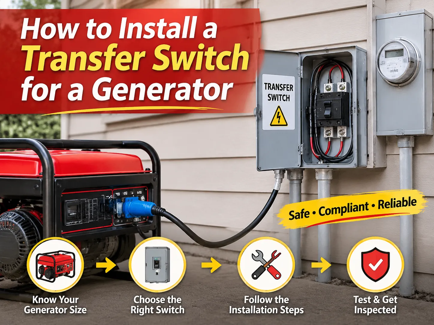
Chaque hiver, il y a quelqu’un dans une maison non chauffée qui fixe le tableau, jette un coup d’œil vers le générateur dans le garage, et se demande si un câble et deux pinces crocodiles suffisent. Ce n’est pas suffisant, et la justification ne repose pas sur la paperasse. La raison est que le retour d’alimentation vers le tableau place la tension du générateur du côté utilisateur de l’installation, ce qui peut mettre en danger un technicien de réseau arrivant pour rétablir le réseau. C’est pourquoi il y a un commutateur de transfert, et pourquoi l’installation tourne autour d’un problème fondamental : comment garantir que le côté utilisateur du générateur et le réseau ne puissent jamais être connectés physiquement, et comment le vérifier.
L’ensemble des exigences ci-dessous est basé sur l’hypothèse que le circuit en question est un circuit monophasé fonctionnant en Amérique du Nord et qu’il utilise un générateur portable ou de secours. La séquence est tout à fait délibérée ; le processus de dimensionnement est la première étape, car il impacte toutes les autres actions entreprises ultérieurement, puis vient le travail mécanique, puis les conducteurs, le neutre et la mise à la terre, qui s’avèrent être des décisions importantes que beaucoup de personnes laissent étonnamment à l’inspecteur.
Un commutateur de transfert doit avoir une capacité égale ou supérieure à la sortie de votre générateur et doit contenir un câblage de taille appropriée pour cette capacité, installé de manière à ce que le courant d’alimentation du réseau et les courants de capacité du générateur ne se combinent pas en un seul point. Par exemple, un générateur portable de 10 000 W produira une sortie d’environ 41,7 A sous 240 V, il est donc conseillé d’acheter un commutateur 50 A et un câblage cuivre 6 AWG. Les coûts du matériel dans le cas de commutateurs manuels pré-câblés varient entre $400 et $800, tandis qu’un kit d’interverrouillage agréé peut coûter entre $50 et $150. Les coûts supplémentaires incluent le travail des électriciens, estimé entre $300 et $600, ainsi que les permis. L’installation peut être divisée en quatre opérations mécaniques et trois électriques : sélection des circuits, installation du commutateur, installation de la boîte d’entrée et tirage des câbles, raccordement de l’alimentation réseau et du générateur après réalisation du test. La section concernant le neutre doit être lue en premier car elle représente le point où les considérations liées à ce travail échouent le plus souvent.
Quel commutateur de transfert vous faut-il réellement
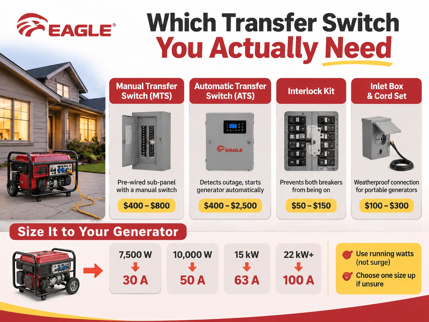
Quatre types d’appareils sont identifiés comme commutateurs de transfert, et ils ne peuvent pas être utilisés les uns à la place des autres. Votre choix dépendra de la nature de votre générateur (portable ou fixe), de la présence ou non de personnes à domicile lors de la coupure de courant, et de la taille de la maison à alimenter.
| Produit | Coût du matériel | Ce qu'il fait | Convient |
|---|---|---|---|
| Commutateur de transfert manuel (MTS) | $400 à $800 | Sous-panneau pré-câblé avec 6 à 16 circuits dérivés et un mécanisme à deux positions actionné manuellement | Générateurs portables, propriétaires présents lors des coupures |
| Commutateur de transfert automatique (ATS) | $400 à $2,500 | Détecte la perte du réseau, démarre le générateur, transfère la charge, retransfère et refroidit lors du rétablissement | Générateurs de secours avec un contrôleur de démarrage à deux fils |
| Kit d’interverrouillage | $50 à $150 | Une plaque coulissante homologuée qui empêche que le disjoncteur principal et celui du générateur soient activés simultanément | Tableaux modernes avec deux emplacements adjacents libres, couverture complète de la maison |
| Boîte d’entrée et jeu de cordons | $100 à $300 | Le point de connexion étanche sur le mur extérieur, plus le cordon vers le générateur | Chaque installation portable, en complément de l’un des éléments ci-dessus |
Contrairement à un appareil électrique, un interrupteur doit être un sous-tableau, et cette distinction doit être faite au comptoir. Il sera livré avec ses propres disjoncteurs, un jeu de câbles préinstallés en usine, et l’installateur transférera les circuits dérivés appropriés du tableau principal vers celui-ci. Gamme d’interrupteurs de transfert manuel de classe PC montre la construction : deux positions de coupure interverrouillées, un boîtier commun, et une capacité de bornier pour l’alimentation réseau et générateur. Un kit d’interverrouillage remplit la fonction opposée. Il n’ajoute en effet rien au nombre de circuits – il rend simplement le tableau sûr, ce qui explique son efficacité dans une maison où le générateur est suffisamment puissant pour alimenter l’ensemble.
Dimensionnement de l’interrupteur selon le générateur, pas selon le tableau
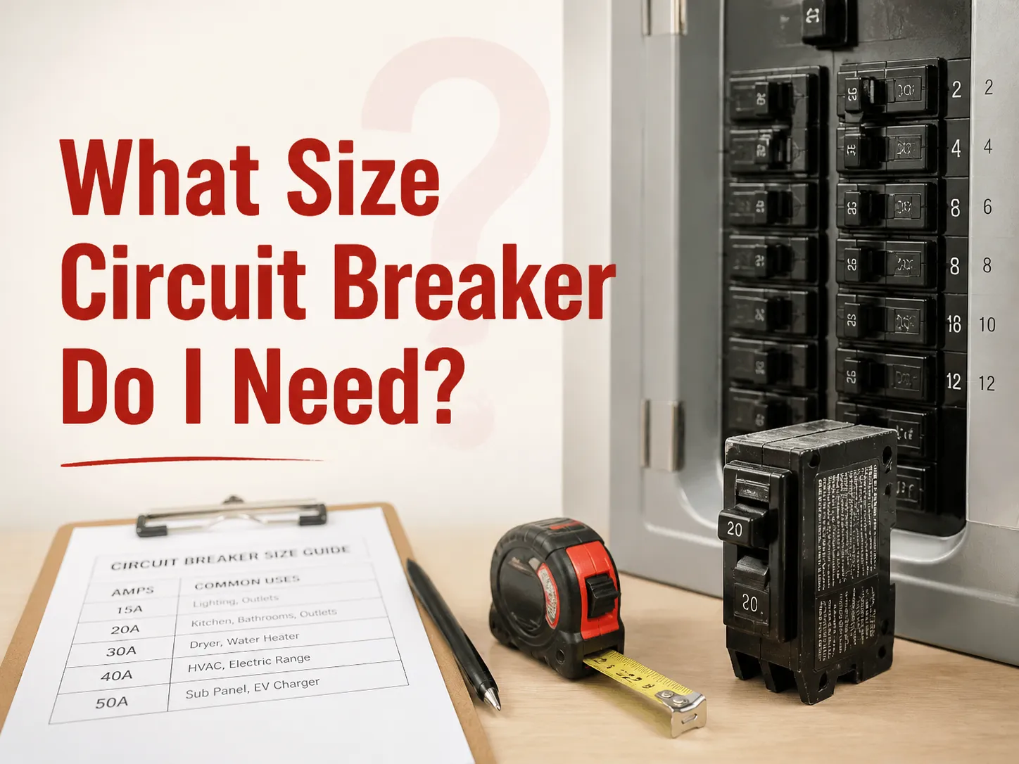
Le courant nominal est déterminé en divisant la puissance continue du générateur par 240 volts. Une machine de 10 kW fournit 41,7 A, ce qui correspond à un interrupteur de 50 A. Un générateur de 7,5 kW fournit 31,3 A pour un interrupteur de 30 A tandis qu’un générateur de 12 kW fournit exactement 50 A, ce qui constitue la limite supérieure des unités mobiles populaires.
Lors du calcul de l’ampérage, appliquez ces deux règles : utilisez la puissance en fonctionnement et jamais la puissance de démarrage, car l’interrupteur est dimensionné pour une charge continue. Ne sous-dimensionnez jamais l’interrupteur, car un interrupteur de 30 A sur un générateur de 50 A limitera simplement la sortie du générateur, rendant inutile toute estimation du fonctionnement du générateur. Choisir un interrupteur avec une capacité supérieure ne causera aucun dommage ; en revanche, choisir un interrupteur avec une capacité inférieure serait contraire au bon sens.
Au-delà de la gamme portable, le calcul change. Une unité de 15 kW nécessite un dispositif de 63 A à 240 V, qui correspond à la plage de taille où le commutateur de transfert automatique 63 A se situe, et un générateur de secours pour toute la maison de 22 kW passe à un interrupteur de service de 100 A. Au-delà de ce point, l’interrupteur est dimensionné selon le service, pas selon la machine, car il est inséré entre le compteur et le tableau principal.
Outils et matériaux avant de commencer
Les instruments sont normaux à une exception près. Le tournevis dynamométrique est requis. La valeur de couple est indiquée sur les cosses des disjoncteurs et des interrupteurs de transfert, et généralement une cosse desserrée provoque la défaillance après un certain temps.
Tournevis isolés, à empreinte carrée, dénudeurs de fils calibrés pour du 6 AWG, tournevis dynamométrique en inch-livres, testeur de tension bipolaire (rappelez-vous que le tournevis néon n’est pas un testeur), stylo de détection de tension sans contact, tire-fil, perceuse avec scies pour percer le mur, et un téléphone pour prendre des photos avant et après le travail doivent également faire partie de votre trousse à outils. Les photos ne peuvent pas être considérées simplement comme des images. Elles constituent la preuve de la mise à la terre et du raccordement corrects lorsque le revêtement est installé.
Matériaux : interrupteur, boîte d’entrée certifiée NEMA 3R au cas où elle serait installée à l’extérieur, quatre fils de calibre réglementé, conduit et raccords, disjoncteur bipolaire pour l’alimentation électrique, mastic d’étanchéité, étiquettes, câble de générateur de longueur suffisante. Les kits sont généralement fournis avec un câble de 10 pieds, ce qui s’avère trop court compte tenu du fait que le générateur est installé loin de la maison et que l’échappement se trouve du côté opposé.
Étape 1 à Étape 4 : Permis, Isolement, Circuits et Montage
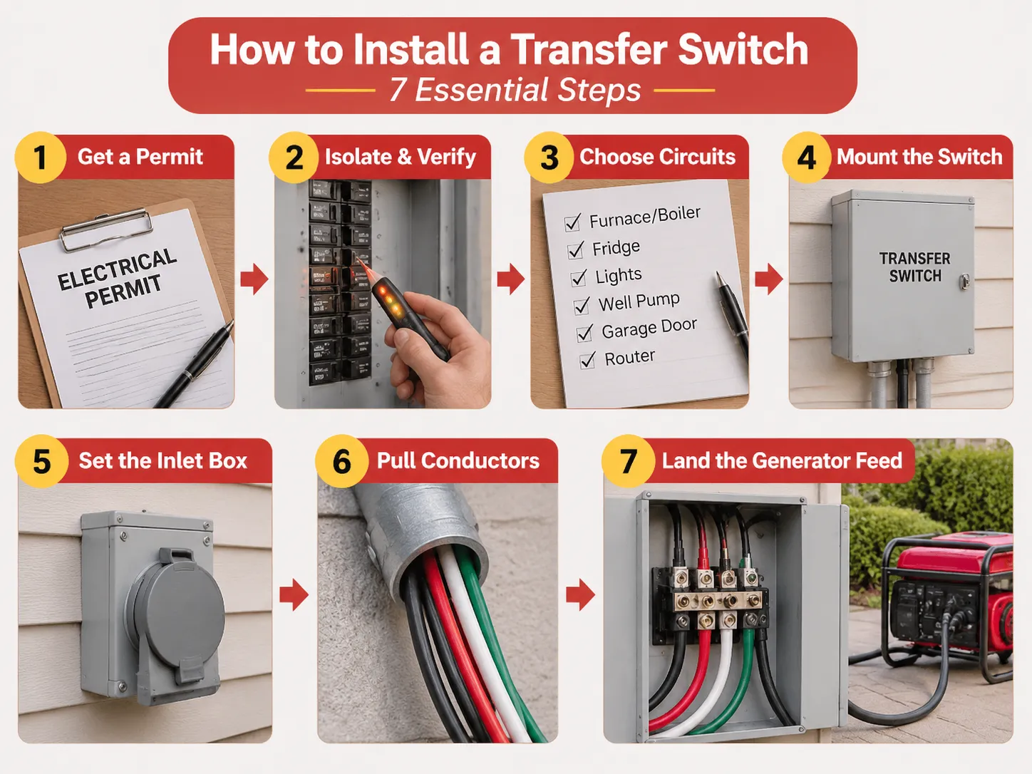
- Étape 1. Obtenez une approbation au préalable. Presque toutes les municipalités exigent que vous obteniez un permis électrique ainsi qu’une inspection du commutateur de transfert, qui coûte généralement entre 150 $ et 300 $. Il est plus rentable d’obtenir votre permis avant que tous les travaux soient terminés. Dans certaines juridictions, les inspections ne peuvent pas être programmées rétroactivement.
- Étape 2. Déconnectez et vérifiez. Coupez d’abord votre disjoncteur principal. Ensuite, utilisez un testeur bipolaire pour vérifier les bornes. Tester dans le panneau alors que votre disjoncteur principal est coupé indique l’état de fonctionnement de votre disjoncteur principal, mais ne signifie pas que vos cosses sont sûres si quelque chose arrive à votre disjoncteur principal ou s’il y a une autre source d’alimentation.
- Étape 3. Sélectionnez les circuits. Lors de l’utilisation d’un commutateur manuel, vous pouvez connecter environ 5 à 16 circuits. Vous devez établir une liste précise qui inclut uniquement les appareils devant être connectés en fonctionnement. Comptez deux charges si elles sont de 240 volts. Ne tombez pas dans le piège d’inclure votre cuisinière et votre sèche-linge, car il est impossible pour les générateurs portables de faire fonctionner ces appareils.
- Étape 4. Installez le commutateur. Vous devez le positionner près du panneau principal afin que les conduits soient courts. Le manque d’espace sous l’armoire ou une longueur de fil incorrecte constitue un problème de code nécessitant une résolution supplémentaire. Vous devez également monter le commutateur de niveau.
Étape 5 à Étape 7 : Conduit, Conducteurs et Boîte d’Entrée
- Étape 5. Fixez la boîte d’entrée en position. La boîte doit idéalement être placée sur un mur extérieur, pas trop loin de l’endroit où le générateur sera installé. La hauteur doit également être choisie de manière à ce qu’il n’y ait ni neige ni eau stagnante sur le câble. L’entrée NEMA 14-50R fournit deux fils chauds, un neutre et une connexion de terre. L’autre type courant d’entrée est le CS6375, celui que vous choisissez dépendra de la prise du générateur. Choisir le mauvais entraînera l’achat d’une autre entrée ou d’un adaptateur. Dans tous les cas, les adaptateurs 50A ne sont pas recommandés dans un environnement humide.
- Étape 6. Faites passer les conducteurs. Pour le système 50 A, quatre conducteurs en cuivre 6 AWG sont requis : un noir, un rouge, un blanc et un vert. Les conducteurs en cuivre 6 AWG peuvent transporter en toute sécurité 65 A à une température de 75 °C. Par conséquent, on peut dire que la chute de tension sur un conducteur pour une longueur de 50 pieds est d'environ 2 %, dans une chute de tension autorisée de 3 % sur le circuit d'alimentation. Le câble NM-B ne peut pas être utilisé à l'intérieur d'un conduit extérieur ou dans une zone humide, c'est pourquoi THHN ou XHHW doit être utilisé dans une gaine. La taille du conduit doit être appropriée au nombre de conducteurs utilisés, permettant un tirage facile.
- Step 7. Land the generator feed from the generator to the hot bar. The generator feed making the hot, neutral and ground connections. Once these connections have been made, conduct the utilities connection from the two-pole breaker in the main panel. The two connections should be kept separated in the enclosure. The conductors should be dressed to avoid crossing of moving contacts.
Wiring the Switch: Utility Side, Generator Side, and the Breaker That Feeds It
The utility side comes from a new two-pole breaker in the main panel, sized to the switch rating. For a 50 A switch that is a 50 A two-pole breaker, and a standard thermal-magnetic device of the kind in this 63 A miniature circuit breaker range is what the circuit expects: 6 kA or 10 kA interrupting capacity, C curve for mixed loads, and a torque value that has to be honoured on both lugs.
The generator-side voltage-derived comes into the inlet box. Within a manual switch, there are two breaker positions for each branch circuit: one fed from the utility bus and the other, in turn, fed from the generator bus. And the mechanism ensures that only one bus is energized at any time. This is the whole trick, and it is mechanical-as opposed to electronic-in nature. There’s no way to bypass it with a software bug or a stuck relay.
Within an automatic switch, the logic is contrary. A controller would monitor both sources, start the generator, wait for the frequencies and voltages to stabilize, and then activate the motor-operated mechanism. This transfer is temporarily delayed for two reasons: first, an accelerating generator produces low voltage at low frequency, and closing onto a load at this time causes failure of compressor motors; second, a changeover is put on hold for a second reason, which lies in order that the utility can settle down before handing back the house.
The Neutral Question That Fails More Inspections Than Anything Else
There are two valid ways to manage the neutral, and making the incorrect choice will lead to either shock risks or nuisance trips.
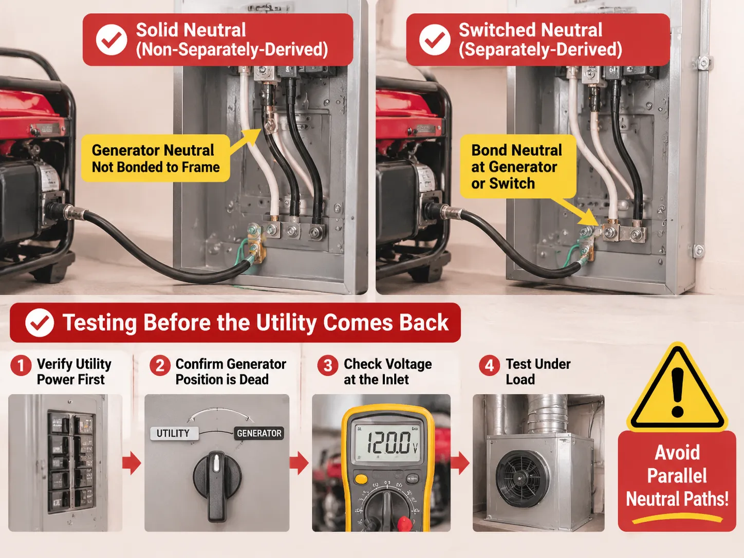
- Solid neutral, non-separately derived. The neutral of the generator and that of the utility are linked at the switch, while the generator frame remains bonded as part of the same grounding system. In this configuration, the generator’s neutral has to be unbonded from the frame, as the presence of two separate bonds in the system results in neutral current going through the ground conductors. That is the most common setup for portable generators feeding an isolation switch.
- Switched neutral, separately derived. When the switch disconnects the neutral together with hots, the generator becomes a separately derived system, and the neutral is bonded either at the generator or switch while having the grounding electrode conductor going to the grounding system of the building. This arrangement is used in much larger stationary setups and for switches rated for the service.
- The failure mode assumes the use of a portable generator with a bonded neutral in a solid neutral switch. In that case, it results in parallel neutral paths, ground current, and nuisance tripping of GFCI devices every time the generator is on. Look for the instructions that specify whether the generator neutral is bonded, examine the switch instructions for the arrangement suitable for this case, and note what you’ve found. If the two instructions contradict each other, you’ll have to do something minor yet specific to fix this issue.
Testing Before the Utility Comes Back
To ensure your safety while testing, you should start with resetting the generator by disconnecting it from the system and then checking power on the utility panel. This will show whether there is any voltage present on circuits being backed up. Following that, plug the generator in and see if there is no power in the same circuits.
After that, you will have to start the generator outside, then connect the cord and check voltage before switching on the generator. You should expect reading of 240V between the two hot phases, 120V on hot vs neutral and 120V on hot vs ground. When the neutral is missing, you will read 120V on hot vs ground and some strange voltage on hot vs neutral.
After that you have to switch to the generator and start checking the loads on circuits one by one from the highest power draw unit in each of the circuits. The best way to test the system would be to start a furnace fan. The key point here is taking the voltage when all the load is connected.
What the Job Actually Costs
The cost of the hardware for a 10-circuit manual transfer switch with an inlet and cable ranges from $500 to $900. In an installation of a manual transfer switch that has been prewired, the labor customary to be about from 2 to 4 hours, which will be costing roughly around $300 to $600. Adding the cost of the permit will bring the total to around $850 to $1,800 for the simplest of installations.
Interlock kits are relatively cheaper as compared to the previous options. The cost of interlock kits is from $50 to $150 and that of the electrician is about $150 to $400 as the task involves placing only one circuit breaker and a faceplate. You can also find expensive automatic whole house switches that may cost you $800 to $2,500 as the switch alone will take a longer period to install. For scale at the larger end, the pricing structure on a 600 A four-pole service entrance automatic transfer switch shows how quickly switchgear pricing moves once the device becomes service-rated.
Mistakes That Get Installations Redone
Double male cord. Using a cord with both ends being a male plug to connect generator to dryer outlet is the most hazardous shortcut in the industry. It backfeeds the panel and energizes service conductors, which may kill utility personnel or damage the generator when the grid goes back online. In addition to this, it is against code everywhere, and no inspector will let it go.
Undersized conductors. A 50 A switch fed using 10 AWG wire simply because it happens to be available on the truck. Even though the breaker does its job, the wire overheats, and the failure can take place months later.
Generator placed too close to the house. The total number of fatalities due to carbon monoxide poisoning in America reaches about 100 each year, and nearly 80% of those happen in domestic settings. So, the generator must be kept outside, at a considerable distance from the doors and windows, exhaust pointing away from the house and a battery-powered CO alarm operating on all floors.
No load calculation. When the generator is connected to a switch with many circuits that cannot be supported by the generator, the breaker will trip at the first cold night. So, the watts for all devices must be calculated to avoid any problem.
Unmarked circuits. A panel directory made with a pencil and never updated can create a problem during the blackout that happens in the middle of the night. It is recommended to print the panel directory so there is a copy available when needed.
Manual or Automatic: Which One Belongs in Your House
Manual switches are based on the premise that the individual is in the house, awake, and able to venture out into inclement weather. This is acceptable for most homes and outages, which last hours rather than days. However, manual switches fail houses with wet basements containing a sump pump, people with medical conditions, or an owner on the move.
On the other hand, automatic switches operate on the understanding that a generator is permanently installed and supplied with a start signal, has been provided with enough fuel to run for several days, and has a functioning exercise regimen. The 100 A automatic transfer switch is the size band that suits a service-rated residential installation, with adjustable transfer and retransfer delays so the generator is not asked to accept load before it is ready.The trade is legit: an ATS costs about 2 to 4 times more than a manual switch plus required equipment like a battery, controller and yearly service costs. In exchange you get lights without needing to leave bed.
A practical way could help reduce costs. You could set a large manual switch and leave space in the box for a controller later on. Panel and input costs are usually high, and it is easy to change a mechanism later.
FAQ
Can I install a generator transfer switch myself?
In various localities it is possible for a resident to apply for an electrical permit for installation on their personal single-family house and perform the necessary work pending inspection. It is the conditions that are important rather than the permission: the panel should be turned off, the wires should be of adequate size, the neutral connection should correspond to the one on the generator, and the installation should be performed properly. If anything in those four requirements is questionable, then the answer should be ‘no’. Interlocking kits are the easiest choice for DIY enthusiasts, but still need to be certified and compatible with the given model of the electrical panel.
How much does it cost to put in a generator transfer switch?
If you’re purchasing a hard-wired 10-circuit manual switch, your hardware expenses will generally fall in the range of $400 to $800, while installation by an electrician will run between $300 and $600. Permits will often cost from $50 to $300, for a total installed cost of between approximately $850 and $1,800. Interlock kits run from $50 to $150 in parts and from $150 to $400 for installation. A whole-house automatic switching mechanism for the use of a standby generator runs from $800 to $2,500, with the actual cost of installing such a switch higher, since service conductors and wiring for the control of the generator are necessary. An inlet box and a long enough cord often add about $100 to $300 to the installation estimate, but are sometimes left out.
Can a homeowner install a generator transfer switch?
Often, the permit is the determining aspect, and not really the talent. Some municipal building departments allow owner-permit electrical work on an owner-occupied single-family dwelling and with the inspection; a very few require a licensed electrician to do anything that is considered to take place inside of the service panel. Be sure to call the authority having jurisdiction before you buy anything hardware-wise, since that is going to change the picture entirely. Note as well that the unpermitted installation could be enough for the insurer to deny a fire claim which is in fact much larger than the amount you saved on labour.
What size transfer switch do I need for a 10,000 watt generator?
The switch is rated for 50 A. The calculation of operating wattage divided by 240 V yields the result of 10,000 ÷ 240, which is 41.7 A. The next standard size switch is, therefore, 50 A. Only operating wattage should be considered and not starting wattage since a switch operates continuously on the same current. A 50 A switch requires six AWG wires made of copper material and a double pole 50 A breaker on the utility side. If the generator outlet is 30 A L14-30 versus 50 A 14-50 then both switch and inlet have to match the outlet and the generator will be limited by the socket.
Do I need a transfer switch if I only use extension cords?
No, and that is the only legally permissible option. Instead of wiring the generator into your house system, extension cords are used to connect the generator with an appliance, thus making the generator independent of the house wiring which prevents any backfeed. This means convenience and safety: runners through the doors, no fixed electrical loads such as contacting pumps or a furnace, and clogged path with obstacles in the dark. The minute you need to use electricity in a fixed installation, you must use a transfer device according to NECA702.
Références
- Electrical Engineering Portal — Installing a Manual Transfer Switch
- NFPA — National Electrical Code, Article 702 Optional Standby Systems
- Generac — Home Standby and Transfer Switch Products
- Reliance Controls — Manual Transfer Switch and Inlet Box Systems
- ASCO Power Technologies — Automatic Transfer Switch Engineering
Conclusion
Installing the generator system is easy. The tough part is deciding. Size from running watts, keep switched and inlet matched to generator output and establish the neutral before pulling the first wire because that’s what fails inspection and puts current where it should not go.
Then buy hardware only once. A switch rated one size above your generator will cost only a bit more and will never let you down; a switch that is rated one size below will ruin the generator you already have. If you tell us what your generator’s continuous rating is, its outlet and whether or not its neutral is bonded we will tell you which board and which pole configuration you need for the job.