
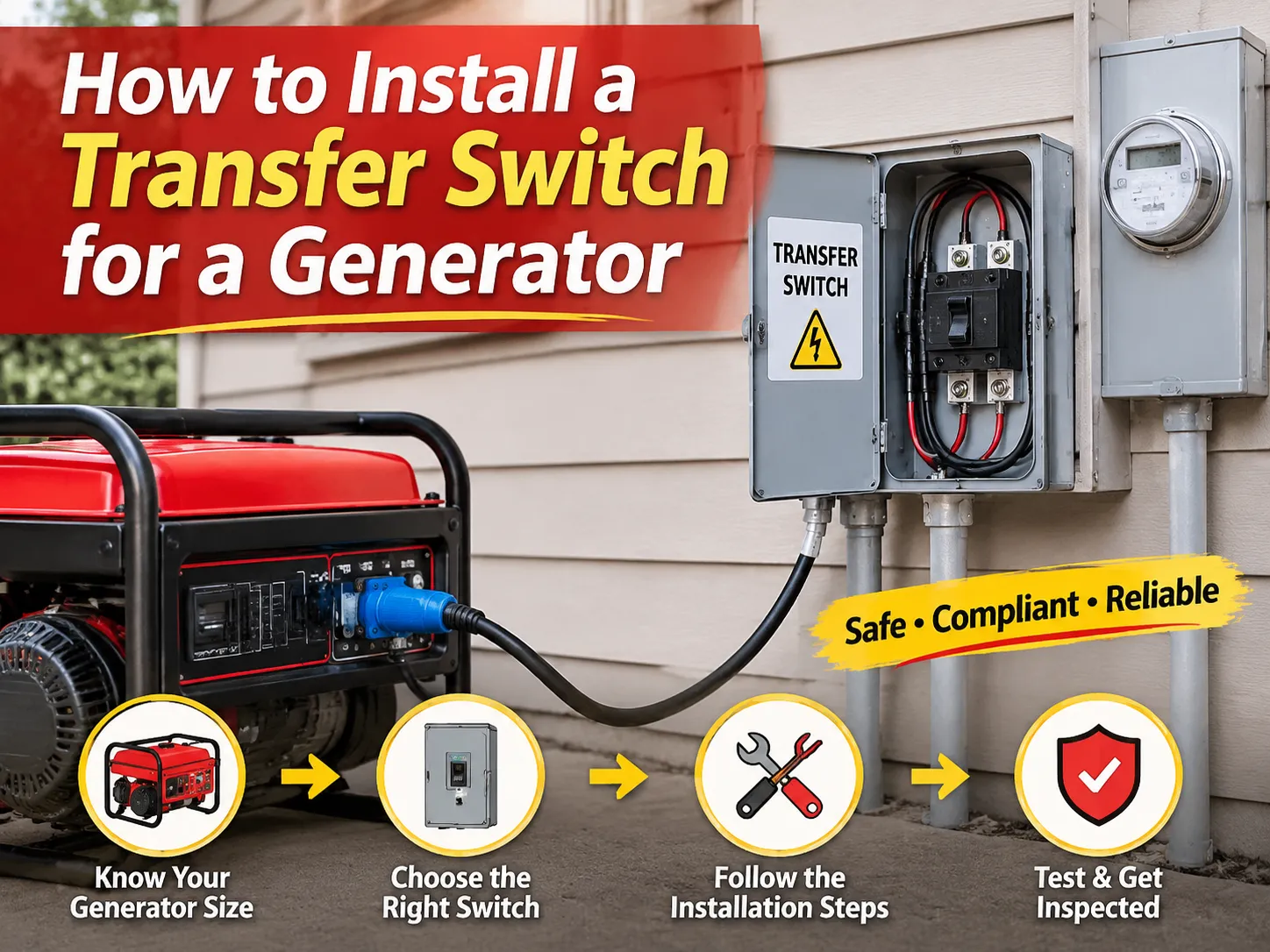
Cada inverno, há alguém em uma casa sem aquecimento que olha para o painel, lança um olhar para o gerador na garagem e se pergunta se é suficiente se ele conseguir um cabo e duas garras jacaré. Não é suficiente, e a justificativa para isso não é a papelada. A razão é que o retorno de alimentação para o painel coloca a tensão do gerador no lado do usuário da instalação, tornando possível que um técnico da rede que chega para restaurar a rede a encontre. É por isso que existe um interruptor de transferência, e por que a instalação gira em torno de uma questão básica: como garantir que o lado do usuário do gerador e da rede nunca possam ser conectados fisicamente, e como estabelecer isso.
O conjunto de requisitos apresentado abaixo baseia-se na suposição de que o circuito em questão é um circuito monofásico que opera na América do Norte e que utiliza um gerador portátil ou de reserva. A sequência é bastante deliberada; o processo de dimensionamento é o primeiro passo, pois impacta todas as outras ações realizadas posteriormente no processo, depois passando para o trabalho mecânico, e então para condutores, neutro e aterramento, que inesperadamente se mostram decisões importantes que um número surpreendente de pessoas deixa para o inspetor resolver.
Um interruptor de transferência deve ter uma classificação igual ou superior à saída do seu gerador e deve conter a fiação do tamanho correto para essa classificação, além de ser instalado de forma que a corrente da rede elétrica e as correntes da capacidade do gerador não se combinem em um ponto. Por exemplo, o gerador portátil de 10.000 W produzirá uma saída de aproximadamente 41,7 A em 240 V, portanto, é aconselhável comprar um interruptor de 50 A e fiação de cobre 6 AWG. Os custos para hardware no caso de interruptores manuais pré-fiação variam entre $400 e $800, enquanto um kit de intertravamento licenciado pode custar entre $50 e $150. Custos adicionais incluirão o trabalho dos eletricistas, estimado entre $300 e $600, e permissões. A instalação pode ser dividida em quatro operações mecânicas e três elétricas: seleção de circuitos, instalação do interruptor, instalação da caixa de entrada e passagem dos cabos, alimentação da rede e aterramento do gerador após a realização do teste. A seção sobre neutro deve ser lida primeiro, pois representa o ponto onde as considerações relacionadas a este trabalho mais falham.
Qual Interruptor de Transferência Você Realmente Precisa
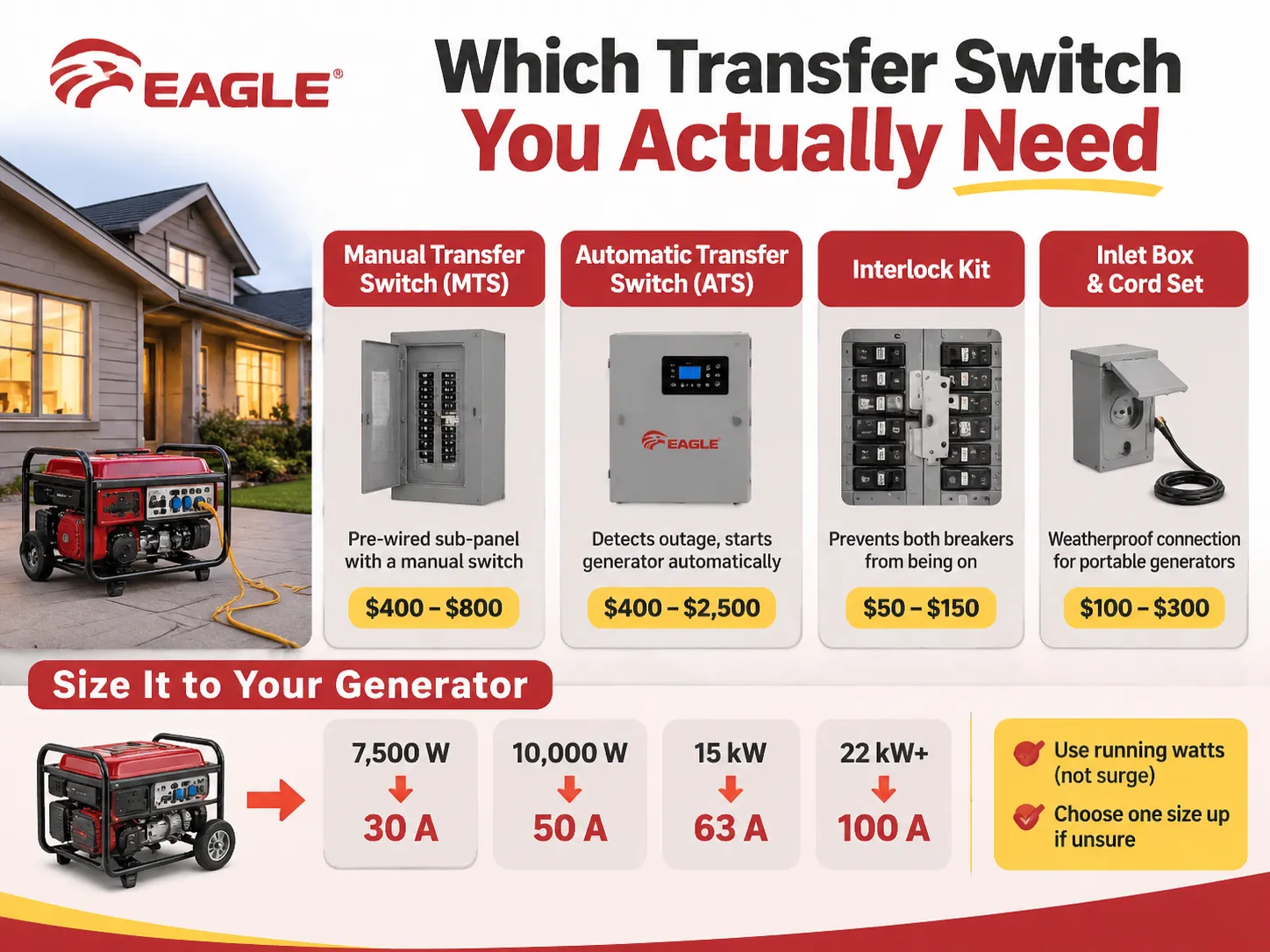
Quatro tipos de dispositivos são identificados como interruptores de transferência, e eles não podem ser usados em substituição uns aos outros. Sua escolha aqui dependerá se você tem um gerador portátil ou fixo, se alguém estará em casa no momento da queda de energia, e o tamanho da casa que precisa ser alimentada.
| Produto | Custo do hardware | O que ele faz | Compatível |
|---|---|---|---|
| Interruptor de transferência manual (MTS) | $400 a $800 | Subpainel pré-fiação com 6 a 16 circuitos ramificados e um mecanismo de duas posições que você aciona manualmente | Geradores portáteis, proprietários presentes durante as quedas de energia |
| Chave de transferência automática (ATS) | $400 a $2.500 | Detecta perda da rede, inicia o gerador, transfere a carga, retransfere e resfria na restauração | Geradores de reserva com controlador de partida de dois fios |
| Kit de intertravamento | $50 a $150 | Uma placa deslizante listada que impede que o disjuntor principal e o do gerador estejam ligados simultaneamente | Painéis modernos com dois espaços adjacentes livres, cobertura para toda a casa |
| Caixa de entrada e conjunto de cabo | $100 a $300 | O ponto de conexão à prova de intempéries na parede externa, além do cabo para o gerador | Toda instalação portátil, junto com uma das opções acima |
Em contraste com um dispositivo elétrico, um interruptor deve ser um subpainel, e essa distinção deve ser feita no balcão. Ele virá com seus próprios disjuntores, um conjunto de cabos instalados de fábrica, e o instalador transferirá os circuitos ramais adequados do painel principal para ele. Linha de interruptores manuais classe PC mostra a construção: duas posições de interrupção intertravadas, um invólucro comum e capacidade de terminais para as alimentações da concessionária e do gerador. Um kit de intertravamento serve à função oposta. Ele não adiciona nada à contagem de circuitos – apenas torna o painel seguro, razão pela qual funciona tão bem em uma casa onde o gerador é grande o suficiente para alimentar tudo.
Dimensionando o Interruptor para o Gerador, Não para o Painel
A classificação de amperagem é determinada dividindo a potência contínua do gerador por 240 volts. Uma máquina de 10 kW gera 41,7 A, o que corresponde a um interruptor de 50 A. Um gerador de 7,5 kW gera 31,3 A para um interruptor de 30 A, enquanto um gerador de 12 kW gera exatamente 50 A, tornando-se o limite superior das unidades móveis populares.
Ao calcular a amperagem, use estas duas regras: utilize watts em funcionamento e nunca watts de surto, pois o interruptor é classificado para carga contínua. Nunca subestime o interruptor, pois um interruptor de 30 A em um gerador de 50 A apenas limitará a saída do gerador, tornando desnecessário o trabalho de adivinhação sobre a operação do gerador. Escolher um interruptor com classificação maior não causará danos; no entanto, escolher um com classificação inferior será contrário ao bom senso.
Acima da faixa portátil, a aritmética muda de forma. Uma unidade de 15 kW necessita de um dispositivo de 63 A a 240 V, que é a faixa de tamanho onde o interruptor de transferência automática de 63 A se encontra, e um gerador de reserva para toda a casa de 22 kW passa para um interruptor classificado para serviço de 100 A. A partir desse ponto, o interruptor é classificado para o serviço, não para a máquina, pois está sendo inserido entre o medidor e o painel principal.
Ferramentas e Materiais Antes de Começar
Os instrumentos são normais com uma exceção. A chave de torque é necessária. O valor do torque é indicado nos terminais dos disjuntores e interruptores de transferência, e geralmente um terminal solto causa a falha após algum tempo.
Chaves de fenda isoladas, encaixe quadrado, decapadores de fios classificados para 6 AWG, chave de torque em polegadas-libra, testador de voltagem bipolar (lembre-se que a chave de fenda neon não é o testador), caneta de voltagem sem contato, fita guia, furadeira com serras para penetrar a parede e um telefone para tirar fotos antes e depois do trabalho também devem estar no seu conjunto de ferramentas. As fotos não podem ser consideradas simplesmente como fotos. Elas são a prova do aterramento e ligação corretos quando a cobertura é instalada.
Materiais: interruptor, caixa de entrada classificada como NEMA 3R caso esteja sendo instalada externamente, quatro fios da bitola regulamentada, conduíte e acessórios, disjuntor bipolar para o fornecimento de energia, selante para intempéries, etiquetas, cabo de gerador de comprimento suficiente. Os kits geralmente vêm com um cabo de 10 pés, que acaba sendo muito curto considerando o fato de que o gerador é instalado longe da casa e o escapamento fica do lado oposto.
Passo 1 a Passo 4: Permissão, Isolamento, Circuitos e Montagem
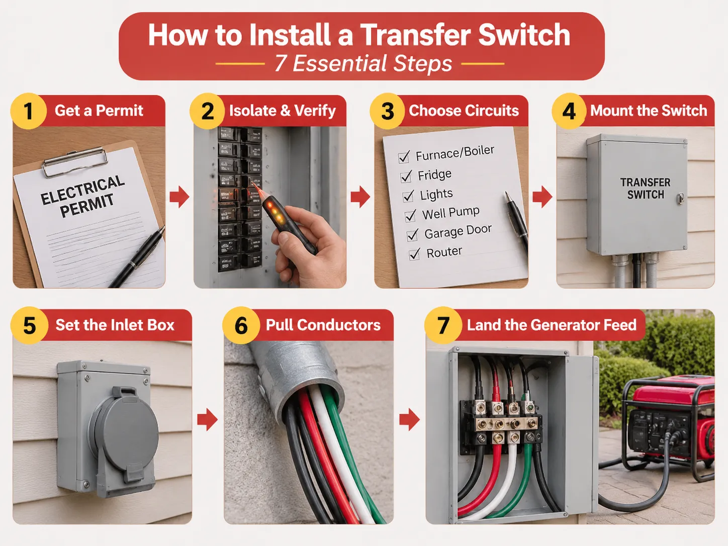
- Passo 1. Obtenha uma aprovação antecipadamente. Quase todos os municípios exigem que você obtenha uma permissão elétrica juntamente com uma inspeção do interruptor de transferência, que geralmente custa entre $50 e $300. É mais econômico obter sua permissão primeiro do que após a conclusão de todo o trabalho. Em algumas jurisdições, as inspeções não podem ser agendadas retroativamente.
- Passo 2. Desconecte e verifique. Desligue primeiro seu disjuntor principal. Depois disso, use um testador bipolar para verificar os terminais. Testar no painel enquanto seu disjuntor principal está desligado indica o status de funcionamento do seu disjuntor principal, mas não significa que seus terminais estejam seguros se algo acontecer com seu disjuntor principal ou houver outra fonte de energia.
- Passo 3. Selecione os circuitos. Ao usar um interruptor manual, você pode conectar cerca de 5 a 16 circuitos. Você deve fazer uma lista precisa que inclua apenas os dispositivos que precisam ser conectados durante o funcionamento. Conte duas cargas se forem 240 volts. Não caia na armadilha de incluir seu fogão e secadora, pois é impossível para geradores portáteis operar esses dispositivos.
- Passo 4. Instale o interruptor. Você precisa posicioná-lo perto do painel principal para que as corridas do conduíte sejam curtas. Falta de espaço sob o invólucro ou comprimento errado do fio é um problema de código que precisa de resolução adicional. Você também deve montar o interruptor nivelado.
Passo 5 a Passo 7: Conduíte, Condutores e a Caixa de Entrada
- Passo 5. Fixe a caixa de entrada na posição. A caixa deve idealmente ser colocada em uma parede externa, não muito longe de onde o gerador será instalado. A altura também deve ser escolhida para que não haja neve ou água parada no cabo. A entrada NEMA 14-50R fornece dois fios quentes, um neutro e uma conexão de aterramento. O outro tipo comum de entrada é o CS6375, a escolha dependerá do plugue do gerador. Escolher o errado fará com que você tenha que comprar outra entrada ou um adaptador. Em qualquer caso, adaptadores de 50A não são favoráveis em ambientes úmidos.
- Passo 6. Puxe os condutores. Para o sistema de 50 A, são necessários quatro condutores de cobre 6 AWG: um preto, um vermelho, um branco e um verde. Condutores de cobre 6 AWG podem transportar com segurança 65 A a uma temperatura de 75 °C. Portanto, pode-se dizer que a queda de tensão em um condutor para um percurso de 50 pés é aproximadamente 2%, dentro dos 3% permitidos de queda de tensão no alimentador. Cabo NM-B não pode ser usado dentro de um conduíte externo ou em área úmida, portanto, deve-se usar THHN ou XHHW em um eletroduto. O tamanho do conduíte deve ser apropriado ao número de condutores utilizados, permitindo uma fácil instalação.
- Step 7. Land the generator feed from the generator to the hot bar. The generator feed making the hot, neutral and ground connections. Once these connections have been made, conduct the utilities connection from the two-pole breaker in the main panel. The two connections should be kept separated in the enclosure. The conductors should be dressed to avoid crossing of moving contacts.
Wiring the Switch: Utility Side, Generator Side, and the Breaker That Feeds It
The utility side comes from a new two-pole breaker in the main panel, sized to the switch rating. For a 50 A switch that is a 50 A two-pole breaker, and a standard thermal-magnetic device of the kind in this 63 A miniature circuit breaker range is what the circuit expects: 6 kA or 10 kA interrupting capacity, C curve for mixed loads, and a torque value that has to be honoured on both lugs.
The generator-side voltage-derived comes into the inlet box. Within a manual switch, there are two breaker positions for each branch circuit: one fed from the utility bus and the other, in turn, fed from the generator bus. And the mechanism ensures that only one bus is energized at any time. This is the whole trick, and it is mechanical-as opposed to electronic-in nature. There’s no way to bypass it with a software bug or a stuck relay.
Within an automatic switch, the logic is contrary. A controller would monitor both sources, start the generator, wait for the frequencies and voltages to stabilize, and then activate the motor-operated mechanism. This transfer is temporarily delayed for two reasons: first, an accelerating generator produces low voltage at low frequency, and closing onto a load at this time causes failure of compressor motors; second, a changeover is put on hold for a second reason, which lies in order that the utility can settle down before handing back the house.
The Neutral Question That Fails More Inspections Than Anything Else
There are two valid ways to manage the neutral, and making the incorrect choice will lead to either shock risks or nuisance trips.
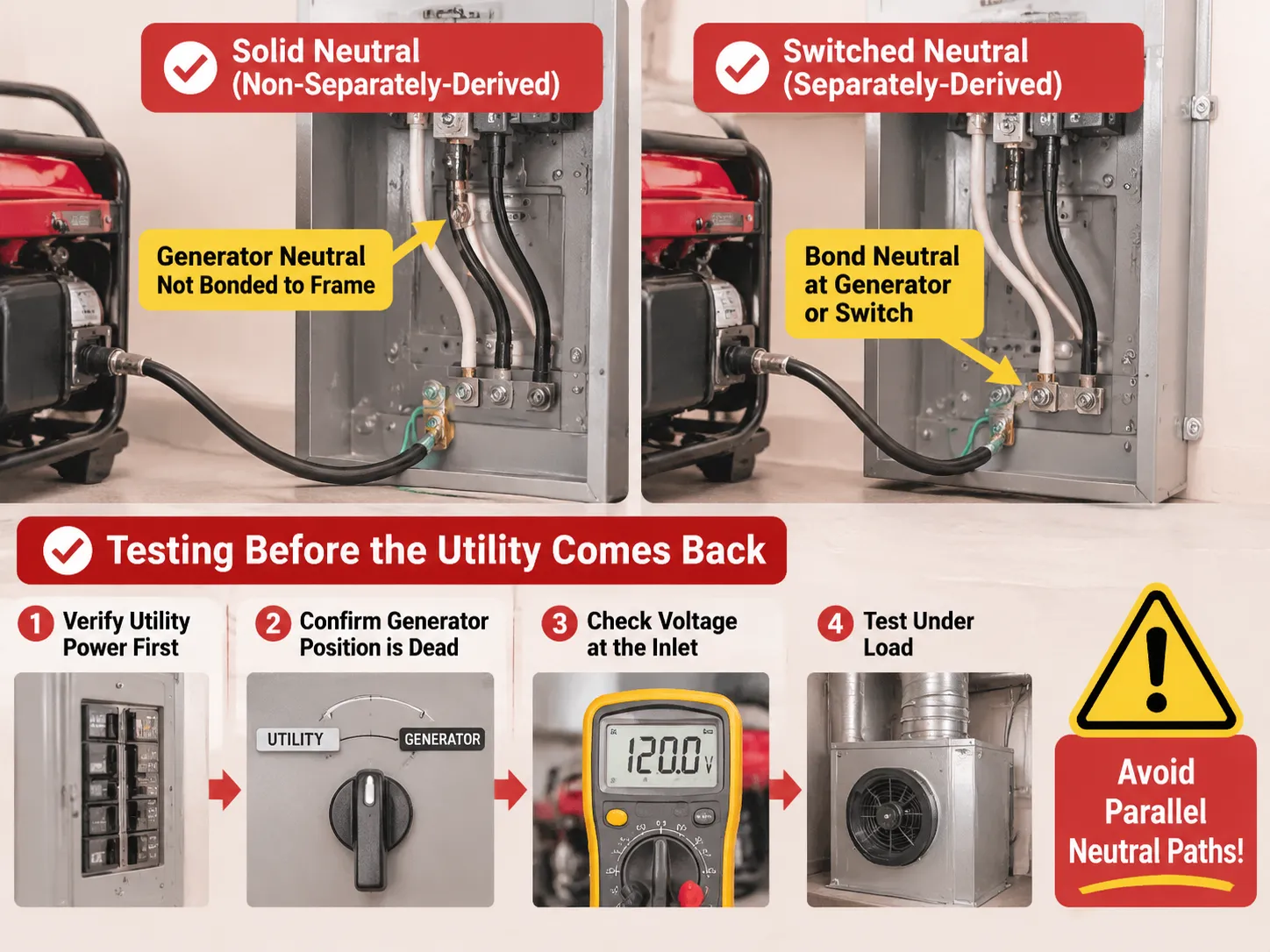
- Solid neutral, non-separately derived. The neutral of the generator and that of the utility are linked at the switch, while the generator frame remains bonded as part of the same grounding system. In this configuration, the generator’s neutral has to be unbonded from the frame, as the presence of two separate bonds in the system results in neutral current going through the ground conductors. That is the most common setup for portable generators feeding an isolation switch.
- Switched neutral, separately derived. When the switch disconnects the neutral together with hots, the generator becomes a separately derived system, and the neutral is bonded either at the generator or switch while having the grounding electrode conductor going to the grounding system of the building. This arrangement is used in much larger stationary setups and for switches rated for the service.
- The failure mode assumes the use of a portable generator with a bonded neutral in a solid neutral switch. In that case, it results in parallel neutral paths, ground current, and nuisance tripping of GFCI devices every time the generator is on. Look for the instructions that specify whether the generator neutral is bonded, examine the switch instructions for the arrangement suitable for this case, and note what you’ve found. If the two instructions contradict each other, you’ll have to do something minor yet specific to fix this issue.
Testing Before the Utility Comes Back
To ensure your safety while testing, you should start with resetting the generator by disconnecting it from the system and then checking power on the utility panel. This will show whether there is any voltage present on circuits being backed up. Following that, plug the generator in and see if there is no power in the same circuits.
After that, you will have to start the generator outside, then connect the cord and check voltage before switching on the generator. You should expect reading of 240V between the two hot phases, 120V on hot vs neutral and 120V on hot vs ground. When the neutral is missing, you will read 120V on hot vs ground and some strange voltage on hot vs neutral.
After that you have to switch to the generator and start checking the loads on circuits one by one from the highest power draw unit in each of the circuits. The best way to test the system would be to start a furnace fan. The key point here is taking the voltage when all the load is connected.
What the Job Actually Costs
The cost of the hardware for a 10-circuit manual transfer switch with an inlet and cable ranges from $500 to $900. In an installation of a manual transfer switch that has been prewired, the labor customary to be about from 2 to 4 hours, which will be costing roughly around $300 to $600. Adding the cost of the permit will bring the total to around $850 to $1,800 for the simplest of installations.
Interlock kits are relatively cheaper as compared to the previous options. The cost of interlock kits is from $50 to $150 and that of the electrician is about $150 to $400 as the task involves placing only one circuit breaker and a faceplate. You can also find expensive automatic whole house switches that may cost you $800 to $2,500 as the switch alone will take a longer period to install. For scale at the larger end, the pricing structure on a 600 A four-pole service entrance automatic transfer switch shows how quickly switchgear pricing moves once the device becomes service-rated.
Mistakes That Get Installations Redone
Double male cord. Using a cord with both ends being a male plug to connect generator to dryer outlet is the most hazardous shortcut in the industry. It backfeeds the panel and energizes service conductors, which may kill utility personnel or damage the generator when the grid goes back online. In addition to this, it is against code everywhere, and no inspector will let it go.
Undersized conductors. A 50 A switch fed using 10 AWG wire simply because it happens to be available on the truck. Even though the breaker does its job, the wire overheats, and the failure can take place months later.
Generator placed too close to the house. The total number of fatalities due to carbon monoxide poisoning in America reaches about 100 each year, and nearly 80% of those happen in domestic settings. So, the generator must be kept outside, at a considerable distance from the doors and windows, exhaust pointing away from the house and a battery-powered CO alarm operating on all floors.
No load calculation. When the generator is connected to a switch with many circuits that cannot be supported by the generator, the breaker will trip at the first cold night. So, the watts for all devices must be calculated to avoid any problem.
Unmarked circuits. A panel directory made with a pencil and never updated can create a problem during the blackout that happens in the middle of the night. It is recommended to print the panel directory so there is a copy available when needed.
Manual or Automatic: Which One Belongs in Your House
Manual switches are based on the premise that the individual is in the house, awake, and able to venture out into inclement weather. This is acceptable for most homes and outages, which last hours rather than days. However, manual switches fail houses with wet basements containing a sump pump, people with medical conditions, or an owner on the move.
On the other hand, automatic switches operate on the understanding that a generator is permanently installed and supplied with a start signal, has been provided with enough fuel to run for several days, and has a functioning exercise regimen. The 100 A automatic transfer switch is the size band that suits a service-rated residential installation, with adjustable transfer and retransfer delays so the generator is not asked to accept load before it is ready.The trade is legit: an ATS costs about 2 to 4 times more than a manual switch plus required equipment like a battery, controller and yearly service costs. In exchange you get lights without needing to leave bed.
A practical way could help reduce costs. You could set a large manual switch and leave space in the box for a controller later on. Panel and input costs are usually high, and it is easy to change a mechanism later.
FAQ
Can I install a generator transfer switch myself?
In various localities it is possible for a resident to apply for an electrical permit for installation on their personal single-family house and perform the necessary work pending inspection. It is the conditions that are important rather than the permission: the panel should be turned off, the wires should be of adequate size, the neutral connection should correspond to the one on the generator, and the installation should be performed properly. If anything in those four requirements is questionable, then the answer should be ‘no’. Interlocking kits are the easiest choice for DIY enthusiasts, but still need to be certified and compatible with the given model of the electrical panel.
How much does it cost to put in a generator transfer switch?
If you’re purchasing a hard-wired 10-circuit manual switch, your hardware expenses will generally fall in the range of $400 to $800, while installation by an electrician will run between $300 and $600. Permits will often cost from $50 to $300, for a total installed cost of between approximately $850 and $1,800. Interlock kits run from $50 to $150 in parts and from $150 to $400 for installation. A whole-house automatic switching mechanism for the use of a standby generator runs from $800 to $2,500, with the actual cost of installing such a switch higher, since service conductors and wiring for the control of the generator are necessary. An inlet box and a long enough cord often add about $100 to $300 to the installation estimate, but are sometimes left out.
Can a homeowner install a generator transfer switch?
Often, the permit is the determining aspect, and not really the talent. Some municipal building departments allow owner-permit electrical work on an owner-occupied single-family dwelling and with the inspection; a very few require a licensed electrician to do anything that is considered to take place inside of the service panel. Be sure to call the authority having jurisdiction before you buy anything hardware-wise, since that is going to change the picture entirely. Note as well that the unpermitted installation could be enough for the insurer to deny a fire claim which is in fact much larger than the amount you saved on labour.
What size transfer switch do I need for a 10,000 watt generator?
The switch is rated for 50 A. The calculation of operating wattage divided by 240 V yields the result of 10,000 ÷ 240, which is 41.7 A. The next standard size switch is, therefore, 50 A. Only operating wattage should be considered and not starting wattage since a switch operates continuously on the same current. A 50 A switch requires six AWG wires made of copper material and a double pole 50 A breaker on the utility side. If the generator outlet is 30 A L14-30 versus 50 A 14-50 then both switch and inlet have to match the outlet and the generator will be limited by the socket.
Do I need a transfer switch if I only use extension cords?
No, and that is the only legally permissible option. Instead of wiring the generator into your house system, extension cords are used to connect the generator with an appliance, thus making the generator independent of the house wiring which prevents any backfeed. This means convenience and safety: runners through the doors, no fixed electrical loads such as contacting pumps or a furnace, and clogged path with obstacles in the dark. The minute you need to use electricity in a fixed installation, you must use a transfer device according to NECA702.
Referências
- Electrical Engineering Portal — Installing a Manual Transfer Switch
- NFPA — National Electrical Code, Article 702 Optional Standby Systems
- Generac — Home Standby and Transfer Switch Products
- Reliance Controls — Manual Transfer Switch and Inlet Box Systems
- ASCO Power Technologies — Automatic Transfer Switch Engineering
Conclusão
Installing the generator system is easy. The tough part is deciding. Size from running watts, keep switched and inlet matched to generator output and establish the neutral before pulling the first wire because that’s what fails inspection and puts current where it should not go.
Then buy hardware only once. A switch rated one size above your generator will cost only a bit more and will never let you down; a switch that is rated one size below will ruin the generator you already have. If you tell us what your generator’s continuous rating is, its outlet and whether or not its neutral is bonded we will tell you which board and which pole configuration you need for the job.