Jika Anda baru saja membeli unit pendingin udara baru, charger kendaraan listrik, atau oven komersial, teknisi Anda mungkin akan menanyakan minimum circuit ampacity yang tersedia dari nameplate. Pada saat itu, Anda mungkin akan melihat angka yang tampak tidak berarti bagi Anda. Jika Anda melakukan kesalahan, Anda bisa saja menggunakan kabel yang ukurannya terlalu kecil (dan dengan demikian – dapat mengalami pemanasan berlebih, menyebabkan trip gangguan, dan mungkin kebakaran), atau Anda bisa menghabiskan terlalu banyak uang untuk mengkabelnya dengan kabel yang terlalu besar.
Dalam panduan ini, Anda akan mempelajari apa arti minimum circuit ampacity, bagaimana cara menghitungnya, apa perbedaan antara minimum circuit ampacity dan ukuran pemutus sirkuit, serta bagaimana mengubah minimum circuit ampacity ini menjadi ukuran kabel yang tepat — sesuai dengan peraturan NEC dalam prosesnya.
Dalam kata sederhana, MCA atau Minimum Circuit Ampacity adalah kapasitas minimum kabel yang diperlukan untuk menjalankan perangkat dengan benar. Untuk menghitungnya, gunakan aturan NEC 125%, yang mengharuskan mengalikan beban kontinu terbesar, yaitu arus penuh motor terbesar, dengan 1,25, bersama dengan semua beban lainnya. Setelah itu, kabel terkecil yang memenuhi atau melebihi persyaratan ini sesuai dengan Tabel NEC 310.16 harus dipilih.
Apa Itu Minimum Circuit Ampacity?
Minimum Circuit Ampacity adalah nilai terkecil yang dihitung dan dinyatakan dalam ampere yang menunjukkan ampacity minimum dari konduktor sirkuit yang diperlukan untuk memasok beban tanpa mengalami pemanasan berlebih. MCA tidak menunjukkan jumlah arus yang sebenarnya akan dikonsumsi peralatan dalam penggunaan normal. Sebaliknya, ini adalah persyaratan minimum yang diambil dari kode untuk memastikan ada margin keamanan untuk operasi kontinu sirkuit dan untuk arus lonjakan saat start.
Dalam praktiknya, Anda akan menemukan MCA pada nameplate sistem HVAC, pompa panas, unit pendingin komersial, pemanas air, charger kendaraan listrik, dan sebagian besar perangkat yang melibatkan motor dan elemen pemanas. Produsen harus mencantumkannya untuk mematuhi kode yang menyatakan bahwa wajib memperhitungkan ukuran kabel yang tepat dengan margin yang memadai. Selain itu, hanya produsen yang mengetahui kombinasi terburuk dari bagaimana beban beroperasi.
Poin terpenting adalah Anda harus mematuhi MCA yang diperlukan dari konduktor. Misalnya, jika nameplate menunjukkan nilai MCA sebesar 26,4 A, maka kabel harus memiliki rating tidak kurang dari level ini (yaitu, mematuhi level ini setelah disesuaikan dengan faktor derating).
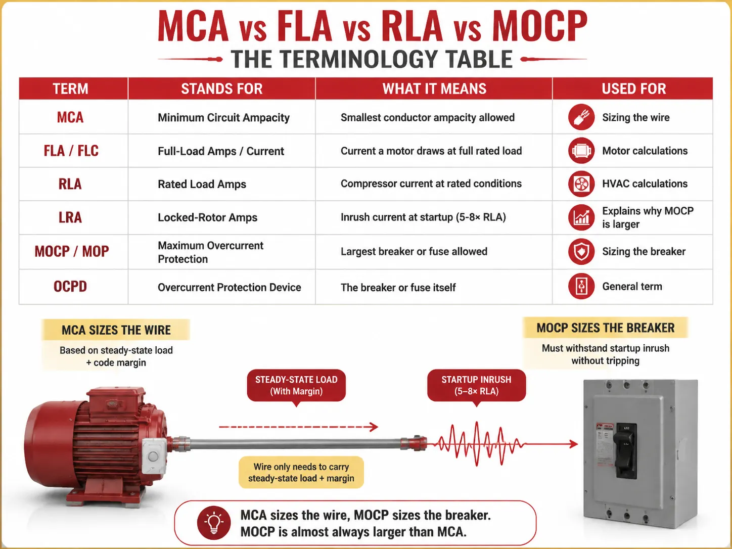
MCA vs FLA vs RLA vs MOCP: Tabel Terminologi
Setengah dari kebingungan seputar MCA berasal dari singkatan di sebelahnya pada nameplate. Berikut adalah arti sebenarnya dari setiap istilah:
| Istilah | Singkatan Untuk | Apa Artinya | Digunakan Untuk |
|---|---|---|---|
| MCA | Ampasitas Sirkuit Minimum | Ampacity konduktor terkecil yang diizinkan | Menentukan ukuran kabel |
| FLA / FLC | Arus Beban Penuh / Arus | Arus yang ditarik motor pada beban penuh terukur | Perhitungan motor |
| RLA | Arus Beban Terukur | Arus kompresor pada kondisi terukur | Perhitungan HVAC |
| LRA | Arus Rotor Terkunci | Arus inrush saat startup (5-8× RLA) | Menjelaskan mengapa MOCP lebih besar |
| MOCP / MOP | Perlindungan Overcurrent Maksimum | Pemutus sirkuit atau sekering terbesar yang diizinkan | Menentukan ukuran pemutus sirkuit |
| OCPD | Perangkat Perlindungan Overcurrent | Pemutus sirkuit atau sekering itu sendiri | Istilah umum |
Komponen utama dari pemodelan mental adalah mempertimbangkan dua parameter berbeda yang terlibat dalam perhitungan ini — MCA dan MOCP, yang bukan angka yang sama — yang pertama biasanya lebih kecil dari yang kedua karena pemutus sirkuit harus menahan lonjakan arus saat peralatan dinyalakan sementara kabel menangani aliran arus yang berkelanjutan plus faktor-faktor yang ditetapkan oleh kode.
Penjelasan Aturan 125%
Aturan 125% merupakan dasar dari setiap perhitungan MCA. Aturan ini dapat ditemukan di berbagai bagian NEC dan, di setiap bagian tersebut, tujuannya adalah memberikan margin keselamatan tertentu dalam kasus beban yang bekerja secara terus-menerus atau beban yang dinyalakan dengan arus inrush.
- NEC 210.19(A)(1) — sirkuit cabang: kabel harus memiliki ampacity minimum 125% dari beban kontinu, dan 100% dari beban non-kontinu. Beban disebut sebagai “beban kontinu” jika beban tersebut beroperasi pada nilai penuh selama 3 jam atau lebih (definisi NEC 100).
- NEC 215.2 — feeder: persyaratan 125% yang sama juga berlaku untuk feeder.
- NEC 430.22 — satu motor: kabel harus dihitung berdasarkan 125% dari FLA motor.
- NEC 440.22 / praktik pabrikan — HVAC: MCA = 125% dari RLA untuk motor terbesar.
Mengapa 125%? Ada dua alasan untuk ini. Pertama, tidak ada panas kontinu: ketika kabel membawa arus terukurannya dalam waktu lama, kabel akan memanas hingga suhu puncaknya. Tambahan 25% berarti isolasi tetap dingin. Kedua, saat memulai, motor yang beroperasi dalam mode reguler menarik arus jauh lebih besar daripada saat operasi motor sebenarnya.
Cara Menghitung MCA (Dengan Contoh yang Dikerjakan)
Untuk motor individual (mengikuti kode NEC 430.22),
MCA = FLA motor × 1.25
Sebagai contoh, jika ada motor 3 HP, 230V fase tunggal dengan FLA 17 A maka,
MCA = 17 × 1.25 = 21.25 A. Sekarang, menurut tabel NEC 310.16 (kolom 75 °C), dapat disimpulkan bahwa kabel kecil yang dapat menangani nilai 21.25 A ini adalah 12 AWG, yang memiliki rating kemampuan membawa arus sebesar 25 A.
Untuk sistem beban ganda (NEC 430.24),
MCA = (FLA motor tertinggi × 1,25) + semua SLA motor lainnya
| Beban | FLA (Ampere) | Pengali | Kontribusi |
|---|---|---|---|
| Motor terbesar (10 HP, 460V) | 14.0 | ×1.25 | 17,5 A |
| Motor kedua (5 HP) | 7.6 | ×1.00 | 7,6 A |
| Motor ketiga (2 HP) | 3.4 | ×1.00 | 3,4 A |
| Total MCA | 28,5 A | ||
Untuk 28,5A, NEC 310.16 (75°C) menyatakan kawat tembaga 10 AWG (35A) adalah ukuran terkecil yang memadai — 12 AWG (25A) akan terlalu kecil.
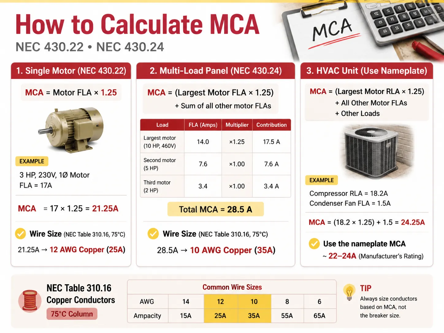
Dalam kasus unit HVAC dengan kompresor dan motor kipas, nilai RLA ideal adalah sebagai berikut: MCA = (RLA Motor Terbesar × 1,25) + FLA Motor Lain + Beban Lain.
Misalnya, jika kompresor memiliki RLA 18,2 Ampere dan kipas kondensor memiliki FLA 1,5 Ampere, maka kita memiliki: MCA = (18,2 × 1,25) + 1,5 = 24,25 Ampere.
Harap diingat bahwa nilai ini dibulatkan oleh pabrikan menjadi standar yang lebih umum 22-24 Ampere, pada nameplate unit HVAC.
MCA vs Perlindungan Overcurrent Maksimum (MOCP)
Di sinilah sering terjadi kesalahan oleh para DIYer: mereka mengira pemutus sirkuit harus sesuai dengan MCA. Tidak demikian. Pemutus sirkuit dinilai menurut MOCP, yang berbeda dari angka pada nameplate.
| Faktor | MCA (Kawat) | MOCP (Pemutus Sirkuit) |
|---|---|---|
| Apa yang diukur | Konduktor (kawat) | Perangkat overcurrent (pemutus sirkuit/sekring) |
| Hubungan tipikal | Angka lebih kecil | Angka lebih besar (harus mengizinkan arus masuk) |
| Melindungi terhadap | Pemanasan berlebih isolasi | Hubung singkat dan gangguan tanah |
| Aturan | Ampasitas kawat ≥ MCA | Ukuran pemutus sirkuit ≤ MOCP (sesuai ukuran standar NEC 240.6) |
| Contoh unit | MCA 26,4A | MOCP 45A |
Dalam kasus ini, kawat tembaga dengan AWG 10 (30-35A dalam ampacity) digunakan untuk memasok daya ke unit dan dilindungi terhadap lonjakan oleh pemutus sirkuit 45A. Apakah diperbolehkan — memiliki pemutus sirkuit dengan rating lebih tinggi dari kawat? Ini diperbolehkan menurut NEC 440.22(a) karena kompresor memiliki mekanisme perlindungan sendiri. Oleh karena itu, dalam kasus ini, hanya perlindungan terhadap lonjakan yang diperlukan dari pemutus sirkuit. Ini berlaku untuk sistem motor dan HVAC, kecuali untuk sistem pengkabelan biasa, di mana pemutus sirkuit harus memiliki rating lebih rendah dari kawat.
Cara Memilih Ukuran Kawat AWG yang Tepat
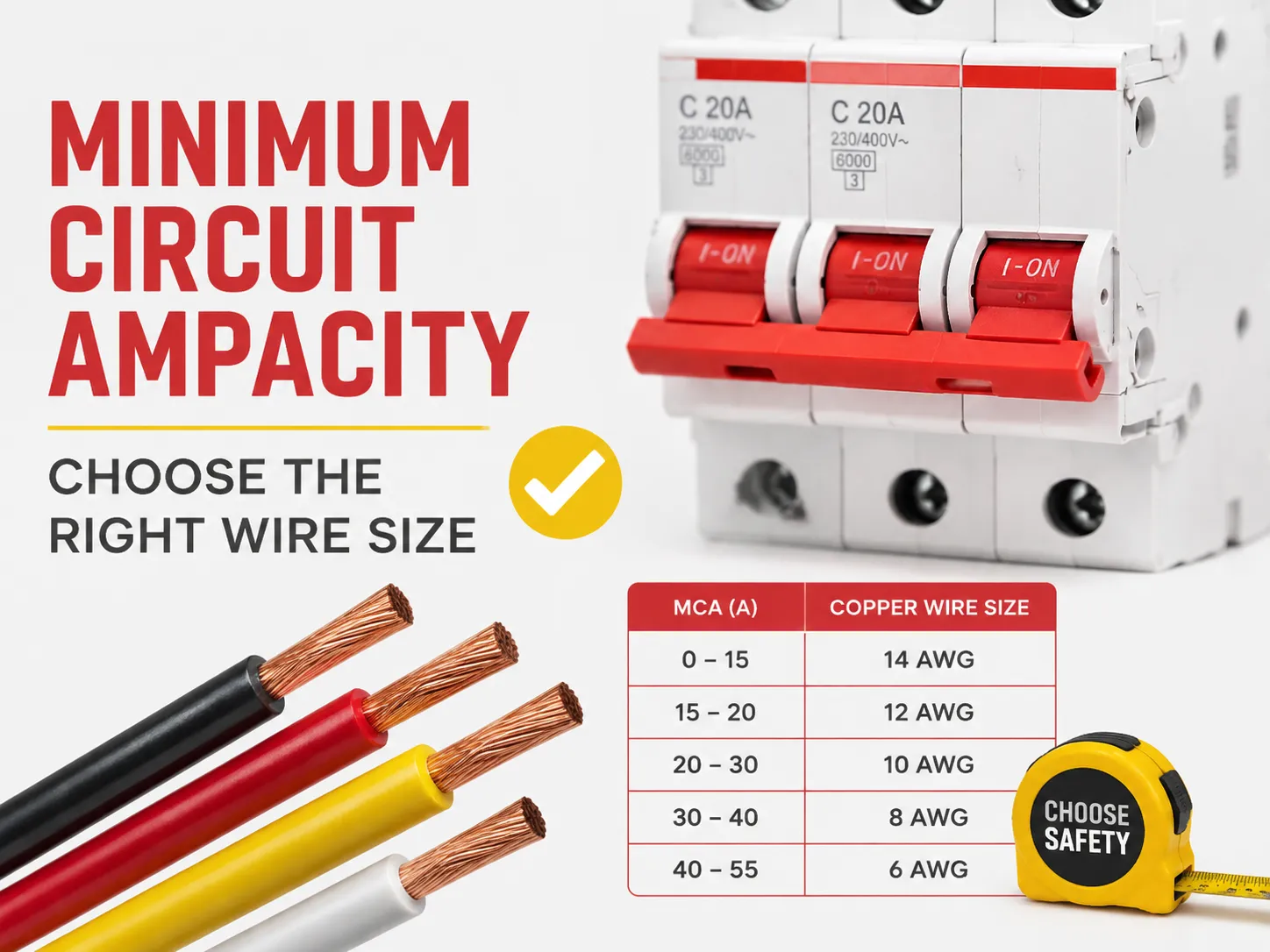
Ketika Anda memiliki MCA, memilih kawat cukup merujuk ke Tabel NEC 310.16. Gunakan kolom 75°C saat menggunakan tembaga THHN/THWN-2 (yang merupakan kawat standar untuk saluran), atau jika menggunakan NM-B (Romex) atau pengkabelan instalasi lama, gunakan kolom 60°C.
| Ukuran Kawat Tembaga (AWG) | Ampasitas @ 60°C | Ampacity @ 75°C | Menutupi MCA Hingga | Pemutus Sirkuit Tipikal |
|---|---|---|---|---|
| 14 AWG | 15 A | 20 A | 15-20 A | 15 A |
| 12 AWG | 20 A | 25 A | 20-25 A | 20 A |
| 10 AWG | 30 A | 35 A | 30-35 A | 30 A |
| 8 AWG | 40 A | 50 A | 40-50 A | 40 A |
| 6 AWG | 55 A | 65 A | 55-65 A | 60 A |
| 4 AWG | 70 A | 85 A | 70-85 A | 80 A |
| 2 AWG | 95 A | 115 A | 95-115 A | 100 A |
| 1/0 AWG | 125 A | 150 A | 125-150 A | 150 A |
| 2/0 AWG | 145 A | 175 A | 145-175 A | 175 A |
| 3/0 AWG | 165 A | 200 A | 165-200 A | 200 A |
Pilih kawat terkecil yang ampacity-nya setidaknya sama dengan ampacity terukur (setelah derating, yang dijelaskan di bawah). Untuk ampacity terukur sebesar 24,25A, kawat terkecil yang dapat digunakan adalah 12 AWG (25A). Namun, banyak pemasang menggunakan kawat yang lebih besar, seperti 10 AWG, untuk mengakomodasi jarak panjang dan/atau kebutuhan masa depan.
Layanan 200-Amp: Bisakah Anda Menggunakan Kawat 1/0?
Pertanyaan ini sering diajukan terkait dengan peningkatan layanan residensial, dan jawabannya adalah, terkait dengan layanan penuh 200A, itu adalah jawaban yang kuno tetapi salah. Dengan memperhatikan suhu 75°C, tembaga 1/0 memiliki rating maksimum 150A, dan tidak mampu menangani beban layanan 200A sesuai dengan peraturan. Jika diperlukan layanan residensial 200A, harus menggunakan salah satu jenis kawat tembaga atau aluminium berikut:
- Tembaga 2/0 yang dapat menangani 175A pada suhu 75°C. Kawat ini diizinkan untuk 200A di beberapa area (dengan Kode Komersial Khusus A).
- Tembaga 3/0 yang dapat menangani beban 200A pada suhu 75°C.
- Kawat aluminium 4/0 yang mampu memberi daya 180A pada suhu 75°C sering digunakan pada jalur masuk layanan yang memerlukan pengkabelan 200A.
Variasi lain adalah menggunakan kawat tembaga 1/0, yang hanya cocok digunakan untuk jalur layanan 150A dan hanya untuk sub-panel 150A. Hindari menggunakan kawat 1/0 dengan jalur layanan 200A karena akan terlalu panas jika digunakan dalam waktu lama. Selain itu, pastikan untuk memverifikasi dengan kode pengkabelan lokal dan inspektur karena terdapat banyak ambiguitas dalam NEC 310.12 Service Entrance.
Aturan 80% untuk Pemutus Sirkuit
Aturan NEC 210.20(A) dan 215.3 menyatakan bahwa pemutus sirkuit tidak boleh dibebani lebih dari 80% dari ratingnya. Contohnya:
- Pemutus 15A harus menangani beban kontinu hanya 12A.
- Pemutus 20A harus menangani beban kontinu hanya 16A.
- Pemutus 30A harus membawa beban kontinu hanya 24A.
- Pemutus 100A harus menanggung beban penuh hanya 80A.
Berikan perbandingan antara semua contoh di atas. Prinsip di balik regulasi ini sama dalam kedua kasus: faktor 80% dan 125% identik pada intinya yang menyatakan bahwa beban maksimum tidak boleh lebih tinggi dari kapasitas terukur perangkat dan dapat dinyatakan dalam urutan tertentu (1/1,25=0,8). Misalnya, jika perangkat digunakan dengan beban kontinu 16A, konduktor harus tahan 16*1,25=20A; oleh karena itu, pemutus tertentu harus memiliki rating untuk beban 20A, dan memang, memiliki rating hanya 20A. Ketika Anda perlu mencocokkan perangkat proteksi dengan sirkuit baru, rentang pemutus sirkuit mini bersertifikat yang dirancang untuk pekerjaan tersebut — seperti seri HUYU HUM18 MCB yang mencakup 1P hingga 4P dan kurva B/C/D — membuat pencocokan kawat ke pemutus menjadi mudah bagi pembuat panel dan kontraktor.
Derating Suhu & Pengisian Konduit
Tabel ampacity mendasarkan asumsi pada suhu lingkungan 30 derajat Celsius (86 derajat Fahrenheit), dengan tidak lebih dari 3 kabel yang melewati saluran konduit. Ketika suhu menyimpang, Anda harus menurunkan (derate) ampacity kabel sebelum membandingkannya dengan MCA.
- Suhu lingkungan tinggi: Menurut Tabel 310.15(B)(1) dari NEC, faktor koreksi dapat digunakan. Misalnya, kapasitas arus penghantar yang diberi peringkat 75°C menjadi 22A karena pada suhu lingkungan 40°C dikalikan dengan 0,88.
- Pengisian konduit: Dalam sebagian besar kasus, Tabel 310.15(C)(1) dari NEC menunjukkan faktor koreksi yang berbeda sesuai dengan jumlah kabel yang melewati konduit. Jadi, untuk 4-6 penghantar, faktor koreksi adalah 0,80; untuk 7-9 penghantar, 0,70; dan untuk 10-20 sama dengan 0,50. Dengan demikian, semakin banyak jumlah kabel menyebabkan jumlah panas yang terperangkap di dalam konduit semakin besar.
- Norma: setelah kondisi derating, ampacity baru harus tidak kurang dari MCA.
Penurunan Tegangan pada Jalur Panjang
Di sebagian besar lokasi di AS, penurunan tegangan bukanlah persyaratan kode (kecuali beberapa aplikasi) tetapi tetap berguna dan cerdas: penurunan tegangan sirkuit cabang harus 3% dan penurunan tegangan untuk seluruh feeder + cabang harus sama dengan 5%. Pedoman yang baik adalah ketika jarak lebih dari 50 hingga 100 kaki, Anda harus menggunakan ukuran kabel yang lebih besar. Jadi untuk sirkuit 120 volt dengan jarak lebih dari 150 kaki, Anda perlu menggunakan ukuran kabel yang lebih besar meskipun tabel MCA mengatakan Anda dapat menggunakan 12 AWG (10 AWG akan bekerja lebih baik). Menggunakan ukuran kabel yang salah pada jarak yang lebih panjang mengakibatkan lampu redup, motor lambat, dan panas berlebih.
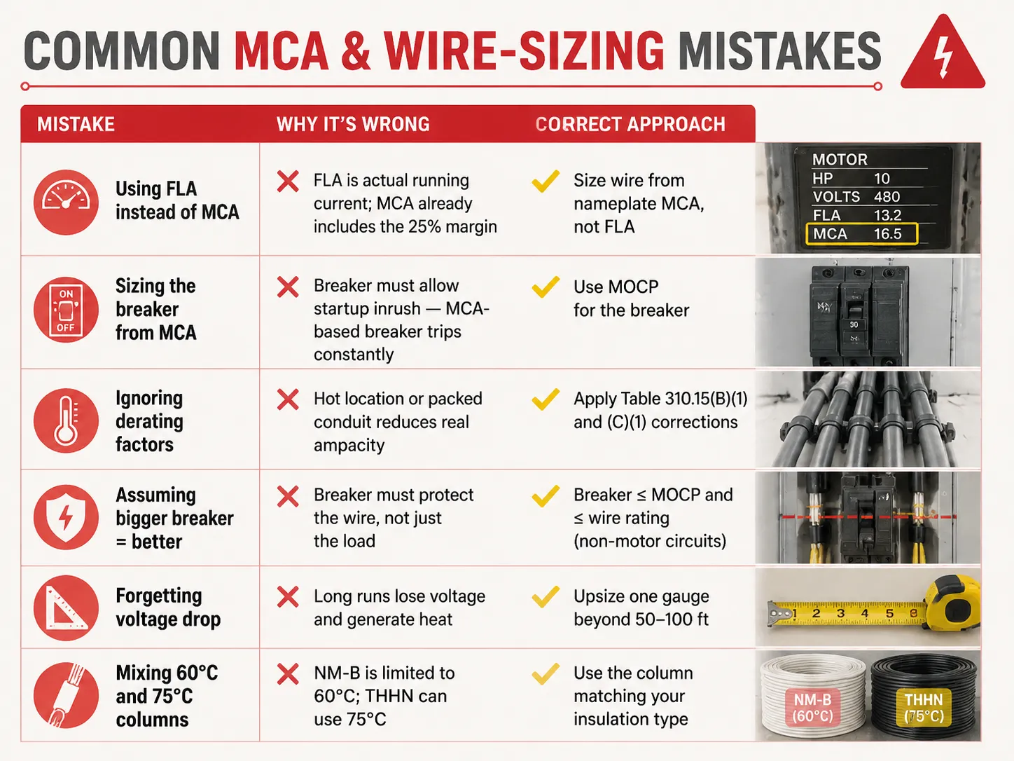
Kesalahan Umum MCA & Ukuran Kabel
| Kesalahan | Mengapa Salah | Pendekatan yang Benar |
|---|---|---|
| Menggunakan FLA alih-alih MCA | FLA adalah arus berjalan aktual; MCA sudah termasuk margin 25% | Ukur kabel dari MCA pada nameplate, bukan FLA |
| Mengukur pemutus sirkuit dari MCA | Pemutus harus mengizinkan lonjakan arus saat start — pemutus berbasis MCA sering trip | Gunakan MOCP untuk pemutus sirkuit |
| Mengabaikan faktor derating | Lokasi panas atau konduit padat mengurangi ampacity sebenarnya | Terapkan koreksi Tabel 310.15(B)(1) dan (C)(1) |
| Menganggap pemutus yang lebih besar = lebih baik | Breaker must protect the wire, not just the load | Breaker ≤ MOCP and ≤ wire rating (non-motor circuits) |
| Forgetting voltage drop | Long runs lose voltage and generate heat | Upsize one gauge beyond 50-100 ft |
| Mixing 60°C and 75°C columns | NM-B is limited to 60°C; THHN can use 75°C | Use the column matching your insulation type |
Typical MCA Values for Common Equipment
| Equipment | Typical MCA | Wire Size (75°C copper) | MOCP / Breaker |
|---|---|---|---|
| 3 HP 230V motor | ~21.3 A | 12 AWG | 30 A |
| 5 HP 230V motor | ~26.3 A | 10 AWG | 40 A |
| 10 HP 460V motor | ~17.5 A | 12 AWG | 25-30 A |
| 3.5-ton heat pump | ~22-26 A | 10 AWG | 30-45 A |
| 5-ton AC unit | ~30-35 A | 8 AWG | 45-60 A |
| Level 2 EV charger (48A) | ~60 A | 6 AWG | 60 A |
| Electric water heater (4500W/240V) | ~23.4 A | 10 AWG | 30 A |
| 200A residential service | N/A | 2/0-3/0 copper or 4/0 aluminum | 200 A main |
These are general figures — you should regularly refer to the nameplate of your unit. Also, when you are designing or enlarging your distribution installation, ensuring that the protection devices suit the cables is the kind of issue which certified equipment produced by a manufacturer ensuring the whole range addresses: understanding what a 15-amp circuit can actually carry is a good starting point, and for replacement decisions our guide on cara mengetahui apakah pemutus sirkuit buruk covers the inspection side of the story.
Pertanyaan yang Sering Diajukan
What is the 125 rule for breakers?
According to the 125% rule (NEC 210.19, 215.2, 430.22), conductors must be sized at 125% of the continuous load, or 125% of the motor’s full-load amps. In the case of the breaker, it can be seen that the same philosophy is entailed in the 80% rule, meaning that the breaker can only sustain 80% of its rating over time. Both are used to prevent overheating of the insulation. One example would be the case when the continuous load of 20A requires conductors of 25A rating (12 AWG) and a breaker rated 25A or 30A, while only 20A is used continuously in the circuit.
Can I use 1/0 wire for 200 amp service?
1/0 copper can carry 150A current at 75° C. Thus, 1/0 copper is not an appropriate option for 200A power. The right options include either 2/0 copper, good for 175A, or 3/0 copper of 200A. 4/0 aluminum can also be considered as it is good for 180A. In the case of a power of less than 150A, 1/0 copper can be successfully used. Consult a local inspector as NEC 310.12 states that service entrance has its own exceptions.
Will a 100 amp breaker accept 1/0 wire?
In most cases, if the terminal of the breaker is okay for it, then yes—most of the terminals for 100A breakers can take a wire sized up to 2/0 copper or 4/0 aluminum. However, a 100A breaker does not need a wire gauge of 1/0; the only determining thing is the load as it is what tells us what wire size to use in this instance; as an example, when the load is only 70A, then 4 AWG (85A) is the right size. It is important to read the information given on the terminals of the breaker because it is what offers all the necessary information.
What is the 80% rule for circuit breakers?
The 80% rule (NEC 210.20(A), 215.3) indicates that a breaker is limited to carrying 80% of its rating for continuous loads. For example, a 15A breaker has a continuous current maximum of 12A, whereas a 20A breaker can carry 16A and a 100A breaker can carry 80A. There is a balance in the safety margin because it mirrors the 125% rule of current rating in conductors. The full breaker rating can be used for non-continuous loads since they do not follow this rule.
Referensi
- NFPA 70 — National Electrical Code (NEC), Articles 210, 215, 240, 310, 430, 440
- OSHA 1910.303 — Electrical Systems: General Requirements
- Mike Holt — NEC Code Change Explanations (125% / 80% rules)
- EC&M Magazine — Conductor Sizing and MCA/MOCP Applications
- ENERGY STAR — HVAC Installation and Circuit Sizing Guidance
- NEMA — Motor and Electrical Product Standards
Kesimpulan
Minimum circuit ampacity provides the lowest size of wire that can be used for different types of equipment. The number is calculated based on the 125% rule by taking the largest current load or motor load multiplied by 1.25 and adding other loads to get the calculation. The wire size is determined by the MCA but the size of the breaker is determined by a separate number called MOCP. Be aware of applicable features such as the 80% rule for continuous loads, derating for heat as well as conduit fill, and voltage drop on long runs to avoid the problems of underused wires as well as wasted copper. And when a replacement breaker or panel upgrade is part of the job, understanding breaker replacement costs and the differences between protection devices like MCBs and MCCBs helps you plan the whole circuit — not just the wire.