إذا كنت قد اشتريت للتو وحدة تكييف جديدة، أو شاحن سيارة كهربائية، أو فرن تجاري، فقد يطلب منك الفني معرفة الحد الأدنى لسعة الدائرة المتاحة من لوحة الاسم. في تلك اللحظة، قد تجد نفسك تنظر إلى رقم يبدو بلا معنى بالنسبة لك. إذا ارتكبت خطأ، فقد ينتهي بك الأمر باستخدام سلك قد يكون صغير الحجم (وبالتالي – قد يسخن، يسبب انقطاعات غير مرغوبة وربما حريق)، أو قد تنفق أموالاً زائدة على توصيله بسلك كبير الحجم.
في هذا الدليل، ستتعلم ما تعنيه سعة الدائرة الدنيا، وكيف يتم حسابها، وما الفرق بين سعة الدائرة الدنيا وتحديد حجم القاطع، وكيفية تحويل هذه السعة إلى حجم السلك المناسب — مع الالتزام بلوائح NEC في العملية.
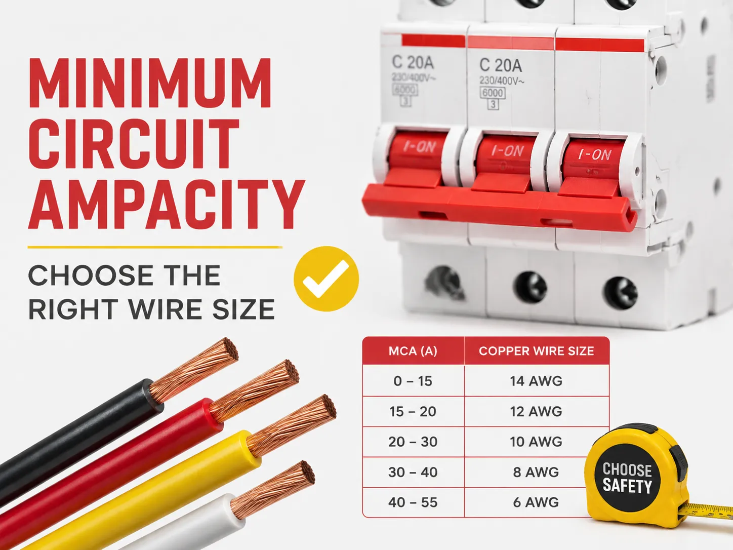
بكلمات بسيطة، MCA أو الحد الأدنى لسعة الدائرة هو الحد الأدنى لسعة السلك اللازمة لتشغيل الجهاز بشكل صحيح. لحسابه، استخدم قاعدة NEC 125%، التي تعني ضرب أكبر حمل مستمر، وهو التيار الكامل للمحرك الأكبر، في 1.25، مع جميع الأحمال الأخرى. بعد ذلك، يتم اختيار أصغر سلك يلبي أو يتجاوز هذا المطلب وفقًا لجدول NEC 310.16.
ما هو الحد الأدنى لسعة الدائرة؟
الحد الأدنى لسعة الدائرة هو أصغر قيمة محسوبة معبر عنها بالأمبيرات تظهر الحد الأدنى لسعة موصل الدائرة اللازمة لتغذية حمل دون حدوث سخونة زائدة. MCA لا تمثل كمية التيار التي يستهلكها الجهاز فعليًا في الاستخدام العادي. بدلاً من ذلك، هي متطلب أدنى مستمد من الكود لضمان وجود هامش أمان للتشغيل المستمر للدائرة ولتيار بدء التشغيل.
عمليًا، ستجد MCA على لوحات أسماء أنظمة HVAC، ومضخات الحرارة، ووحدات التبريد التجارية، وسخانات المياه، وشواحن السيارات الكهربائية، وغالبية الأجهزة التي تحتوي على محركات وعناصر تسخين. يجب على المصنعين تضمينها للامتثال للكود الذي ينص على وجوب حساب حجم السلك المناسب مع الهامش الكافي. علاوة على ذلك، فقط المنتج هو من يعرف أسوأ الحالات لتشغيل الأحمال.
النقطة الأهم هي أنه يجب الالتزام بـ MCA المطلوبة للموصل. على سبيل المثال، إذا أشارت لوحة الاسم إلى قيمة MCA بمقدار 26.4 أمبير، فيجب أن يكون السلك مصنفًا على الأقل عند هذا المستوى (أي، الالتزام بهذا المستوى بعد التعديل وفقًا لعوامل التخفيض).
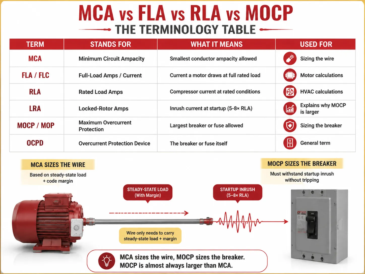
MCA مقابل FLA مقابل RLA مقابل MOCP: جدول المصطلحات
نصف الالتباس حول MCA يأتي من الحروف المختصرة المجاورة لها على لوحة الاسم. إليك ما يعنيه كل مصطلح فعليًا:
| المصطلح | يرمز إلى | ما يعنيه | يستخدم لـ |
|---|---|---|---|
| MCA | الحد الأدنى لسعة الدائرة | أصغر سعة موصل مسموح بها | تحديد حجم السلك |
| MCA | التيار الكامل للحمل / التيار | التيار الذي يسحبه المحرك عند الحمل الكامل المصنف | حسابات المحرك |
| FLA / FLC | التيار المصنف للحمل | تيار الضاغط في الظروف المصنفة | حسابات HVAC |
| FLA / FLC | تيار القفل الدوار | تيار الاندفاع عند بدء التشغيل (5-8× RLA) | يشرح سبب كون MOCP أكبر |
| RLA | الحماية القصوى من التيار الزائد | أكبر قاطع أو فيوز مسموح به | تحديد حجم القاطع |
| اضطراب الشخصية الوسواسية القهرية | جهاز الحماية من التيار الزائد | القاطع أو الفيوز نفسه | مصطلح عام |
المكون الرئيسي للنمذجة الذهنية هو أخذ عاملين مختلفين في الاعتبار في هذا الحساب — MCA و MOCP، واللذان ليسا نفس الأرقام — الأول عادة أقل من الثاني لأن القاطع يجب أن يتحمل الاندفاع في التيار عند بدء تشغيل المعدات بينما يتولى السلك التعامل مع تدفق التيار المستمر بالإضافة إلى العوامل التي تحددها الأكواد.
شرح قاعدة 125%
تكمن قاعدة 125% في أساس كل حساب لـ MCA. يمكن العثور عليها في أقسام مختلفة من NEC، وفي كل منها الهدف هو توفير هامش أمان محدد في حالة الأحمال التي تعمل بشكل مستمر أو الأحمال التي تُشغل مع تيار الاندفاع.
- NEC 210.19(A)(1) — دوائر التفرع: يجب أن تمتلك الأسلاك قدرة تيار لا تقل عن 125% من الحمل المستمر، و100% من الحمل غير المستمر. يُشار إلى الحمل بأنه “حمل مستمر” إذا كان الحمل المعني يعمل بالقيمة الكاملة لمدة 3 ساعات أو أكثر (تعريف NEC 100).
- NEC 215.2 — المغذيات: ينطبق نفس متطلب 125% أيضًا على المغذيات.
- NEC 430.22 — محرك واحد: يجب حساب الأسلاك بناءً على 125% من FLA للمحرك.
- NEC 440.22 / ممارسة الشركة المصنعة — HVAC: MCA = 125% من RLA لأكبر محرك.
لماذا 125%؟ هناك سببان لذلك. أولاً، لا حرارة مستمرة: عندما يحمل السلك التيار المقنن لفترة طويلة فإنه يسخن إلى درجة حرارته القصوى. تعني الزيادة 25% أن العزل يبقى باردًا. ثانيًا، عند بدء تشغيل أي محرك يعمل في وضع عادي يسحب عدة أضعاف التيار أثناء التشغيل الفعلي للمحرك.
كيفية حساب MCA (مع أمثلة محلولة)
للمحركات الفردية (وفقًا لكود NEC 430.22)،,
MCA = FLA المحرك × 1.25
على سبيل المثال، إذا كان هناك محرك 3 حصان، 230 فولت أحادي الطور مع FLA بقيمة 17 أمبير، إذن،,
MCA = 17 × 1.25 = 21.25 أمبير. الآن، وفقًا لجدول NEC 310.16 (عمود 75 °C)، يمكن الاستنتاج أن السلك الصغير الذي يمكنه تحمل هذه القيمة 21.25 أمبير هو 12 AWG، المصنف لتحمل قدرة تيار 25 أمبير.
لنظام الحمل المتعدد (NEC 430.24)،,
MCA = (أعلى FLA للمحرك × 1.25) + جميع SLA للمحركات الأخرى
| الحمل | FLA (أمبير) | المضاعف | المساهمة |
|---|---|---|---|
| أكبر محرك (10 حصان، 460 فولت) | 14.0 | ×1.25 | 5 أ |
| المحرك الثاني (5 حصان) | 7.6 | ×1.00 | 6 أ |
| المحرك الثالث (2 حصان) | 3.4 | ×1.00 | 4 أ |
| إجمالي MCA | 5 أ | ||
بالنسبة لـ 28.5A، يقول NEC 310.16 (75°C) أن 10 AWG نحاس (35A) هو أصغر حجم مناسب — 12 AWG (25A) سيكون صغيرًا جدًا.
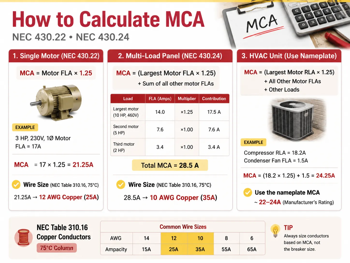
في حالة وحدة HVAC مع ضاغط ومحرك مروحة، ستكون قيم RLA المثالية كما يلي: MCA = (أكبر RLA للمحرك × 1.25) + FLAs للمحركات الأخرى + الأحمال الأخرى.
على سبيل المثال، إذا كان للضاغط RLA بقيمة 18.2 أمبير وللمروحة المكثفة FLA بقيمة 1.5 أمبير، فإننا نحصل على التالي: MCA = (18.2 × 1.25) + 1.5 = 24.25 أمبير.
يرجى ملاحظة أن هذه القيمة يتم تقريبها من قبل الشركة المصنعة إلى قيمة أكثر معيارية بين 22-24 أمبير، على لوحة اسم وحدة HVAC.
MCA مقابل الحماية القصوى من التيار الزائد (MOCP)
هنا يرتكب الهواة خطأً شائعًا: يعتقدون أن القاطع يجب أن يطابق MCA. هذا غير صحيح. يتم تصنيف القاطع وفقًا لـ MOCP، وهو مختلف عن الرقم الموجود على لوحة الاسم.
| العامل | MCA (السلك) | MOCP (القاطع) |
|---|---|---|
| ما يتم تحديد حجمه | الموصل (السلك) | جهاز التيار الزائد (القاطع/الصمام) |
| العلاقة النموذجية | الرقم الأصغر | الرقم الأكبر (يجب أن يسمح بالتيار الابتدائي) |
| يحمي من | ارتفاع درجة حرارة العزل | الدائرة القصيرة والخطأ الأرضي |
| القاعدة | قدرة التيار للسلك ≥ MCA | حجم القاطع ≤ MOCP (وفقًا لأحجام NEC 240.6 القياسية) |
| وحدة مثال | MCA 26.4A | MOCP 45A |
في هذه الحالة، يُستخدم سلك نحاسي بحجم AWG 10 (30-35A في القدرة) لتزويد الوحدة بالطاقة ويتم حمايته من الارتفاعات بواسطة قاطع 45A. هل هذا مسموح — وجود قاطع بقيمة تصنيف أعلى من السلك؟ هذا مسموح به بموجب NEC 440.22(a) لأن الضاغط لديه آليات حماية خاصة به. لذلك، في هذه الحالة، الحماية المطلوبة من القاطع هي فقط ضد الارتفاعات. ينطبق هذا على كل من أنظمة المحركات وHVAC، مع استثناء أنظمة الأسلاك العادية، حيث يجب أن يكون تصنيف قاطع الدائرة أقل من تصنيف الأسلاك.
كيفية اختيار حجم سلك AWG المناسب
عند معرفة MCA، يكون اختيار السلك ببساطة بالرجوع إلى جدول NEC 310.16. ارجع إلى عمود 75°C عند استخدام THHN/THWN-2 نحاس (وهو السلك القياسي للأنابيب)، أو إذا كنت تستخدم NM-B (Romex) أو الأسلاك في التركيبات القديمة، ارجع إلى عمود 60°C.
| حجم السلك النحاسي (AWG) | القدرة عند 60°C | السعة الأمبيرية @ 75°C | يغطي MCA حتى | القاطع النموذجي |
|---|---|---|---|---|
| 14 AWG | 15 أمبير | 20 أ | 15-20 أ | 15 أمبير |
| 12 AWG | 20 أ | 25 أ | 20-25 أ | 20 أ |
| 10 AWG | 30 أ | 35 أ | 30-35 أ | 30 أ |
| 8 AWG | 40 أ | 50 أ | 40-50 أمبير | 40 أ |
| 6 AWG | 55 أمبير | 65 أ | 55-65 أمبير | 60 أمبير |
| 4 AWG | 70 أمبير | 85 أ | 70-85 أمبير | 80 أمبير |
| 2 AWG | 95 أمبير | 115 أ | 95-115 أمبير | 100 أ |
| 1/0 AWG | 125 أمبير | 150 أ | 125-150 أمبير | 150 أ |
| 2/0 AWG | 145 أمبير | 175 أ | 145-175 أمبير | 175 أ |
| 3/0 AWG | 165 أمبير | 200 أ | 165-200 أمبير | 200 أ |
اختر أصغر سلك تكون سعته الحالية على الأقل مساوية للسعة المقدرة (بعد التخفيض، كما هو موضح أدناه). بالنسبة لسعة مقدرة تبلغ 24.25 أمبير، فإن أصغر سلك يمكن استخدامه هو 12 AWG (25 أمبير). ومع ذلك، يختار العديد من المثبتين سلكًا أكبر، مثل 10 AWG، لاستيعاب المسافات الطويلة و/أو الاحتياجات المستقبلية.
خدمة 200 أمبير: هل يمكنك استخدام سلك 1/0؟
يُطرح هذا السؤال غالبًا فيما يتعلق بترقيات الخدمة السكنية، والإجابة هي أنه بالنسبة لخدمة 200 أمبير كاملة، فإن الجواب لا صحيح ولكنه قديم. مع مراعاة درجة حرارة 75°C، فإن سلك النحاس 1/0 سيكون له تصنيف أقصى يبلغ 150 أمبير، ولن يكون قادرًا على التعامل مع حمل خدمة 200 أمبير وفقًا للقانون. إذا كانت هناك حاجة لتحقيق خدمة سكنية 200 أمبير، فيتطلب ذلك استخدام أحد أنواع أسلاك النحاس أو الألمنيوم التالية:
- 2/0 نحاس يمكنه التعامل مع 175 أمبير عند درجة حرارة 75°C. يُسمح باستخدام هذا السلك لـ 200 أمبير في بعض المناطق (مع رمز تجاري خاص A).
- 3/0 نحاس يمكنه التعامل بنجاح مع حمل 200 أمبير عند 75°C.
- سلك ألمنيوم 4/0 قادر على تغذية 180 أمبير عند 75°C وغالبًا ما يُستخدم في خطوط مدخل الخدمة التي تتطلب توصيل أسلاك 200 أمبير.
خيار آخر هو استخدام سلك نحاس 1/0، وهو مناسب للاستخدام فقط في حالة خطوط خدمة 150 أمبير، وشحن لوحة فرعية 150 أمبير فقط. تجنب استخدام سلك 1/0 مع خط خدمة 200 أمبير بأي ثمن لأنه يسخن كثيرًا عند التشغيل لفترة طويلة. بالإضافة إلى ذلك، تأكد من التحقق مع كود الأسلاك المحلي والمفتش لأن هناك العديد من الغموض في NEC 310.12 مدخل الخدمة.
قاعدة 80% لقواطع الدائرة
تنص قواعد NEC 210.20(A) و215.3 على أنه لا يجب تحميل قاطع الدائرة بأكثر من 80% من تصنيفه. على سبيل المثال:
- يجب أن يتحمل قاطع 15 أمبير حملًا مستمرًا لا يتجاوز 12 أمبير فقط.
- يجب أن يتحمل قاطع 20 أمبير حملًا مستمرًا لا يتجاوز 16 أمبير فقط.
- يجب أن يحمل قاطع 30 أمبير حملًا مستمرًا لا يتجاوز 24 أمبير فقط.
- يجب أن يتحمل قاطع 100 أمبير حملًا كاملاً لا يتجاوز 80 أمبير فقط.
قدم مقارنات بين جميع الأمثلة أعلاه. المبدأ وراء التنظيم هو نفسه في كلتا الحالتين: عامل 80% و125% متطابقان في جوهرهما، حيث يدعيان أن الحمل الأقصى لا يجب أن يتجاوز السعة المقدرة للجهاز ويمكن التعبير عنه بترتيب معين (1/1.25=0.8). على سبيل المثال، إذا تم استخدام الجهاز بحمل مستمر 16 أمبير، يجب أن يتحمل الموصل 16*1.25=20 أمبير؛ وبالتالي، يجب أن يكون القاطع المحدد مصنفًا لحمل 20 أمبير، وفي الواقع، هو مصنف فقط لـ 20 أمبير. عندما تحتاج إلى مطابقة أجهزة الحماية مع دائرة جديدة، فإن مجموعة قواطع الدائرة المصغرة المعتمدة المصنفة للعمل — مثل سلسلة HUYU HUM18 MCB التي تغطي 1P إلى 4P ومنحنيات B/C/D — تجعل مطابقة السلك مع القاطع سهلة لبناة اللوحات والمقاولين.
تخفيض السعة حسب درجة الحرارة وملء المواسير
يعتمد جدول الأمبيرية على افتراض درجة حرارة محيطة تبلغ 30 درجة مئوية (86 درجة فهرنهايت)، مع عدم مرور أكثر من 3 أسلاك عبر قناة التوصيل. عندما تنحرف درجة الحرارة، يجب تخفيض (خفض) الأمبيرية للسلك قبل مقارنتها مع MCA.
- درجة الحرارة المحيطة العالية: وفقًا للجدول 310.15(B)(1) من NEC، يمكن استخدام عوامل التصحيح. على سبيل المثال، تصبح قدرة التيار المسموح بها للموصل المصنف لـ 75°C هي 22A لأنه عند درجة حرارة محيطة 40°C يتم ضربها في 0.88.
- تعبئة القناة: في معظم الحالات، يشير الجدول 310.15(C)(1) من NEC إلى عوامل تصحيح مختلفة حسب عدد الأسلاك المارة عبر القناة. وبالتالي، بالنسبة لـ 4-6 موصلات، يكون عامل التصحيح 0.80؛ ولـ 7-9 موصلات، يكون 0.70؛ ولـ 10-20 يكون مساويًا لـ 0.50. وبالتالي، يؤدي العدد الأكبر من الأسلاك إلى احتجاز كمية أكبر من الحرارة داخل القناة.
- المعيار: بعد حالة التخفيض، يجب ألا تقل الأمبيرية الجديدة عن MCA.
هبوط الجهد في المسافات الطويلة
في معظم المواقع في الولايات المتحدة، لا يُعتبر هبوط الجهد مطلبًا في الكود (باستثناء بعض التطبيقات) ولكنه لا يزال مفيدًا وذكيًا: يجب أن يكون هبوط جهد دائرة الفرع 3% ويجب أن يساوي هبوط الجهد للدائرة الكاملة + الفرع 5%. إرشاد جيد هو عندما تكون المسافة أكثر من 50 إلى 100 قدم، يجب استخدام حجم سلك أكبر. لذلك، بالنسبة لدائرة 120 فولت تمتد لأكثر من 150 قدمًا، تحتاج إلى استخدام حجم سلك أكبر حتى لو قال جدول MCA أنه يمكنك استخدام 12 AWG (سيؤدي 10 AWG إلى أداء أفضل). استخدام سلك بحجم خاطئ على مسافات أطول يؤدي إلى إضاءة خافتة، ومحركات بطيئة، وارتفاع درجة الحرارة.
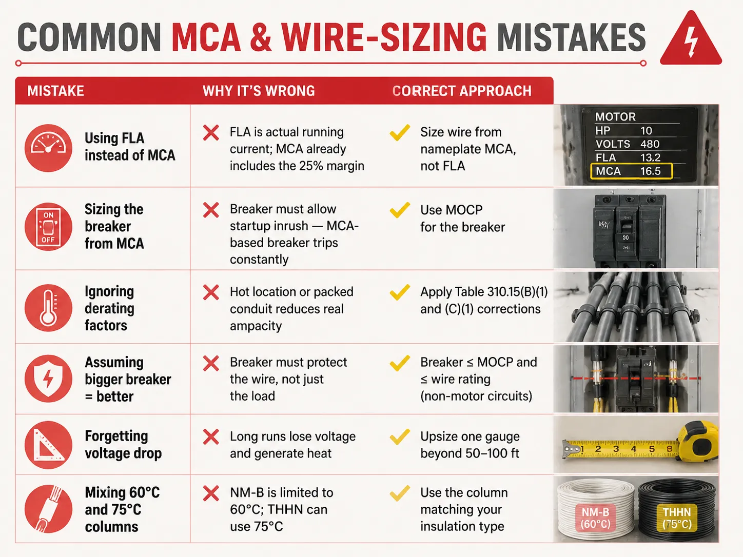
أخطاء شائعة في MCA وتحديد حجم السلك
| الخطأ | لماذا هو خطأ | النهج الصحيح |
|---|---|---|
| استخدام FLA بدلاً من MCA | FLA هو التيار الفعلي أثناء التشغيل؛ MCA يشمل بالفعل هامش 25% | تحديد حجم السلك بناءً على MCA الموجود على لوحة الاسم، وليس FLA |
| تحديد حجم القاطع بناءً على MCA | يجب أن يسمح القاطع بتيار بدء التشغيل — القاطع المبني على MCA ينقطع باستمرار | استخدم MOCP للقاطع |
| تجاهل عوامل التخفيض | الموقع الحار أو القناة المعبأة يقللان من الأمبيرية الحقيقية | تطبيق تصحيحات الجدول 310.15(B)(1) و(C)(1) |
| افتراض أن القاطع الأكبر = أفضل | Breaker must protect the wire, not just the load | Breaker ≤ MOCP and ≤ wire rating (non-motor circuits) |
| Forgetting voltage drop | Long runs lose voltage and generate heat | Upsize one gauge beyond 50-100 ft |
| Mixing 60°C and 75°C columns | NM-B is limited to 60°C; THHN can use 75°C | Use the column matching your insulation type |
Typical MCA Values for Common Equipment
| المعدات | Typical MCA | Wire Size (75°C copper) | MOCP / Breaker |
|---|---|---|---|
| 3 HP 230V motor | ~21.3 A | 12 AWG | 30 أ |
| 5 HP 230V motor | ~26.3 A | 10 AWG | 40 أ |
| 10 HP 460V motor | ~17.5 A | 12 AWG | 25-30 A |
| 3.5-ton heat pump | ~22-26 A | 10 AWG | 30-45 A |
| 5-ton AC unit | ~30-35 A | 8 AWG | 45-60 A |
| Level 2 EV charger (48A) | ~60 A | 6 AWG | 60 أمبير |
| Electric water heater (4500W/240V) | ~23.4 A | 10 AWG | 30 أ |
| 200A residential service | غير متاح | 2/0-3/0 copper or 4/0 aluminum | 200 A main |
These are general figures — you should regularly refer to the nameplate of your unit. Also, when you are designing or enlarging your distribution installation, ensuring that the protection devices suit the cables is the kind of issue which certified equipment produced by a manufacturer ensuring the whole range addresses: understanding what a 15-amp circuit can actually carry is a good starting point, and for replacement decisions our guide on كيفية معرفة ما إذا كان القاطع معطلاً covers the inspection side of the story.
الأسئلة الشائعة
What is the 125 rule for breakers?
According to the 125% rule (NEC 210.19, 215.2, 430.22), conductors must be sized at 125% of the continuous load, or 125% of the motor’s full-load amps. In the case of the breaker, it can be seen that the same philosophy is entailed in the 80% rule, meaning that the breaker can only sustain 80% of its rating over time. Both are used to prevent overheating of the insulation. One example would be the case when the continuous load of 20A requires conductors of 25A rating (12 AWG) and a breaker rated 25A or 30A, while only 20A is used continuously in the circuit.
Can I use 1/0 wire for 200 amp service?
1/0 copper can carry 150A current at 75° C. Thus, 1/0 copper is not an appropriate option for 200A power. The right options include either 2/0 copper, good for 175A, or 3/0 copper of 200A. 4/0 aluminum can also be considered as it is good for 180A. In the case of a power of less than 150A, 1/0 copper can be successfully used. Consult a local inspector as NEC 310.12 states that service entrance has its own exceptions.
Will a 100 amp breaker accept 1/0 wire?
In most cases, if the terminal of the breaker is okay for it, then yes—most of the terminals for 100A breakers can take a wire sized up to 2/0 copper or 4/0 aluminum. However, a 100A breaker does not need a wire gauge of 1/0; the only determining thing is the load as it is what tells us what wire size to use in this instance; as an example, when the load is only 70A, then 4 AWG (85A) is the right size. It is important to read the information given on the terminals of the breaker because it is what offers all the necessary information.
What is the 80% rule for circuit breakers?
The 80% rule (NEC 210.20(A), 215.3) indicates that a breaker is limited to carrying 80% of its rating for continuous loads. For example, a 15A breaker has a continuous current maximum of 12A, whereas a 20A breaker can carry 16A and a 100A breaker can carry 80A. There is a balance in the safety margin because it mirrors the 125% rule of current rating in conductors. The full breaker rating can be used for non-continuous loads since they do not follow this rule.
المراجع
- NFPA 70 — National Electrical Code (NEC), Articles 210, 215, 240, 310, 430, 440
- OSHA 1910.303 — Electrical Systems: General Requirements
- Mike Holt — NEC Code Change Explanations (125% / 80% rules)
- EC&M Magazine — Conductor Sizing and MCA/MOCP Applications
- ENERGY STAR — HVAC Installation and Circuit Sizing Guidance
- NEMA — Motor and Electrical Product Standards
الخلاصة
Minimum circuit ampacity provides the lowest size of wire that can be used for different types of equipment. The number is calculated based on the 125% rule by taking the largest current load or motor load multiplied by 1.25 and adding other loads to get the calculation. The wire size is determined by the MCA but the size of the breaker is determined by a separate number called MOCP. Be aware of applicable features such as the 80% rule for continuous loads, derating for heat as well as conduit fill, and voltage drop on long runs to avoid the problems of underused wires as well as wasted copper. And when a replacement breaker or panel upgrade is part of the job, understanding breaker replacement costs and the differences between protection devices like MCBs and MCCBs helps you plan the whole circuit — not just the wire.