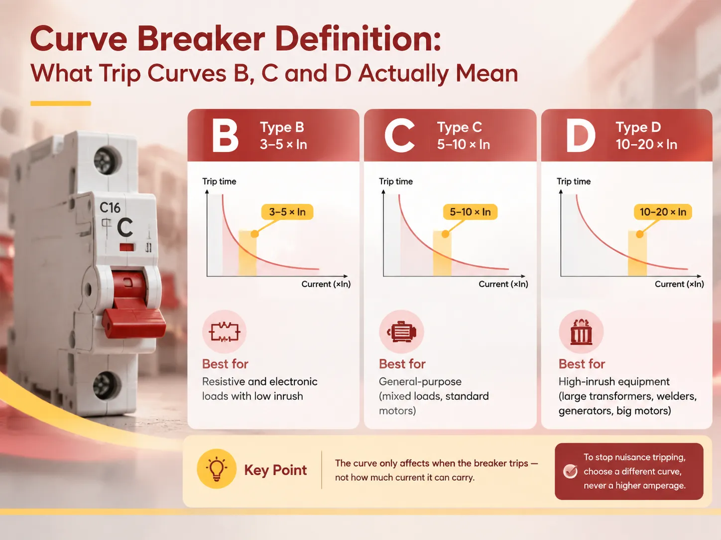
A curve breaker may not be a new kind of breaker but refers to a breaker whose trip time is determined by a curve that has been preset so that it allows the circuit to trip every time a motor is switched on or stay closed when a wire is burning. It is easy to be mistakenly confused since the title does not have anything to do with current but with the speed of breaker’s reaction to a certain rate of its rated current. So no matter what the amperage value is, breaking the wrong curve would mean that there is no solution to the problem, which is why the same annoying trip that has an engineer looking for a larger breaker can be easily solved only if one letter in its name is changed. This manual provides a definition of the trip curve, gives descriptions of the curves and the trip levels, as well as explains why it is necessary to select them properly.
To summarize, a curve breaker is a specific kind of circuit breaker that uses standard curves (labeled with B, C, or D); each curve displays the time-current trip characteristic, which indicates the setting of the magnetic trip valve. The different types of circuit breakers have different trip settings based on the In current. The trip current of the curve breaker is defined below in a table where the B-type breaker should trip at 3 to 5 times In, C-type at 5 to 10 times In, and D-type at 10 to 20 times In, according to the IEC/EN 60898-1 standard. The thermal characteristics are the same for all 3 types of breakers; however, the instantaneous trip current differs. Thus, for example, B-type breakers could be used with electronic loads having low inrush current, the C-type breaker can be used with loads of mixed type and normal motors, and finally the D-type breaker is meant for heavy inrush equipment.
What “Curve Breaker” Means
This phrase describes a circuit breaker type that operates according to a pre-set time-current characteristic rather than a single point in time when it trips its switch. Each thermal magnetic miniature circuit breaker has its own “curve.” The “curve” is the name of the term that defines how this equipment behaves when subjected to various currents.
There are two mechanisms responsible for this process. The first is a thermal device – a bimetallic strip that is heated by current flowing through it. If overload occurs, the strip bends gradually until it trips; thus, it has both a protective meaning against slow overheating of wiring and operates according to a curve that is called inverse-time as it gets faster with increases in overload, though not instantly. The second mechanism is a magnetic device, or solenoid that increases the force applied to the circuit with the rise of current. This is how the instantaneous part of the curve is achieved.
As both mechanisms are used for the same contact mechanism, the “curve” represents how these two mechanisms behave altogether: the smooth inverse-time slope at low current values where the thermal device works and almost vertical decrease in this part of the curve when the magnetic device takes control. The point where the curve turns vertical is the value defined by its letter.Devices built to this principle, and the families they belong to, are covered in our guide to MCB and MCCB selection.
Practical meaning is that the curve does not represent a quality or a current rating. Both the Type B breaker 20A and the Type D breaker 20A carry 20A throughout and protect a circuit of 20A. The only difference between the two breakers is how much current they can tolerate for short durations.
Anatomy of a Trip Curve
A trip curve is represented using log-log axes. The horizontal axis is the current as a ratio of the rated current; that is, I/In. The vertical axis is the tripping time, which is expressed in seconds from thousands of seconds to milliseconds.
| Region of the curve | Current range | Mechanism | What it protects against |
|---|---|---|---|
| No-trip region | Up to about 1.13 × In | Neither element operates | — normal load current |
| Indeterminate thermal band | 1.13-1.45 × In | Thermal; may or may not trip within the specified time | Marginal overload |
| Definite thermal trip | Above 1.45 × In | Thermal, inverse time | Cable overload and overheating |
| Magnetic transition | 3-5× (B), 5-10× (C), 10-20× (D) | Magnetic, instantaneous | Short circuit and high inrush discrimination |
Instead of looking at the data in the table in terms of safety, they should be treated as a story of discrimination. The thermal region is exactly the same for each of the curves since cable protection is a common issue regardless of the type of load. It is in the magnetic region that it is for the manufacturer to decide whether the device should trip in case of low current in a way that sensitive equipment is protected but all acceptable inrushes of current are ignored or vice versa – to trip late allowing for all inrush currents accepting that the device will react to real overcurrent faults slower. The letter of the curve is the record of this choice.
An important point should be made clearly as it shows the practical relevance of the whole issue of curving selection. The inrush current is a real and quite normal phenomenon. A common AC induction motor takes from five to eight times its rated current during a very short period right after its start. A transformer when connected to the grid may consume from ten to fourteen times its rated current during the first cycles. If the value of the current is lower than any of those readings then the device trips every time even when the fault is absent. The same logic should be applied to control contacts along with protection devices, as they perform switching but no fault elimination.
The Standard Curves
IEC/EN 60898-1 defines the three curves used in the overwhelming majority of domestic and light commercial installations.
| Curve | Magnetic trip threshold | Typical trip time at threshold | Designed for | Common applications |
|---|---|---|---|---|
| Type B | 3-5 × In | 0.1 s and below at the upper end | Loads with minimal inrush | Lighting circuits, resistive heating, socket outlets in domestic work, PLC and instrumentation supplies, control circuits |
| Type C | 5-10 × In | 0.1 s and below at the upper end | Inductive and mixed loads | Standard motors, pumps, fans, HVAC, commercial socket circuits, general industrial distribution |
| Type D | 10-20 × In | 0.1 s and below at the upper end | Very high inrush | Large transformers, welders, X-ray equipment, generators, large motors, cranes and lifts, compressors |
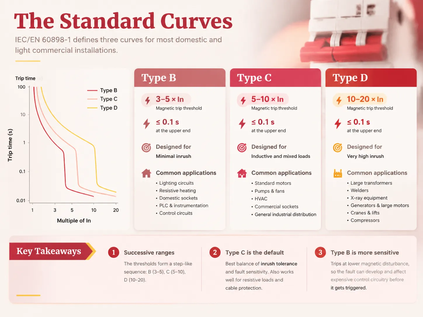
An effective way to keep track of the hierarchy is that the number ranges tend to be more or less successive, meaning that the curves resemble a series of steps in the tolerance. In B, the number of times the rating can jump is around three to five, while in C this number ranges from five to ten and in D from ten to twenty. Above the threshold, everything reacts nearly instantly, below the threshold though everything has to be processed through the slower thermal agent if it can be processed at all.
There are two points regarding Type C that are worth noting. First, Type C is in fact the default option for most of the commercial and production equipment in the industry because it is good enough in terms of the balance between the inrush tolerance level and the fault sensitivity level. In addition, it is not a bad option for a resistive load because it still works well for cable protection. The main reason to use Type B is the sensitivity factor: it will trip lower magnetic disturbance and therefore be capable of letting the fault develop and affecting the expensive control circuitry before the Type B device gets triggered.
Other Curves and Variants
B, C and D are the standard set, but several other characteristics exist for specific problems.
| Curve | Magnetic threshold | Intended use |
|---|---|---|
| Type A | 2-3 × In | Semiconductor and electronic loads requiring very sensitive short-circuit protection; short circuits in long cable runs |
| Type Z | 2-3 × In | Electronics and control circuits where sensitivity is the priority; comparable to Type A with a different standard lineage |
| Type K | 8-12 × In | Motors, transformers and equipment with high inrush where Type D would be excessively insensitive |
| Type MA | Magnetic only, around 12 × In | Motor circuit protection where overload is handled by a separate overload relay; no thermal element |
| Adjustable curves (MCCB) | Field-adjustable | Moulded-case breakers where the curve and rating are set to the installation and can be coordinated with upstream devices |
The difference between device families is important for this reason as the available curves will depend on the standard used for manufacturing the breaker. Miniature circuit breakers compliant with IEC 60898-1 use fixed curves with no possibility of adjustment from any of those in B, C, or D families. Moulded-case circuit breakers that comply with IEC 60947-2, on the other hand, commonly have the opportunity for some adjustment of magnetic and thermal settings, which creates scope for sychroisation throughout the distribution system as opposed to fixed options. The decision between the device families relates to rating, fault level, and adjustments not to the curve selection.
B Curve vs C Curve
This is the most common practical comparison, and the answer turns almost entirely on inrush.
| Type B | Type C | |
|---|---|---|
| Magnetic trip band | 3-5 × In | 5-10 × In |
| Response to a 6 × In surge | Trips instantaneously at the upper part of the band | May tolerate it; trips only above 5 × depending on the individual device |
| Sensitivity to genuine faults | Higher — detects lower-magnitude short circuits | Lower — a low-magnitude short may be left to the thermal element |
| Risk on a motor circuit | High risk of nuisance tripping at every start | Appropriate in most cases |
| Risk on a lighting or electronics circuit | None; appropriate | Possible missed detection of a developing fault |
| Typical specification | Domestic lighting, sockets, control panels, instrumentation | Motors, pumps, HVAC, general commercial and industrial distribution |
It is noteworthy that there is an overlap between the two bands: A device located at the mid-point of the Type B band (4 × In), for example, is not far removed from one positioned at the lower limit of the Type C band (5 × In), and in fact the bands should be viewed as ranges, not as precise points, due to manufacturing tolerances. This is the reason why nuisance tripping can sometimes be avoided simply by changing the manufacturer, not the curve, even though the proper course of action would be to use the right curve from the manufacturer’s published information.
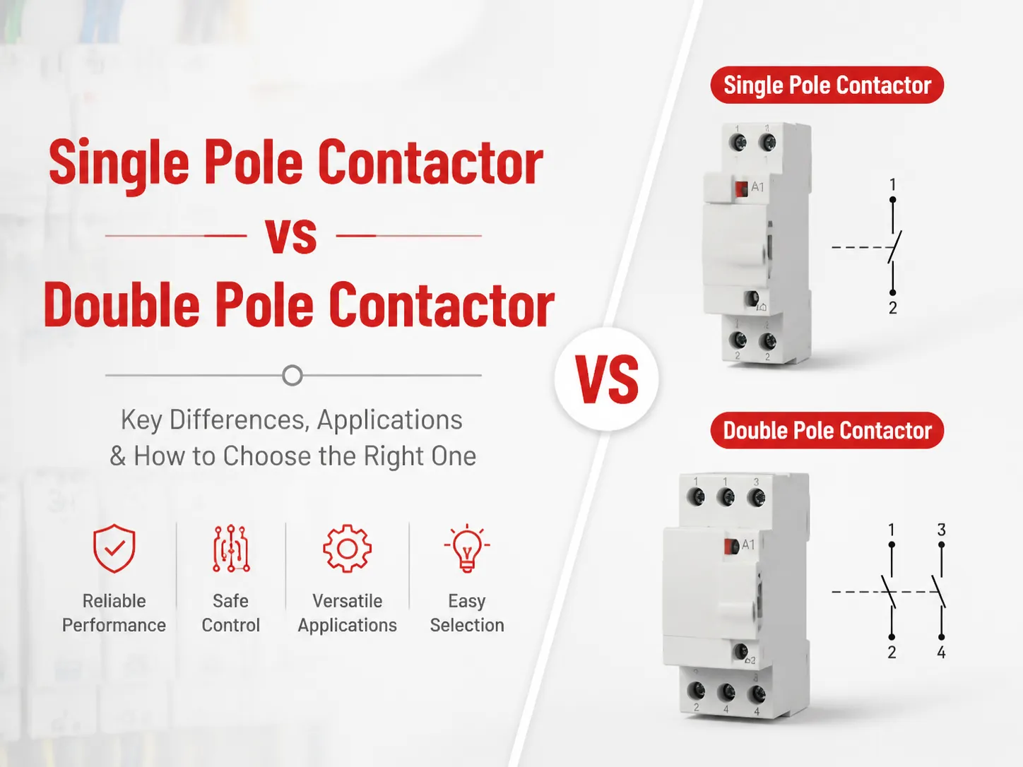
Where a load is close to a boundary — such as a motor that starts with a current right on the edge of a Type C band — the specification must be verified against the actual starting current data for the equipment regardless of the values used in the calculations. In fact, selecting a curve on the basis of the rule of thumb and then finding out after commissioning that it does not work is probably the most common reason why a panel has to be opened.The same principle of matching device to load applies to pole configuration, and the selection logic for that is set out in our guide to single-pole and double-pole breakers.
The “AC Curve” Question
There is no “AC curve” definition in IEC 60898-1, and it is important to clarify that because the term is used in practice. The term “AC curve” usually refers to one of the following two things.
- The first thing is the classification of a breaker that is rated for AC and not for DC. This is a valid point but relates to the rating of the device rather than the classification itself. AC and DC breakers have different designs, as it is much harder to extinguish an arc using the DC circuits. This is because the current does not reach zero two times in one cycle, so there is no natural point where the arc becomes extinguished. As a result, the DC-rated breaker has a different design of arc chutes, contacts, and magnetic systems, including different curves that are published. Using an AC rated breaker in a DC circuit is the result of an application error rather than the curve mistake.
- The second meaning of this term is a misunderstood Type C in conversation. This confusion is easy in a busy workshop and also across the linguistic border.In cases where there is an actual DC application — solar arrays, batteries, DC traction, telecom power — the appropriate DC rating and curves should be used, and polarity might also be important. Overall, if a specification mentions “AC curve,” one should just find out what it actually means and confirm the ratings for the device before placing an order.
How to Select a Curve
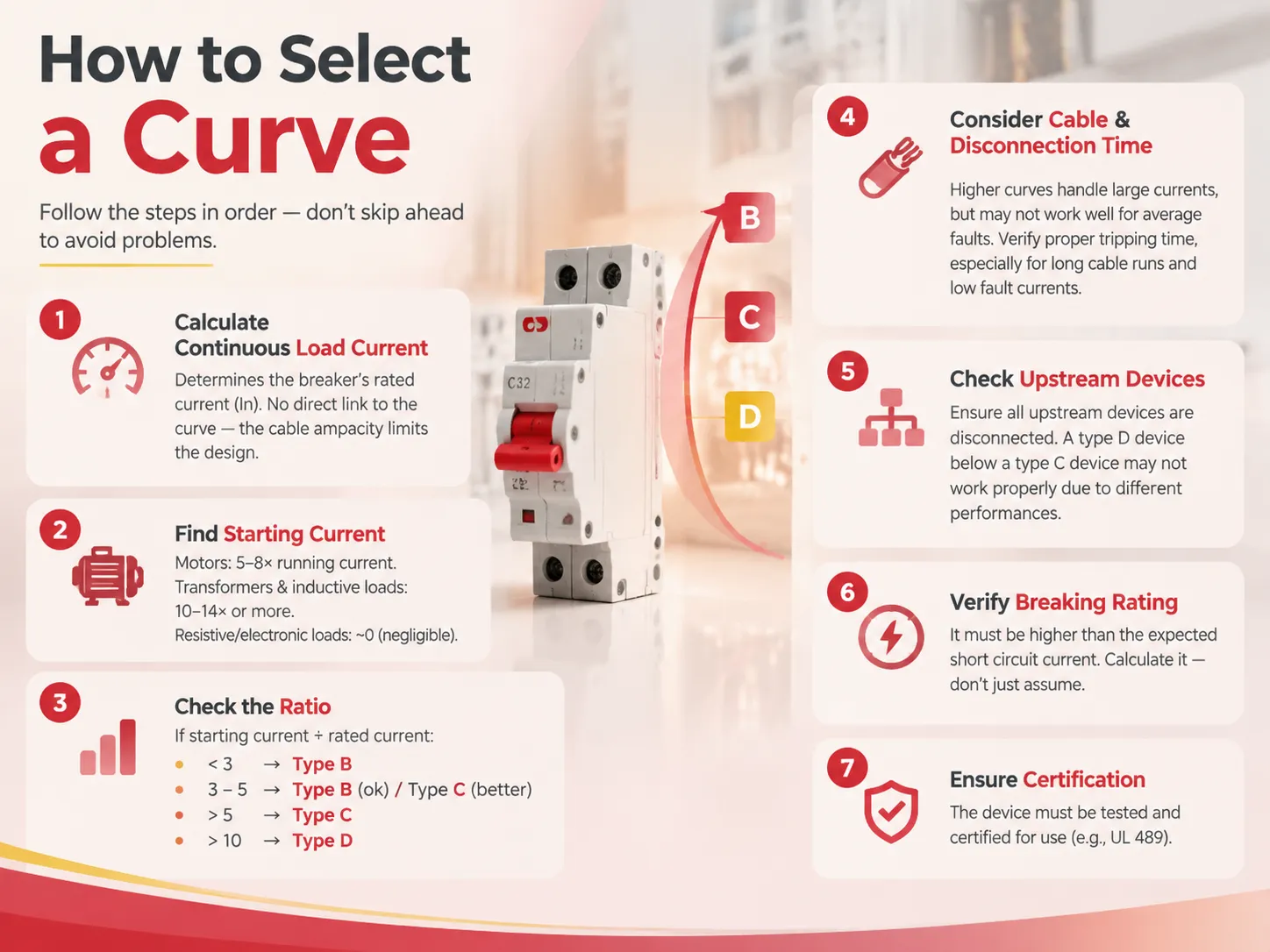
The process of selecting the appropriate curve is a simple procedure. It should be carried out sequentially because skipping curve selection ahead of cable size estimation is a potential source of problems.
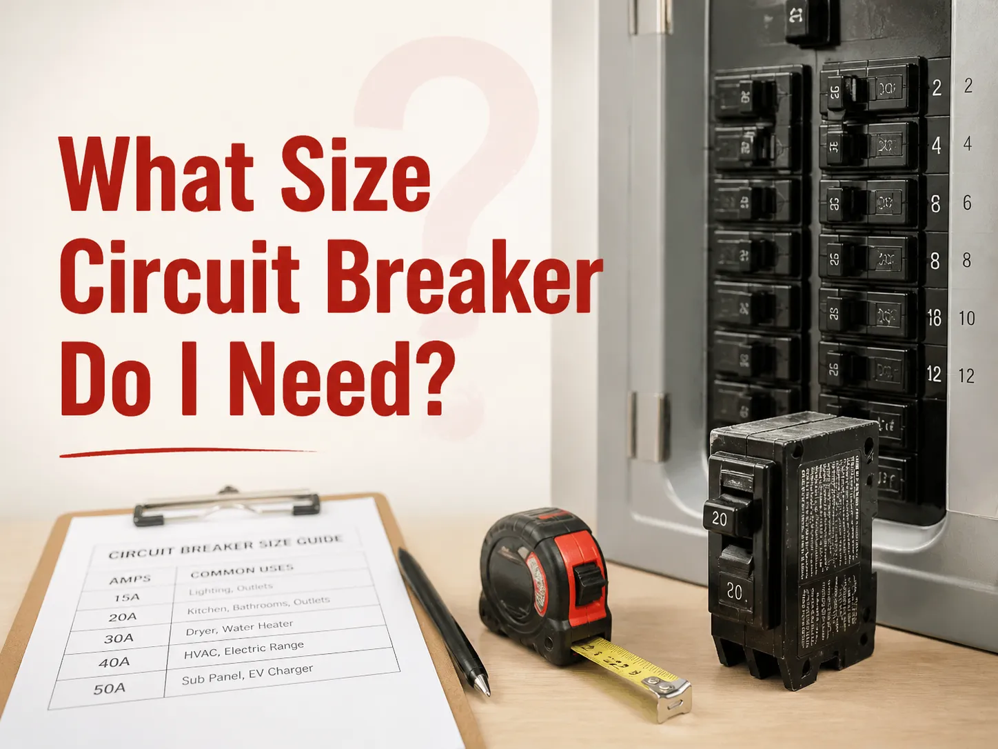
- Calculate the continuous load current. This determines the value of rated current (In) of the breaker, but it has no connection with the curve of the device. The breaker is designed to protect the cable, which means that cable ampacity is the limiting factor in the process.
- Find the values of starting current of all members of the circuit. In the case of motors it would be equal to five to eight times running current, while transformers and similar types of inductive loads may produce current of 10 to 14 and more times than rated current. Contribution from resistive and electronic loads can be neglected, since it would be equal to almost zero.
- Calculate the ratio of starting current to rated current. If the ratio is below three times rated current, the curve type B is suitable to deal with this issue. If the ratio is between three and five, type B can be employed but type C would be a more reliable choice. If the ratio is higher than five, type C is the best option. If the calculation shows a ratio higher than ten times, the curve of type D should be applied.
- Make sure to consider the type of cable and the disconnection time. Higher curve types work better with large currents, but at the same time they do not function properly in case of average fault currents. Verify that the circuit disconnection takes place at the right time even in the case of low fault current value, especially in case of long cable runs.
- Make sure that all upstream devices above this device in the circuit are disconnected while using this particular breaker. In the case of the type D device installed below type C device in the circuit, they may not function properly due to different performances of the two types under defined fault current.
- Check if the breaking rating is higher than the expected short circuit current to be met at the installed location. It is recommended not to assume the value of this current, but calculate it instead.
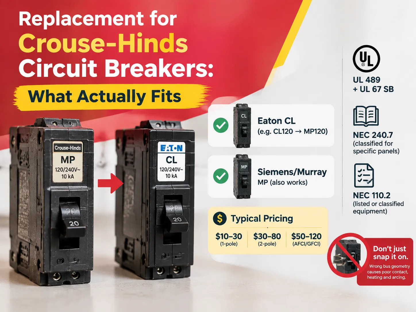
- Make sure that the device has passed testing and is certified for use. The following topics are covered in our article regarding UL 489 certification.
Once the correct curve is known, the remaining selection is straightforward. A manufacturer offering B, C and D curves across a single certified product family simplifies both specification and spares holding; the HUM18-63N range, available from 1P to 4P at up to 63 A in B, C and D curves, is an example of that structure and illustrates the specification detail a buyer should expect.
Ambient Temperature and Derating
When it comes to devices that follow IEC 60898-1, the curve identifies behaviour at a reference temperature, generally at 30°C. This is due to the fact that the overload element operates on thermal basis, and as a result, its performance changes along the changes in temperature around it, and this is a common reason of unexpected tripping in installations.
In the case of a hot environment, e.g. for a panel during a hot day, a distribution board in a box exposed to sun, or a breaker next to equipment that produces heat, the bimetallic strip has a higher starting point and reaches its trip point at lower current, which is significant, as manufacturers have tables showing how devices with 20A operating at 60°c would carry a much lesser current, and vice versa, when the unit is functioned at lower temperature level, it would trip at a higher current level.
There are three things worth mentioning. First, when placing devices in warm spots one may select breaker rating based on derating tables data rather than nominal value, which may indicate the need to pick a higher rating. Second, devices installed close together in panels impact each other by means that the manufacturer’s factor has to be added to the ambient correction. Third, if circuit trips only on hot afternoons, it is rather a case of derating issue as opposed to the fault in operation. Where a device is genuinely suspect, the diagnostic approach in our guide to identifying a failed breaker is the place to start.
Common Mistakes
- Increasing ampacity rather than modifying the curve is the most severe mistake in this field. Installing a 32 A circuit breaker within a circuit wired using a 20 A electric cable implies that the wires may get hot and insulation may deteriorate before the circuit breaker even operates. In essence, the circuit breaker offers protection to the wire more than to the load.
- Installing type D circuit breakers in less specific situations. Type D has the capacity to withstand inrushes but allows moderate fault currents for longer periods which may go unnoticed in susceptible circuits. Type D circuit breakers should only be used for high inrushing situations.
- Ignoring ambient correction factor. Sometimes a seemingly correct device may turn out to be wrong due to high temperatures.
- Mistaking B, C and D across different manufacturers. There are standards for the bands, but that does not mean that tolerances and the shape of curves remain the same; so it is wise to check the curves manufactured by a specific manufacturer rather than use the approximate values.
- Using an AC-rated device on DC current. Direct current requires much more complicated processes.
- Neglecting coordination. Even if devices are correctly selected they still may trip incorrectly because of coordination error.
- Selecting a curve prior to selecting a cable. The cable defines the rating of the circuit breaker, and the load determines the curve; otherwise, the installation may appear to have followed the rules while not being safe at all.
Standards and Certification
Which standard applies determines which curves exist, what the device is tested to, and what the markings mean.
| Standard | Applies to | Curve characteristics |
|---|---|---|
| IEC/EN 60898-1 | Miniature circuit breakers for household and similar installations | Fixed B, C and D curves with defined magnetic bands; domestic and light commercial |
| IEC/EN 60947-2 | Circuit breakers for industrial installations, including MCCBs | Often adjustable thermal and magnetic settings; used where coordination across a system is required |
| UL 489 | Moulded-case circuit breakers for the North American market | Uses different trip-band conventions; devices are not interchangeable with IEC curve types |
| UL 1077 | Supplementary protectors | Not branch-circuit protective devices; must not be substituted for a UL 489 breaker |
The North American distinction causes buyers who operate in multiple markets difficulty. A device that is labeled as “Type C” per IEC 60898-1 and a device that has a C-something catalog number per UL 489 are not the same thing and operate with different trip characteristics. This is particularly important when a single project crosses standards, such as a European panel that must be installed on a North American site: the certification is determined by the law at the installation site, which means that the device must be certified accordingly. The same rationale applies to the auxiliary functions provided by some of these devices: the certification must match the panel, not the catalog name.
FAQ
What does it mean to be a curve breaker?
This implies that the behavior of the circuit breaker in terms of tripping is based on a published time-current curve instead of one fixed trip value. Such a curve gives information on the operating time of the device for each multiple of rated current, giving the bottom line about the two types of tripping: a slow thermal one which protects conductors against overloading and instantaneous magnetic one which protects against short circuits. The letter indicating the type of circuitry on the device – B, C or D according to IEC 60898-1 – indicates the multiple to which the particular device belongs: 3-5, 5-10 and 10-20 times of rated current, respectively. The working principle of the curve is to determine the trip time rather the maximum current the device can carry.
What are the three types of breakers?
The standard types in the IEC 60898-1 family are three. The first type is type B with its magnetic trip range of 3 to 5 times the rated current; type C with a magnetic trip of 5 to 10 times rated current; and type D of 10 to 20 times rated current. The type B is suitable for loads that have minimal or negligible inrush, such as lighting, resistance heating, socket outlets and control instruments. Type C is the preferred type for mixed loads and for normal motors which makes it the most frequently used specification in commercial and industrial distribution. Type D is used for equipment that has big inrush loads, like large transformers, welders, generators, X-ray machines and big motors. Apart from these three types, there exist the types A, Z and K designed for specific applications and modern molded circuit breakers usually come with adjustable settings as opposed to fixed ones.
What does the AC curve breaker mean?
The term “AC curve” does not specifically exist in the IEC 60898-1 standard. In reality, “AC curve” could refer to either of two meanings. For example, it can relate to a device rated for AC service instead of DC service since breaking of arcs is considerably more difficult for DC due to the constant flow of electrical current. Devices rated specifically for DC operations have specially developed devices such as arc chutes and contacts. An “AC curve” could also mean type C as a result of malapropism or misunderstanding. It is important to be cautious when using this term since any order needs to indicate the intended meaning of “AC curve”. For application which actually requires working in DC mode such as photovoltaic solar cells or battery storage it is critically important to rely strictly on the devices that are rated for DC operations and use DC curves only by the manufacturers.
What’s the difference between B curve and C curve breakers?
The distinction comes down to the magnetic tripping curve. A Type B breaker trips at 3-5 times its rated current, whereas Type C trips at 5-10 times. In all other regards — that is, thermal overload mechanism, continuous current capacity, and size — they are practically identical. In practice, Type B is more sensitive, which is why it is good at identifying emerging fault conditions in low-inrush circuits; however, it also trips in case of motor startup. Type C is capable of withstanding the five to eight times inrush current produced by the motor while still being sufficiently sensitive for general use. Therefore, it tends to be the default circuit breaker in industrial and commercial installations. In theory, it is not that one type of circuit breaker is better than the other; any of them is appropriate for operating in its own conditions.
Can I fix nuisance tripping by fitting a bigger breaker?
No, this task is very dangerous to do. The amperage rating of a breaker is based on the current-carrying capacity of the wires it protects (typically a 15 A circuit is connected to 14 AWG wires, while a 20 A circuit is normally wired with 12 AWG cables). This means that connecting a 32 A breaker to a 20 A wire may result in an overheating wire which has no protection against overheating and may catch fire. Whenever there is a nuisance tripping problem on the motor circuit, one should rather consider it a curve problem than a rating issue and fix the issue by going from Type B to Type C or from C to D (if the inrush can justify this), while verifying the result on the actual inrush value rather than on speculation.
References
- International Electrotechnical Commission — IEC 60898-1 Circuit Breakers for Household and Similar Installations
- International Electrotechnical Commission — IEC 60947-2 Circuit Breakers for Industrial Installations
- UL Solutions — UL 489 Molded-Case Circuit Breakers and UL 1077 Supplementary Protectors
- BSI — BS EN 60898-1 Requirements for MCB Trip Characteristics
- NFPA — National Electrical Code, Article 240 Overcurrent Protection
Conclusion
A curve breaker is merely a certain kind of breaker with its particular behaviour being identified by a curve, the only thing that varies with different curves being the current value at which magnetic device will operate. Type B operates at three to five times the nominal current and is appropriate for the loads whose launch is close to smooth; Type C at five to 10 times and is appropriate for the motor and mixed loads dominating typical installations; Type D at 10-20 and exists for transformers, welding machines, and huge equipment emitting such a pulse that the correctly selected breaker would trip all the time. The thermal overload response of all the devices is the same; that’s the point that removes any confusion since it is evident that the curve is about the inrush discrimination and not about the protection capability. In order to avoid nuisance tripping, just define the cable rating, the curve based on the load’s inrush curve, check that the above selected device reacts in short time in case of the lowest fault current, use derating factors and check the coordination with upstream devices.