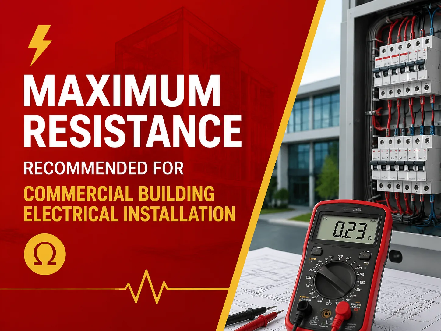
A person comes to perform electrical inspection in your commercial building. The engineer informs him that the ground electrode was tested at 22 Ohms. Someone nearby says that since NEC permits 25 Ohms, everything is okay. But the equipment manufacturer’s handbook states that 5 Ohm max is needed since it works with sensitive electronics; therefore, the commissioning engineer cites a specification that is new for you. Which value needs to be followed? The question posed is very common for those who work in the commercial electrical field, but the answer depends on the standard you are measuring against.
This piece of writing shows you the answer right away with the exact numbers that are right – no imaginary numbers will be used. You will get to know what exactly NEC requires, what IEEE says, how the “25 Ohm rule works,” and what is regarded as safe.
If you are looking for a quick answer, then there is no clear cut number that is universally applicable for maximum resistance of grounding in all commercial buildings because this answer depends on which standard and which part of the system you mean. The NEC (NFPA 70) does not have a general maximum resistance of a building, but rather the combination of 25 ohms (which is actually specified in 250.53) contains practical sense when talking about the grounding rod or plate only and is only used to see if 1 rod or plate is enough for the grounding electrode (that is, if 1 electrode is 25 ohms or below it is fine to not use the second one). For the large commercial and industrial systems, IEEE’s Std 142 (“Green Book”), specifies that the primary grounding electrode’s resistance to the earth must be in the range of 1-5 ohms, and the practice of the industry (NFPA/ IEEE recommendations, NETA ATS practices, telecom industry standards, etc.) aims to have around 5 ohms for commercial buildings and even 1 ohm for substations and generating stations. To put it together, NEC’s minimal requirements are not related to the performance required by IEEE in terms of range of values of 1-5 ohms for commercial buildings that has been commonly accepted as a target value in the industry while anything above 25 ohms is seen as poor and unacceptable in commercial grounding electrode.
Let’s be precise, because this is where misinformation lives. The relevant numbers, with their sources:
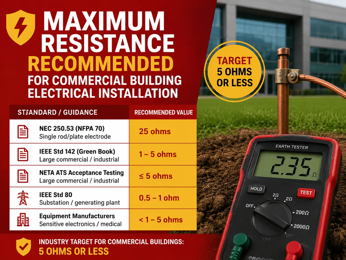
| Standard / Guidance | Value | What It Applies To |
|---|---|---|
| NEC 250.53 (NFPA 70) | 25 ohms | Single rod/plate electrode — if resistance tests at 25Ω or less, a second electrode isn’t required |
| NEC 250.53 default | Two electrodes | Rod/pipe/plate electrodes default to two; no 25Ω test needed when both are installed |
| IEEE Std 142 (Green Book) | 1–5 ohms | Recommended earth resistance of the main grounding electrode for large commercial/industrial systems |
| IEEE Std 80 | 0.5–1 ohm | Substation / generating plant grounding grids |
| NFPA/IEEE industry guidance | 5 ohms or less | Commonly cited commercial target; telecom industry standard |
| NETA ATS acceptance testing | 5 ohms / 1 ohm | ≤5Ω large commercial/industrial; ≤1Ω generating/transmission stations |
| Equipment manufacturers | <1 to 5 ohms | Sensitive electronics / medical diagnostic equipment specs |
Important fact: there is no requirement in the NEC that a commercial ground must be “25 ohms or less”. The number 25 is included only to decide if there is sufficient spacing from only one electrode. Performance requirements like IEEE 142 and NETA recommendations and practice suggest a value between 1 and 5 ohms – with 5 ohms being the most commonly used limit.
The NEC 25-Ohm Rule — What It Really Means
According to NEC Section 250.53(A)(2) (as well as 2005 NEC Section 250-56), the code requires the installation of two grounding electrodes. However, there is an important exception stating that a single electrode is permitted if it meets the required resistance to ground of 25 ohms or less.Unfortunately, this is often misinterpreted as meaning that one can install one electrode only, test its resistance, and then add the second electrode in case the first didn’t meet the resistance requirement of 25 ohms.
Actually, the breakdown is as follows:
- Default = two electrodes installed at least 6 feet apart.
- Allowed = single electrode subjected to a proper resistance test verifying that the resistance to ground is 25Ω or less.
In the event that the second second electrode is installed, the combination does not have to fulfill the 25-ohm condition — as the second electrode is regarded as having complied with the NEC requirements by being installed.
IEEE 142 (Green Book): The 1–5 Ohm Recommendation
The query, “what is the recommended resistance for a commercial structure?” receives an authoritative engineering solution from IEEE Std 142, known as the Green Book. The suggestion it makes is an earth resistance of 1 to 5 ohms for the main grounding electrode in large industrial and commercial systems.
The reason for preferring this value of resistance over 25 ohms is that commercial facilities are often equipped with sensitive electronics, etc., and thus need very stable and low impedance ground reference, which is not sufficient with just code minimum. Having low ground resistance noted above allows:
- Higher fault current returning to the source faster
- Less voltage rise on the equipment case during the fault
- Better lightning surge dissipation
- Less electrical noise
To sum it up, code requires 25 ohms; in engineering terms, 1-5 ohms is the value needed for good performance.
Industry Practice: 5 Ohms as the Commercial Target
In the field, the information most people are likely to hear for commercial systems is “5 ohms or less.” This comes from various different but complementary sources, such as:
- the recommendations of NFPA and IEEE for 5.0 ohms or less as a good target
- the approaches in telecommunications (5 ohms or less for grounding and bonding)
- the NETA’s standards for acceptance tests (≤5 ohms for commercial/industrial systems; ≤1 ohm for power plants/transmission stations)
- the figures given by different equipment manufacturers (from 1 to 5 ohms for delicate electronics)
According to the common recommendation of different engineers and testers, 5 ohms or less is good for commercial buildings, while the average value for substations is 1 ohm and less. This is not a requirement by NEC, but it is the best practices that many designers follow and that are subject to testing.
Is There a Safe Range? Understanding the Numbers
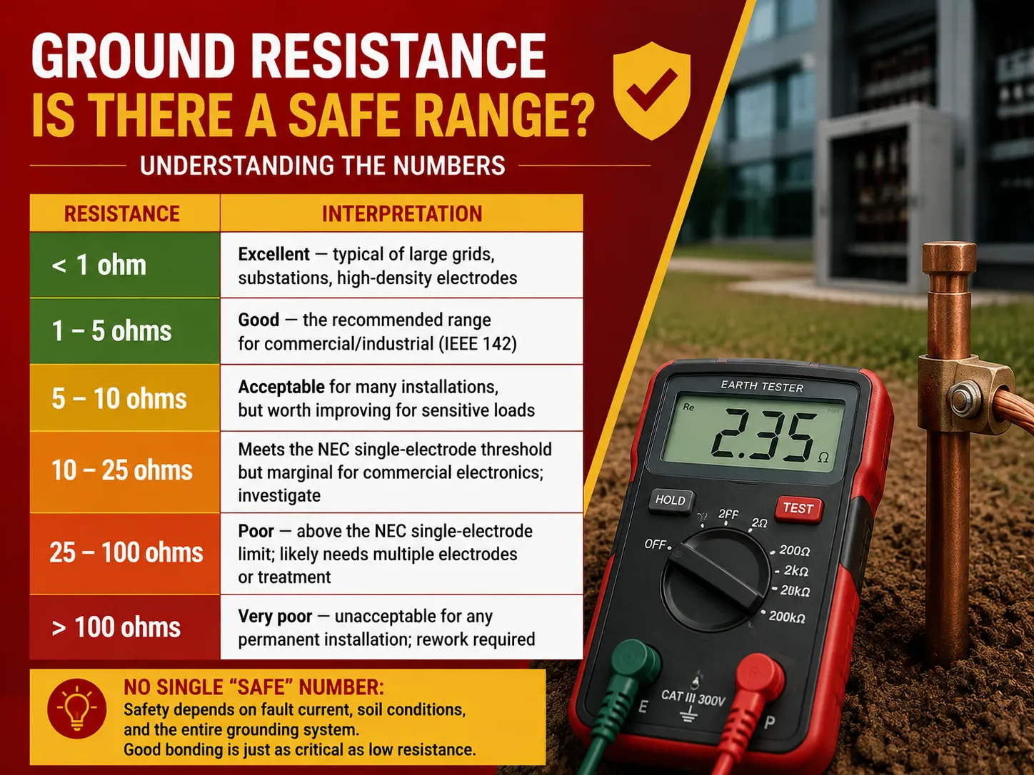
Here’s how to interpret ground resistance readings in practice:
| Resistance | Interpretation |
|---|---|
| < 1 ohm | Excellent — typical of large grids, substations, high-density electrodes |
| 1–5 ohms | Good — the recommended range for commercial/industrial (IEEE 142) |
| 5–10 ohms | Acceptable for many installations, but worth improving for sensitive loads |
| 10–25 ohms | Meets the NEC single-electrode threshold but marginal for commercial electronics; investigate |
| 25–100 ohms | Poor — above the NEC single-electrode limit; likely needs multiple electrodes or treatment |
| > 100 ohms | Very poor — unacceptable for any permanent installation; rework required |
The key warning is as follows: there is not one universal “safe” value that applies to each situation from a safety perspective — it is also influenced by different factors such as earth fault current, soil conditions and the actual circuit. The quality of electrode grounding resistance is only a part of the problem; the integrity of the whole grounding system is just as important. A perfect electrode of 2 Ohm is useless if the ground conductors of the devices are crooked or corroded.
Is 20 Ohms Bad? Interpreting Your Measurement
20-ohm resistance levels are not viewed positively in the commercial building construction code, but there are also no code violations associated with that value, hence:
- NEC standard: This level is less than the maximum single-electrode value determined by the above legislation. Nevertheless, 20-ohm resistance level is still close to exceeding the standards, depending on the seasonal increase and decline of moisture level in the soil.
- IEEE 142 standard: Based on this standard, the resistance level of 20 ohm exceeds the recommended value of 1-5 ohm, meaning that some of the electronic equipment, such as those preventing surge operations, might be damaged because of the improper grounding level.
In practical terms, any commercial organization will make sure the grounding meets the set standards.
Conclusion: Generally speaking, 20 ohm of resistance may not threaten the life of the building, but it is still too high for a commercial building; therefore, it needs to be improved.
Other Commercial Requirements: Receptacles & Bonding
The ground resistance is a part of commercial electrical safety. The National Electrical Code (NEC) requirements are as follows:
- The characteristics of commercial receptacles (NEC 406, 210.52, 210.8): The commercial receptacles shall be specified to be 125V,15A and/or 20A types, GFCI protection is necessary to be provided at certain locations (bathrooms, rooftops, kitchens, outdoor locations etc. per 210.8(B)), all the receptacles will be connected to the metal box and each receptacle shall be ensured to be connected to the grounding conductor.
- Bonding process (NEC 250.102-250.104): It is essential to understand that all the metallic parts which can become energized like piping, framed equipment, structural steel, pumping equipment must be bonded to the grounding system. It’s worth noting that bonding continuity testing will be carried out separately from electrode resistance (point-to-point resistance should not exceed 0.5 ohm when equipment is connected to the grounding system).
- Grounding electrode conductor (NEC 250.66): The grounding electrodes must be sized according to the service doesn’t exceed the maximum diameter and should connect the grounding system to the service equipment.
If you’re also verifying the protective devices on the circuit, our explanation of circuit breakers vs ground-fault circuit interrupters clarifies which protection does what in a commercial panel.
What Counts as High Electrical Resistance?
Context plays a role in what “high resistance” means:
- When measuring grounding electrodes, it means greater than about 25 ohms (for instance, 100 ohms or greater is a very high value). The “ideal” resistance level is 1-5 ohms.
- In terms of continuity of grounding, anything more than 0.5 ohm indicates a fault. The connection between equipment and ground should be almost zero.
- With respect to insulation resistance, a high resistance value means a good resistance since it is measured in mega and gigohms where anything below 1 MΩ indicates a high probability for a breakdown.
In conclusion, “high resistance” almost always means a problem (for grounding) but it can mean a good situation (for insulation). Always make sure what exactly one is talking about when using a term “high resistance”.
Factors That Affect Ground Resistance
Ground resistance is not a constant value. It varies with circumstances:
- Soil resistivity: Clay/loam (10–100 Ω·m) has lower resistivity than sand/gravel (1,000–10,000 Ω·m).
- Moisture content: Wet soils have lower resistivity while dry weather increases resistance enormously.
- Temperature: Cold soil has much higher resistivity.
- Electrode depth and cross section: Longer electrodes and bigger plates go deeper into soil.
- Number of and separation between electrodes: The more electrodes you have and the farther apart they are, the lower the resistance will be.
- Electrode material and corrosion: The longer the electrodes stay in the ground, the more corrosion there is, and resistance will increase.
How to Achieve a Low-Resistance Ground
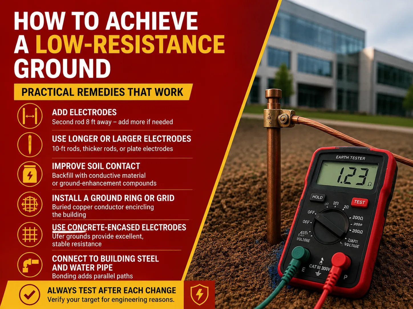
In case your commercial grounding is excessively high, here’s a ranked list of the most cost-effective solutions:
- Add rods: Adding a second ground rod, placed 8 feet away from the first, will greatly reduce the resistance. Continue adding additional rods until the correct resistance is achieved (the benefit generated decreases with each added rod).
- Use larger or longer rods: Using a longer rod (10-foot) or thick rods or plate electrodes will help reach deeper and less resistant soils.
- Improve soil connection: Backfilling conductive materials or chemical additives around the rod will improve its connection with the soil.
- Create ground rings or grid: Underground copper conductor encircling the structure creates a bigger area of connection (this solution is widely used in commercial/industrial field).
- Use concrete-encased electrodes (Ufer grounds): Concrete-embedded rebar and conductor show excellent and reliable conduction properties.
- Connect to the building’s steel parts and water pipe: Connecting to the metal structural steel and underground water pipes (if any) gives additional ways of conduction.
Be sure to test every time you change the system, but keep in mind that the NEC does not require retesting the two-electrode system.
How Ground Resistance Is Tested
Ground testing is to be carried out by persons qualified for this job. The main and widespread methods are:
- Fall-of-Potential (more commonly known as three-point testing): The fall-of-potential method consists in the use of two temporary stakes and resistance measuring with increasing distance. It is the most precise technique used for small to medium installations.
- Clamp-on (or inductive) testing: The clamp-on method involves the clamp around the rod/conductor so that the loop resistance can be measured without disconnecting the loop. It is advantageous for the already existing installations but requires the whole loop connected.
- Two-point testing: The two-point method is used to make fast measurements against a known reference electrode: this technique is less accurate, thus used in rough calculations.
Testing is dangerous, since it usually requires isolation of the electrode, and fault current may be present, this job should not be done by an ordinary homeowner. For commercial buildings the commissioning and regular tests usually are performed by contractors or specialized companies in accordance with NETA standards.
Frequently Asked Questions
Which guideline outlines the acceptable maximum resistance for earthing in commercial installations?
NEC does not specify a single standard maximum value. The 25-ohm requirement outlined in NEC 250.53 applies only to the case of a single-electrode system, and not to the whole building. A major engineering standard is IEEE Std 142 (the Green Book), which suggests that the value of the main grounding electrode in large commercial and industrial installations should be in the range of 1-5 ohms. Normally, in practice, and accepting standards set by NETA, the value of 5 ohms is satisfactory for a commercial building (1 ohm for a substation). In general, NEC shows the limit according to the requirements of the code, IEEE 142 provides the acceptable range according to the engineering requirements, and then 5 ohms emerges as the accepted practice.
Is 20 ohms of resistance in a ground bad?
A resistance of 20 ohms is not hazardous in itself but is borderline acceptable for commercial buildings. While the NEC’s single-rod criterion of 25 ohms is passed, the number is above the level recommended by IEEE 142 for commercial installations, which is 1-5 ohms, as well as the commonly accepted level of 5 ohms. With that level of grounding, the fault current is returning in a slower manner and not providing remarkable surge protection or reference grounding for sensitive electronics as well. And since it is just a step away from going above the code threshold, the level may go up as a result of soil condition changes during the seasons. Hence, the grounding system should be improved in the case of commercial installations.
What are the NEC commercial receptacle requirements?
All commercial receptacles have a voltage rating of 125 volts to 15 or 20 amps as stated in NEC 406, and their minimum amount and spacing rules can be found in 210.52 for general areas. GFCI protection is mandatory in given commercial spaces under NEC 210.8(b), such as bathrooms, kitchens, rooftops, outdoors, and garages/service areas. All receptacles must be provided with an equipment grounding, and metallic boxes are to be grounded. In many commercial child-occupied places, tamper-resistant receptacles are a must, while some types of occupancies have their particular rules for provided receptacles.
What is a high electrical resistance?
“High electrical resistance” depends upon what measurement is at hand. With regard to grounding electrodes, anything over approximately 25 ohms counts as high, while numbers over 100 ohms are considered very high. Ideally, the resistance should be somewhere between 1 and 5 ohms. Concerning equipment grounding continuity, the electrical resistance should not exceed 0.5 ohm when measuring the equipment and the ground. In insulation, a high resistance is a positive sign. For insulation to be considered healthy, it must have a resistance of millions of ohms (MΩ) or even billions of ohms. A resistance level of less than 1 MΩ indicates a breakdown with leakage danger.
References
- NFPA 70 — National Electrical Code (NEC), Article 250 (Grounding & Bonding), 210.8, 406
- IEEE Std 142-2007 — Recommended Practice for Grounding of Industrial and Commercial Power Systems (Green Book)
- IEEE Std 81 — Guide for Measuring Earth Resistivity, Ground Impedance, and Earth Surface Potentials
- NETA — Acceptance Testing Specifications (ATS) for electrical power equipment
- Vertiv — Why Test Grounding Systems (NEC/IEEE 142/80 grounding values)
- Fluke — Ground resistance testing application notes
Conclusion
The NEC’s two figures — 25 ohms and 1-5 ohms as per the IEEE 142 guide cover the maximum allowed electrical ground resistance of a commercial building. While the NEC does not consider for a commercial building the value of under 25 ohms that would indicate compliance with the code as a performance standard, it depends on whether a single electrode is sufficient. From this standpoint, the ideal value for reliable and safe performance of commercial installation would be in the range of 1-5 ohms, as noted by IEEE, thus facilitating fast failure elimination, effective surge protection, low noise level for commercial electronics.
Use proper fall-of-potential testing to get a good measurement and tally it against the range table (as good value is under 5, value ranging from 5 to 25 is marginal, value over 25 is below the acceptable level); you may need to add more or longer electrodes to the grounding system unless you find the readings satisfactory. Finally, do not forget that the resistance of electrodes is only half of the story and the continuity of bonding and grounding must also be accounted for.