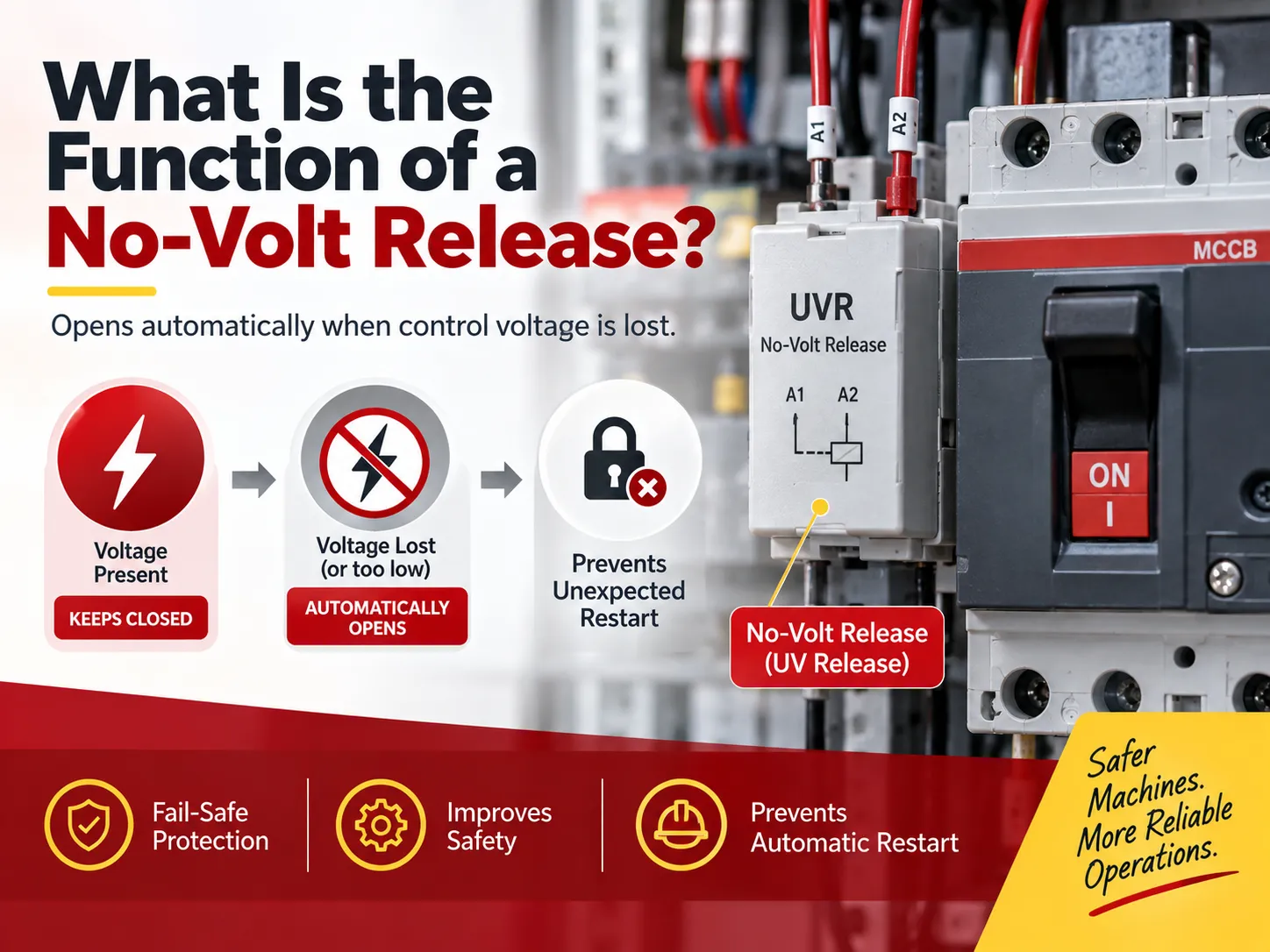
A no-volt release provides an answer to a question that every control panel manufacturer and machine designer must ask themselves at one point: “What will happen if power comes off and comes back on?” Saying that “the machine starts all by itself” is not acceptable for machines with rotating knives, loaded conveyors, and pressure pumps. The no-volt release (sometimes called a no-voltage coil or an undervoltage release (UVR)) maintains the position of “I will remain OFF until told to do so.” This device is also the least expensive safety device in a control panel and also one of the most misunderstood devices because the same function is done quite differently depending on whether a contactor or circuit breaker is being used. This guide contains information about no-volt releases, their operation, their applications, how they differ from shunt trips, their alternatives, the need for no-volt releases, and how to specify and test a no-volt release so that you do not fall into the coil-voltage trap.
To summarize, the purpose of a no-volt release is to ensure that a switching device remains in the closed position as long as control voltage is supplied; if control voltage shuts off, the equipment automatically opens, as per the IEC/EN 60947-2 standard, when the loss of the control voltage falls below 35% of its rated value; in contrast, in the range of 35% to 70% rated voltage, there are no levels where it can automatically open, and above 70%, there will be no automatic opening. A no-volt release inhibits automatic restart of the equipment following a loss of supply since, once power is restored following power loss, restart can occur when voltage is restored to about 85% of rated value.
The Core Function
The one-sentence version of this is that the no-volt release makes the supply of control voltage a condition of the control remaining on. But, there are four different functions and it is good to clarify what they are since various projects will require different functions.
Preventing Unexpected Restart. This is the main purpose of the no-volt release and where it gets its name from. When there is a failure in the supply, then everything after this point is stopped. However, the danger comes from the seconds after the supply resumes. The classic accident that the no-volt release is meant to prevent is when a saw, mixer, conveyor or machine tool becomes live again while the operator’s hands are still in the machine. The no-volt release will prevent the circuit from closing until the person performing the operation presses the start button. It is important to have this in machinery standards and is a necessity for the majority of industrial machines.
Creating an Automatic Shut Down Under Sustained Voltage. Motors will not operate well when there is a lower voltage. Individual motors will draw more electricity at lower voltages in order to produce the same amount of work and cause greater heat in the wires, where there could be a breakdown of the insulation and failure of the equipment. The role of the undervoltage relay (UVR) will open the circuit so that there will not be a thermal failure.
Creating a Hardwired Safety Chute. Because the no-volt release operates in relation to the lack of voltage when there is normal supply voltage, every safety device can be used as a means to create an emergency shut down. A safety switch, pull cord switch, fire alarm switch, or contact with the building management system naturally produces an opening of the circuit. Anything that breaks the line creates a safe shutdown. This behavior is known as “fail-safe.”
Confirming Healthy Voltage Before Closing. In the case of generator transfer schematics, there will be nervousness at closing the switch if there is no voltage. The UVR will allow for confirmation that there is healthy voltage (greater than 85% of the rated voltage).
How It Works
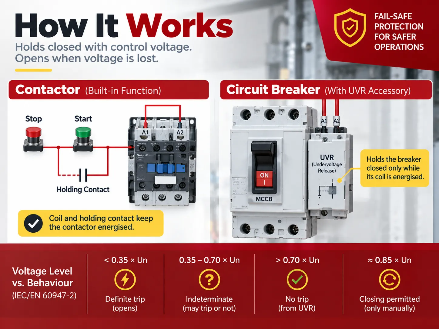
In its contactor configuration, the principle is very simple. The energy is supplied to the contactor coil by pressing the start switch, and when the main contacts close, an auxiliary, normally open contact in parallel to the start switch will close as well. This auxiliary contact, known as holding contact, continues energizing the coil after the operator releases the button. Therefore, even if it is released, the coil still has a path for the current, hence the circuit is maintained automatically as it does not require any external supply of energy to keep it in that state. Since it is the control voltage that actuates the device, we may say that the coil serves as the no-volt release. No additional component is required in the circuit.
With the circuit breaker, however, we find ourselves in a different situation, and thus most confusions arise. A circuit breaker relies on a mechanical latch, which means it stays in a closed position indefinitely without energizing the circuit. On the contrary, a safety mechanism, called the undervoltage release device in this case, has to be added as a solenoid with a latch that holds the mechanism closed only when its coil is energized. The specifications of such devices as per IEC/EN 60947-2 are the same with all major manufacturers:
| Control voltage (as a fraction of rated coil voltage) | Device behaviour |
|---|---|
| Below 0.35 × Un | Definite trip — the solenoid releases and the device opens |
| Between 0.35 and 0.70 × Un | Indeterminate — may trip, may not; this band is deliberately not a specification point |
| Above 0.70 × Un | No trip from the undervoltage function |
| Recovery to about 0.85 × Un | Closing is permitted again — but only by deliberate operation, never automatically |
From that table, two very practical take-aways can be made. The first is that the indeterminate 35-70% band means that a UVR cannot be counted on to trip at any one voltage level; it is a fail-safe device only, rather than being a precision monitor. The second item is that in the case of installations where there are brief written complaints about dips, a time delay unit is available; this unit will allow the trip to be delayed in the event of voltage sags for under about 200 milliseconds, allowing a brief voltage sag that does not affect the process to not bring the plant down. The selection of a time-delay UVR in cases where dips are common is the difference between providing useful protection and providing something operators will not use.
Two Forms: Contactor vs Breaker
Being able to understand which type of form you are using will prevent most specification mistakes since the two terms are distinct and do not serve the same purpose within a system.
| Contactor-based starter | Circuit breaker | |
|---|---|---|
| Holding mechanism | Electrically held coil plus auxiliary holding contact | Mechanical latch |
| What happens on supply loss | Coil de-energises, main contacts open automatically | Stays closed — the latch is not affected by supply loss |
| No-volt release provided by | The coil itself, at no extra cost | A separate undervoltage release accessory in the coil slot |
| Restart after outage | Impossible without pressing start again | Impossible only if a UVR is fitted; without one the breaker simply stays closed |
| Typical use | Motor starters: DOL, star-delta, soft starter, VFD contactor | Machine isolators, motor circuit breakers, ATS incoming breakers, feeder protection |
| Governing standard | IEC/EN 60947-4-1 | IEC/EN 60947-2 |
The example with the contactor pertains to why the term “no-volt release” is so common in British and Commonwealth standards; because every DOL starter comes with such a mechanism regardless of whether or not this specification has been made, thus giving us the acronym TONVR (thermal overload, no-volt release) as a description of the standard protection of a starter. The example with the breaker pertains to why the same specification can become costly; because if the upstream device utilized to protect equipment is a molded case circuit breaker rather than a contactor, the fail safe function must be purchased separately as an accessory. From these examples, rules of thumb may be derived; if the disconnecting device is a contactor, the function is free of charge, while if it is a breaker, the user must request access to the UVR part specifically and verify that there is an available slot in the frame for a coil.
UVR vs Shunt Trip
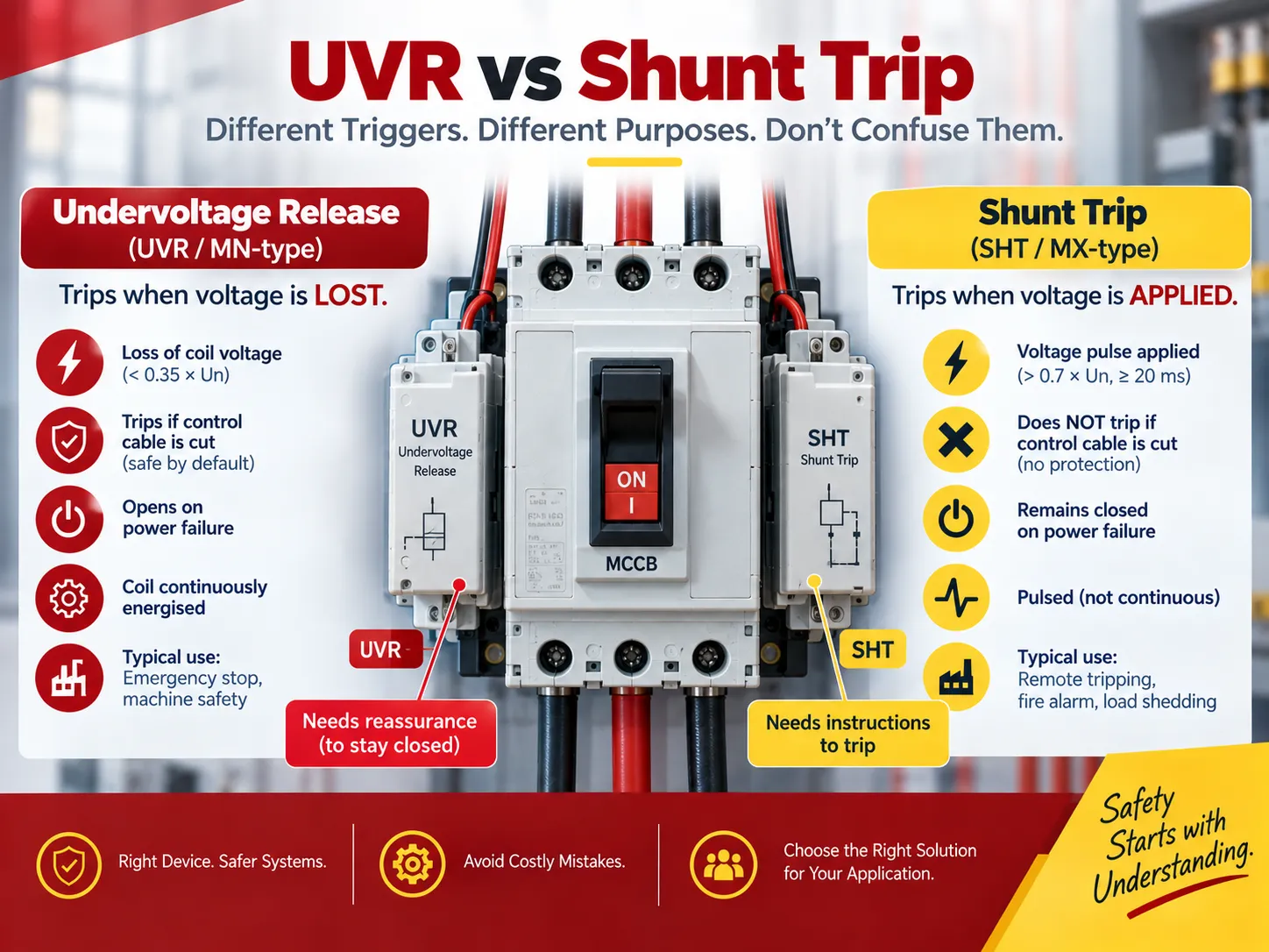
Despite looking similar and being mounted in the same location, shunt trip auxiliary and undervoltage release auxiliary are confused for one another on purchase orders quite often because they serve completely different functions. Mixing the two accessories is dangerous because shunt trip provides no protective mechanism whatsoever when it comes to a broken control wire.
| Undervoltage release (no-volt, UVR, MN-type) | Shunt trip (SHT, MX-type) | |
|---|---|---|
| Trigger | Loss of coil voltage, below 0.35 × Un | Application of voltage above 0.7 × Un, as a pulse of at least 20 ms |
| Behaviour if the control cable is cut | Device trips — safe by default | Nothing happens — the trip command never arrives |
| Behaviour on power failure | Device opens | Device remains closed |
| Reclosing | Permitted only above about 0.85 × Un, and only by deliberate action | Permitted whenever a command is issued |
| Coil must be continuously energised? | Yes — that is how it holds the device in | No — it is pulsed |
| Typical applications | Emergency stop circuits, unattended restart prevention, machine safety, source-healthy permissive on transfer schemes | Remote tripping from a protection relay, fire alarm interlock, load shedding, BMS-initiated disconnection |
An easy way to remember the difference between the two accessories is the fact that shunt trip requires a command while undervoltage release requires reassurance. In other words, shunt trip waits for a command to trip, but undervoltage release holds the device closed until power is lost; it opens immediately once power is cut. As previously mentioned, both provide an external trip mechanism that bypasses a panel’s internal thermal-magnetic or electronic trip device; however, only one fails safe.Where the objective is personnel safety, that difference is the whole point, and it is worth noting that a breaker’s overcurrent trip can be triggered by many conditions, which is a separate subject covered in our guide to what causes a circuit breaker to trip.
Where It Is Used
The applications are divided into those that necessitate safety and those that are process oriented and so equipment that utilizes safety requirements comes in to play effectively.
- Motor starters. DOL- or star-delta-type and soft-start and VFD-type motor starters utilize contactors held by the control circuit voltage. The no-volt feature protects an endless list of devices from unintended restarting.
- Machine tools and wood-working equipment. Saws, mills, presses, and drill presses provide an excellent illustration of the necessity for the device; it was designed to avert an undesirable restart while the machine operator changes the cutting tool or removes chips. Machine safety regulations also specify safety measures to avoid unwanted startups.
- Emergency-stop circuits. When the e-stop is wired as an interrupt in the coil circuit as opposed to being wired as PLC input, it becomes the fail-safe device. The PLC input could be misread, lose its power supply, or remain in a faulty module; a series contact in the control circuit will not.
- Hoists, elevators, and cranes. A lost power supply could ensure an uncontrolled restart and uncontrolled drop of the load.
- Unattended pumping and remote operations. Borehole pumps, irrigation pump stations, and remote booster pumping stations operate without an on-site operator. The last thing an operator wants is a pump that begins operating again in a dry line or blocked pipeline when power returns.
- Generator and automatic transfer operations. Under voltage relay will act as a permissive block closure until the incoming supply is in fact established.
- Interlocking fire alarm and building management systems. In the event of a fire, the fire control panel breaks the control voltage circuit.
- Load shedding. When a utility or site controller needs a circuit to open upon a supply condition, the control-voltage path provides a hardwired option.
It is important to note in the distribution equipment that the undervoltage release is an option among many which occupy the same pocket that is along with the auxiliary and alarm contacts, shunt trips, motor operators, and rotary manual operators. One specifications for the circuit breaker with UVR must ensure confirmation of the accessory stack before making an order and settled: whether the protection being fitted is a moulded-case breaker or a miniature device is a decision that affects which accessories even exist, as covered in our guide to the difference between MCCB and MCB.
Alternatives and Substitutes
Fail-safe function cannot be truly replaced, still, it can be imitated with various by-products of which each has its own risk.
| Approach | What it achieves | Trade-off |
|---|---|---|
| Contactor holding circuit (auxiliary NO contact across the start button) | The classic no-volt release — restart requires deliberate action | Only applies where the load is switched by a contactor, not by a breaker |
| Undervoltage release accessory on a breaker | Same fail-safe behaviour on mechanically latched devices | Extra cost, consumes a coil slot, needs a continuously energised control supply |
| Shunt trip plus relay or PLC logic | Can emulate restart-inhibit by programming | Fails unsafe: if the logic or its supply dies, the breaker stays closed. Not acceptable as a safety function |
| Motor protection relay with restart inhibit | Electronic restart blocking after a trip or supply loss, often with adjustable delay | Depends on the relay being powered and correctly configured; not a hardwired guarantee |
| Soft starter or VFD with undervoltage monitoring | Configurable restart behaviour, including inhibited restart | Same dependency on electronics; also adds a variable to commissioning |
| Mechanically latched contactor | Retains its last state across a supply loss | The opposite behaviour — it can restart unexpectedly. Used deliberately where auto-restart is wanted, never as a safety device |
| Local isolator with lock-off | Personnel protection during maintenance | Protects the maintainer, not the operator during an unattended outage |
There is a pattern to the contents of the table that deserves to be underlined: while physical solutions guarantee the reliability of the system, electrical systems do not. Indeed, a loss of Control Voltage cannot be misinterpreted, while a PLC input can be read incorrectly. This is why the fail-safe principle suggests that there should always be a hard-wire option for anything that protects human life, while all other operational features can be accomplished electronically.
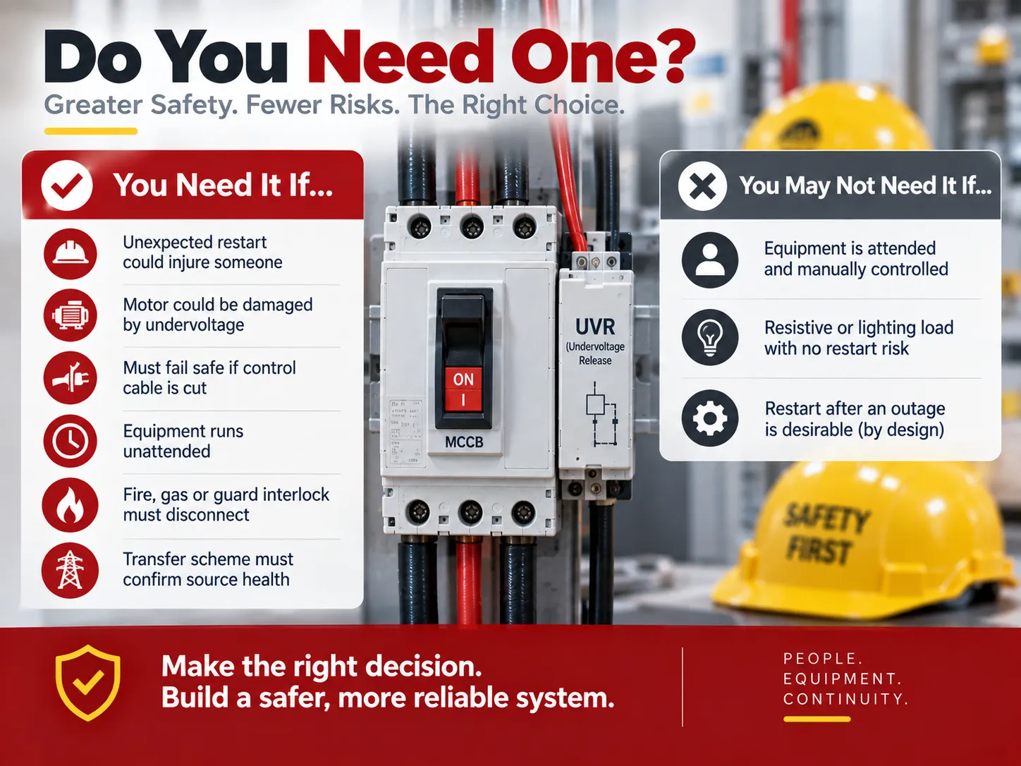
Do You Need One?
To put it quite frankly, the chances are that you have one on any motor that is controlled by a contactor. The real issue is whether the other devices that aren’t controlled by a contactor need one. It would be beneficial to make a short checklist.
You will need one if any of the following is true: there’s a possibility of shock from an unexpected restart; the load is a motor and there is a chance of damage as a result of sustained undervoltage; the system must shut down safely if the control cable is cut; the application is run unattended; there is a requirement to disconnect the load under certain conditions (fire or gas); or if the transfer scheme must confirm that the source is in good health before closing.
You might not need one if the equipment in question is attended and under local manual control; if the load is a resistive circuit or if there are no safety hazards associated with the circuit; or if an inconvenience associated with restarting the system after a shutdown is acceptable and the design uses a latching mechanism. In this last instance, the need for interlocks should be addressed in the design decision, rather than merely allowing the default behavior of the protection device to govern.
Specifying and Testing
Four specification points confirm whether the device works properly.
- Connect the coil to the control power, not to the line power. This is the most common mistake made in the field, which results in the most misleading symptom – a brand new undervoltage trip that is “not working”. The voltage rating of the coil is not the same as that of the power poles of the breaker, but the voltage rating of the control voltage that is generated by the panel such as 24 – 30 V DC, 110 – 130 V AC/DC, or 220 – 240 V AC/DC. Check the voltage rating of the coil on the control circuit diagram in order to avoid premature assumptions about mechanical problems, and realize that many of the accessories that are returned because they “don’t work” are really just ones with the wrong coil.
- Select the time delay version with care. For applications that experience voltage dips less than 200 ms followed by a resumption of the process that is being controlled, the time delay version is more than likely to provide unnecessary tripping. For these applications, the instantaneous version would provide better protection.
- Confirm that closing is being inhibited. The purpose of the accessory is to not only trip but to refuse to close the circuit until after voltage is restored to 85 % of its rated voltage or higher. Verification should be done at commissioning rather than relying upon assumptions.
- Put the coil on a periodic test schedule. Manufacturers recommend the routine testing of trip coils – usually at least every six months – because a failed coil will not be distinguishable from a functioning coil until it is needed.Testing a suspect device for electrical integrity uses the same techniques as diagnosing any other breaker fault, which our guide to how to tell if a breaker is bad covers in detail.
In cases where components are selected for a panel instead of being replaced in it, the protection layer should be specified as a package, including the breaker, associated accessories, and certified miniature devices installed on the same DIN rail.The HUM18-63N range is an example of the type of device that fills that role — a certified miniature circuit breaker line spanning 1P to 4P at 63 A with B, C, and D curves — and its HUM18-63N MCB product page shows the specification format buyers should expect to see documented.
Common Mistakes
- Ordering a shunt trip for use with a no-voltage release — both part numbers look similar and fit into the same terminal slots, but one method has a failsafe and the other does not.
- Hooking the coil to the line voltage. This guarantees either an burnt coil or a piece of equipment that stays open.
- Treating a mechanically-latched contactor as a failsafe. This design will actually keep its state, which is anything but what should happen.
- Making the emergency-stop function a purely software function on the PLC (no hard wiring). A software e-stop is not a failsafe e-stop; it is the hard wire break in the control circuit that guarantees the e-stop effect.
- Failing to implement the time-delay feature at a job site that is prone to fluctuations in voltage. The result is that your operation will experience nuisance shutdowns; once there are nuisance shutdowns occurring, the failover protection has been removed.
- Forgetting to include the accessory stack. A frame with one coil slot cannot house both a UVR and a shunt trip.
- Never performing a test on the coil itself. Failure is not visible UNTIL the time it becomes critical.
FAQ
What is the main function of a no-volt coil?
The purpose of the no volt coil is to maintain energy to the controlling device as long as the control voltage is being supplied. If there is a loss of control voltage the coil will open the circuit to prevent the resetting of the equipment from taking place automatically as the electricity is restored. The coil does this directly in a contactor starter by supplying the control voltage that holds the contactor in, but in other cases, a separate accessory for undervoltage release is provided to hold the mechanical latching mechanism. There is an additional function of providing protection for continuous undervoltage which could cause overheating and damage motors.
What is the difference between NC and NO contacts?
A normally open (NO) contact is open when at rest and will close when it is actuated, whereas a normally closed (NC) contact is closed when at rest and will open when it is actuated. The circuit creates a two-step operation of the contacts: the start pushbutton and holding contacts are NO so that pressing the button establishes the circuit; while the stop button, emergency stop, and overload relay contacts are NC to allow normal operation as long as they remain closed. NC contacts are utilized in safety circuits because they result in an “off” condition in the event of an equipment failure instead of a “permissive” action.
What is a no volt contact?
In a contactor starter, the no-volt contact is the auxiliary normally-open contact in parallel with the start push button, also known as the holding contact. The start button is pressed to energize the coil and the main contacts close. The auxiliary contact also closes and provides a path for the coil current to the device. This feature makes the circuit self-sustaining. The no-volt release works because the coil current depends on the control power through the contact. Therefore, if there is any loss of the control power, the coil loses power. If the holding contact is faulty, the motor can be started only when the button is pressed.
Does a DOL starter already include no-volt release?
Yes, all direct-on-line starters with electromagnetically held contactors include no-volt release. The acronym used for thermal overload protection with no-volt release is TONVR. There is no need to purchase any additional auxiliary. The device becomes an extra line item in the case of a mechanically latched circuit breaker.
Why is my undervoltage release tripping for no apparent reason?
There are a few reasons for the trip that occur usually in this situation. If a trip happens when other equipment starts, the installation should be updated to have a time-delay release. If the coil power is shared with other loads, the no-volt release may operate within the indeterminate band. The problem can be resolved by having an auxiliary power supply to the no-volt release.
References
- Schneider Electric — Undervoltage and Shunt Trip Release Technical Documentation
- ABB — Circuit Breaker Accessories: Undervoltage Releases
- International Electrotechnical Commission — IEC 60947-2 and IEC 60947-4-1
- EUR-Lex — Machinery Directive 2006/42/EC
- Health and Safety Executive — Guidance on Machinery Safety and Unexpected Start-Up
Conclusion
You may think the function of a no-volt release is quite extensive based only on its name, but this is not the case. Its high price is not an indication of the importance of the product either, since it does not properly check for voltage nor is it a general-purpose fall-back system. All it does is indicate when the control voltage is present so that it can be used as the initial condition for moving ahead when the voltage is safe and does not have to be checked. The no-volt release provides a great deal of benefit from this simple function. You will be able to restart following a power failure, disconnect during undervoltage conditions, use the no-volt release automatically in the event that the cable breaks and finally, prevent the circuit breaker from closing on no-load conditions. If you have a contactor starter, there is no additional cost for this no-volt relaunch system. If you have a circuit breaker, you will need to purchase it separately. Simply match the voltage of the coil and load, determine if there is a need for delay, and test the coil from time to time. As long as this approach is followed the consequences of having the no-volt release will be ensured, simulating what the safety system needs to provide.