
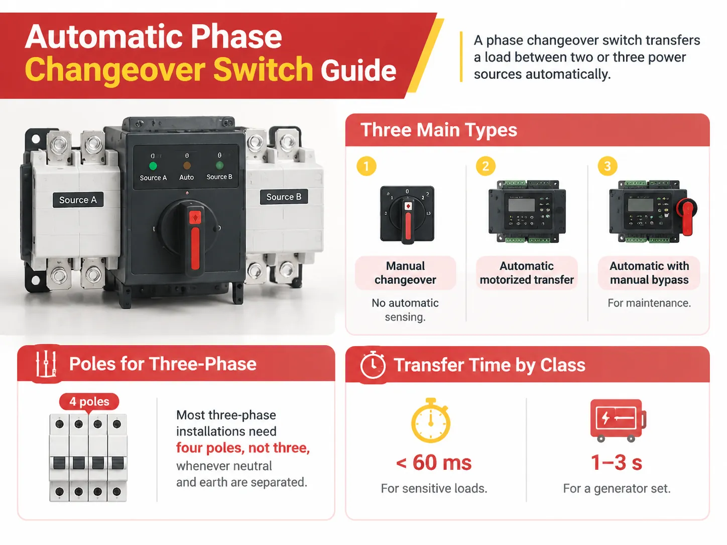
An Automated Phase Changeover Switch is a device that scans for power outages automatically and switches to the alternate power source without human intervention, ensuring that your electrical load remains operational even when active sources of supply fail. In addition to protecting your load, it will also allow the electrical load to maintain continuity during the short period of time (usually only seconds or fractions) needed to effect a switch over. One of the primary misconceptions among customers about the Automatic phase changeover Switch is the amount of time it will take to implement the phase transfer. However, the other variable customers must be concerned with is the number of poles in the unit; this will directly impact the safety and cost of the system, as well as the installation and maintenance requirements for the Electrician.
A phase change switch is an automatically-switched device that switches (or transfers) current from one source (input) to a different source (output) among two or more sources. Phase-change switches are available as manual, motor operated, or automatic, and the automatic type can include an easy-to-operate manual bypass for maintenance and repair procedures. When considering three-phase configurations, each phase requires four poles; one for each phase and a separate neutral/ground pole. The transfer time of the switch will determine if it is classified as a type: depending on the sensitivity of the equipment being connected, it will generally have a transfer time of less than 60 microseconds for sensitive devices and a transfer time of approximately between 1 second to 3 seconds for generators.
What the device actually does
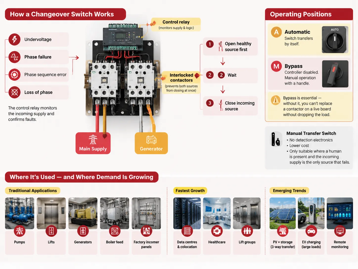
There are two components inside a changeover switch that are overlooked by people: 1, a control relay that monitors and watches out for faults in the incoming supply., and 2, a pair of interlocked contactors which allow for a physical transfer to take place i.e. opening and closing of the contactors. The control component looks out for defects in the incoming supply such as undervoltage, loss of phase, phase failure and phase sequence errors. As soon as a fault is detected, the controller logic ensures that the contactor associated with the good power supply is first opened and after that the contactor of the incoming supply is closed. The interlocked nature of the contactors ensures that both supplies are never connected at any given time.
There are two configurations in which a changeover switch usually operates. The automatic configuration is the normal operation mode whereby the switch itself does the transfer or changeover. The bypass mode is a maintenance mode in which the controller is put out of action and a technician uses a maintenance handle to operate the switch. Bypass is, however, a highly important mode of operation; without it, the technician would have to put the entire supply down just to change a contactor on a live switchboard.
One older alternative that keeps appearing in specifications is the manual transfer switch: same hardware, no detection electronics. It is cheaper, and it is the right answer when the incoming supply is the only source that ever fails and a human is standing there. It is the wrong answer for a lift or a server room.
Where changeover switches get used, and where the demand is going
The existing technology is dated and unexciting: pumps, lifts, generators, boiler feeds and factory input units. These systems are reliable. In fact, growth in the sector comes from other sources.
Currently data centers and colocation take the leading position as the single-phase transfer of just a few milliseconds saves the rack from shutting down during a power loss, instead of using a battery pack large enough for all possible incidents upstream. Healthcare comes in second, because keeping the supply uninterrupted is a requirement rather than an option in critical care areas. Lifts are in third position when movements are likely to be taken over by the new technology, when one controller will be controlling a lift group.
Legal issues and some smaller trends need to be addressed. Customer buildings are incorporating PV and battery systems, using a three-way transfer instead of just two-way options. Large electric vehicles are causing huge power consumption that the grid cannot always manage resulting in connecting to the power source instead of constantly switching it on.
Roughly speaking, three-phase versus single-phase is not a preference you get to have once the load is over about 7 kW, and the distinction is covered in single-phase against three-phase explained.
Types and classes
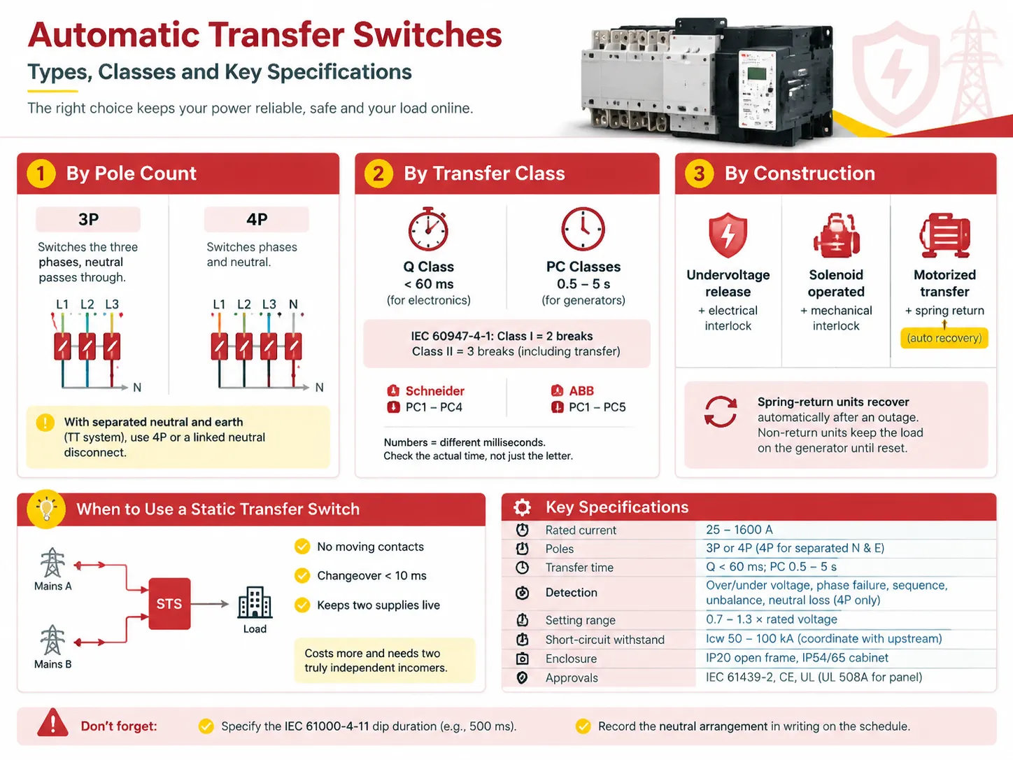
It is important to learn the databook shorthand for the three principles of three-phase changeover switches.
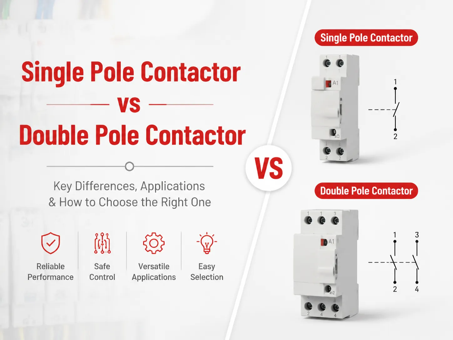
In the first dimension – the number of poles, a 3-pole switch turns off the three phases while keeping the neutral connected along the way. A 4-pole switch turns off the neutral as well. When the neutral and earth are separate, for example in a TT system, keeping the neutral connected defeats the purpose of having them separated — the neutral is still connected to the earth electrode. Using a 4-pole switch or switch with linked neutral disconnection is the way to go when it comes to most setups outside the USA.
The technology dimension is related to the speed of switching. Vendors use this terminology in a different way. According to the IEC 60947-4-1 standard, there are classes I (two breaks and transfer) and class II (three breaks including transfer). Class Q means that the transfer takes ten milliseconds at the longest and should be used in the case of electronic devices. Schneider and ABB have different sets of class values taking into account the transferring time.
The construction dimension is about the key characteristics of the mechanism – undervoltage release with electrical interlocking, solenoid type with mechanical interlocking, or spring return motorized type, which is the only switching technology that brings the mechanism to mains automatically in the event of an outage. This is important in a lot of situations that are not always clear: spring-return mechanism goes back to normal operation, while the other types keep your load on the generator until someone comes to turn it off.
When the switch only transfers electricity between mains A and mains B, and both power sources are always available, a static switch is the best solution, as it has no moving parts and transfers in less than 10 ms keeping both supplies working. However, this option is more expensive and requires two separate connections to work properly.
The specifications that decide the purchase
| Parameter | What buyers specify | Notes |
|---|---|---|
| Rated current | 25, 32, 40, 63, 80, 100, 125, 160, 250, 400, 630, 800, 1000, 1250, 1600 A | Size to the full load current, then check the starting current if motors are on the bus |
| Poles | 3P or 4P | 4P wherever neutral and earth are separated |
| Transfer time | Q class under 60 ms; PC classes 0.5–5 s | Generators need seconds, electronics need milliseconds |
| Detection | Under/overvoltage, phase failure, phase sequence, phase unbalance, neutral loss | Neutral loss detection only exists on 4-pole units |
| Setting range | Typically 0.7–1.3 times rated voltage | The tolerance matters more on a weak supply |
| Short-circuit withstand | Icw, typically 50–100 kA depending on frame | Must be coordinated with the upstream breaker |
| Enclosure | IP20 open frame, IP54/65 cabinet | Bench-mount needs a cabinet in a plant room |
| Approvals | IEC 61439-2, CE, and UL where the site is North American | UL 508A applies to the panel, not the switch alone |
Short-circuit withstand is the specification people argue about last, and it is where the relationship with the breakers around the switch becomes concrete: the withstand has to be coordinated with the upstream device, and the terminology for the rest of that panel is covered in how the switch relates to the breakers around it. Two additional pieces of information should be left until the commissioning engineer is present. First, specify the IEC 61000-4-11 dip duration you are protecting against; a switch that reports recovery in 200 ms will not be able to bridge a 500 ms sag. Second, clearly state in writing the arrangement of the neutrals on the schedule.
Advantages and disadvantages
| Advantages | Disadvantages |
|---|---|
| No interruption to the load beyond the declared transfer time, unattended | It is a mechanical device with a finite number of transfers, typically 50,000 to 100,000 operations |
| Interlocked, so the two supplies cannot be closed together | Mechanism wear is invisible until it fails, and then the load drops |
| Spring-return versions recover without anyone attending | Non-return versions need a manual reset after every outage |
| Detects phase failure and sequence errors that a simple fuse arrangement would miss | 4-pole versions cost more and need a neutral to be brought to the switch |
| Remote status reporting is available on most modern controllers | Remote reporting needs a supply and a communications route; on an isolated site it is a cost with no payback |
| A manual bypass allows maintenance without dropping the load | Bypass in manual position is a state an operator can forget to leave, which is a real risk in a plant room |
Before reading a firsthand account, one should always check out the second column. Its importance lies in two things: the transfer switch guards you against loss of supply but not against failure of the system itself through wearing out; wearing out translates into the switch having to be operated manually, whether you like it or not.
Brands, and what they cost
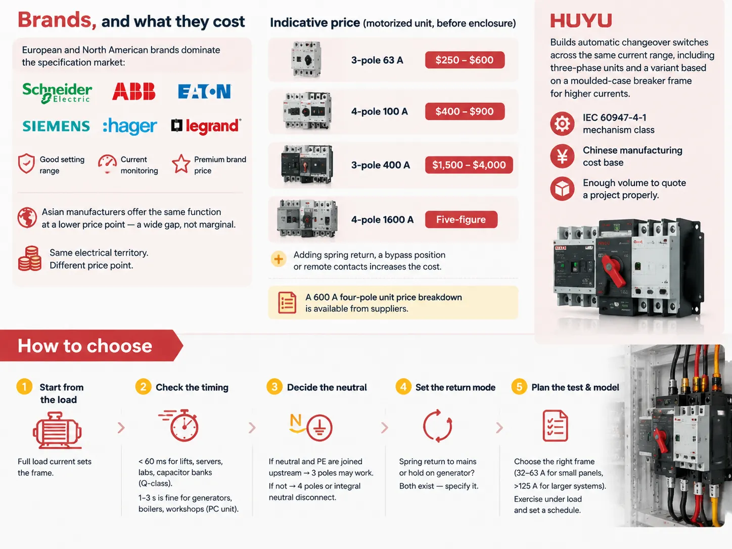
North American and European operators are the main ones occupying the specification market: Schneider Electric has introduced its Prisma and Compact ranges and NGOs like ABB, Eaton, Siemens, Hager and Legrand operate at the same level. They have considerable control range, current monitoring capabilities in their controllers, and install all of that for customer charges that do not include brand attributes.
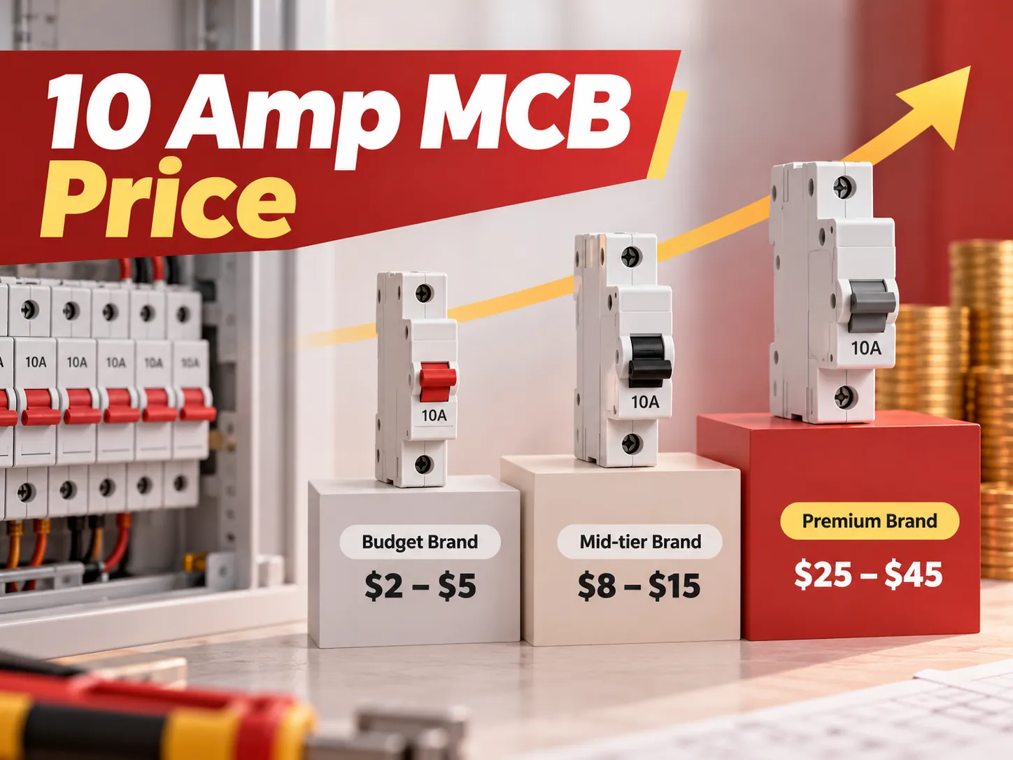
Asian manufacturers are working in the same field, but their prices are lower. The gap is not insignificant, as illustrated by the following quotes for a motorized device without housing with over/undervoltage detection.
The price for three poles with 63 Amps capacity is from $250 to $600. The price for four poles with 100 Amps is between $400 and $900, and the price for devices with 400 Amps is $1,500–4,000. As for devices with 4-poled design and capacity of 1600 Amps, they will cost more than $10,000. Adding spring return, bypass position or remote contacts will make the price for the device higher.Independent of supplier, the cost of one unit at 600 A is set out in the 600 A four-pole price breakdown.
The company HUYU produces automatic transfer switches that cover the same current range, with three-phase devices and circuits built on a molded case circuit breaker cover frame for larger currents. The business model is simple: all units are based on the same IEC 60947-4-1 mechanism class, produced according to Chinese prices, and the volume is enough for proper victory in the project quotation.
How to choose
Commence with the load rather than the switch. Full load current establishes the frame; the presence of any motors on the bus determines whether a greater short circuit withstand is required than what the data sheet indicates.
Then there is the timing. If the load consists of a lift controller, a server, laboratory test bench or anything with capacitor banks, the transfer must be done in less than 60 milliseconds and a Q-type device will have to be specified. If it is a generator set, a boiler feed pump, or some sort of workshop, one-second delays are acceptable and a less sophisticated spring return type of device being easier to use.
Lastly, the neutral must be discussed. Determine whether the neutral and the protective earth is joined at some point upgraded. If yes, then one can use three pole devices. If no, four-pole devices or a neutral disconnection device will be the right solution, and that makes more impact than any feature in the features list.
What will happen on the way back also needs to be determined. A spring return to the grid or a hold of generator unit until instructed to switch off. Both options exist and need to be specified specifically, as default might not correspond to what you need.
Finally, decide how much you will test, and ask for the model number early. A compact frame such as the automatic changeover switch in the 32 to 63 A band covers small panels and small generators; above about 125 A you are into a different frame family with different short-circuit ratings, and the datasheet has to match the panel. A changeover switch needs to be operated under load when it is commissioned and then regularly. The interval of operation is far more critical than any monitoring feature of the switch and is often the missing item in the maintenance schedule, thereby causing the mechanism to reach its limit without being noticed.
FAQ
What does an automatic changeover switch do?
The device is able to monitor a single power source, determining when the source has gone out of range or failed, allowing for the transfer of the load to another power source automatically. The transfer is interlocked, which eliminates the possibility of connecting the two power sources. Also, in most units, it is able to detect the occurrence of phase failure, phase sequence error and in some cases, a loss of neutral in four pole machines.
What is the best automatic changeover switch for a home?
An automatic changeover switch is seldom the answer for homes. Most single-phase residences don’t have a backup supply to switch to, and where one exists, an interlocked changeover for one or two key circuits is sufficient. The genuine domestic scenario is where there is a generator in place where a changeover for the heating, refrigeration, lighting, and one socket circuit solves all the problems for a lot less than a full-on automatic system.
What does automatic changeover do?
The load is transferred instantly from one source to another once detected, and mostly transferred back again automatically. The key term here is automatic; although manual switching looks almost the same from outside, it requires human intervention. The automatic switching equipment is the type used in the situations where continuity of load needs to remain in operation without any attendance such as elevators, fire alarm systems, data centers, water pumps, and critical circuits in hospitals.
How do you connect an automatic changeover switch?
Two incoming connections land on two supply terminals, load connects to common connectors and control connection connects to control terminals. One must decide if neutral has to connect on a 3 pole or a 4 pole unit before pulling the cable. Connection is done using terminals or lugs specified by the manufacturer, and torque is given at the prescribed value while verifying the rated transfer time while connected.
References
- Schneider Electric — automatic transfer switch ranges and transfer-class terminology
- ABB — low-voltage switchgear including automatic transfer switches
- Hager — changeover and transfer switch product families
- Legrand — switchgear and distribution board solutions
- Eaton — IEC 61439 low-voltage assemblies and North American switchgear
- International Electrotechnical Commission — IEC 60947-4-1 (transfer switches), IEC 61439 (assemblies), IEC 61000-4-11 (voltage dips)
Conclusion
If you ignore technical considerations for an automatic phase changeover switch, it is easy to understand the operation of its switch. There are essentially two points you must consider regarding the switching mechanism: the speed at which the changeover occurs and the number of poles involved in the switching operation. Once you have confirmed that the switch has the correct pole number and changeover speed, it will be much easier to understand how the rest of the switch works. However, if you confirm a switch has the wrong pole number, it will pass the torque test but fail the safety test which can be a much higher expense.