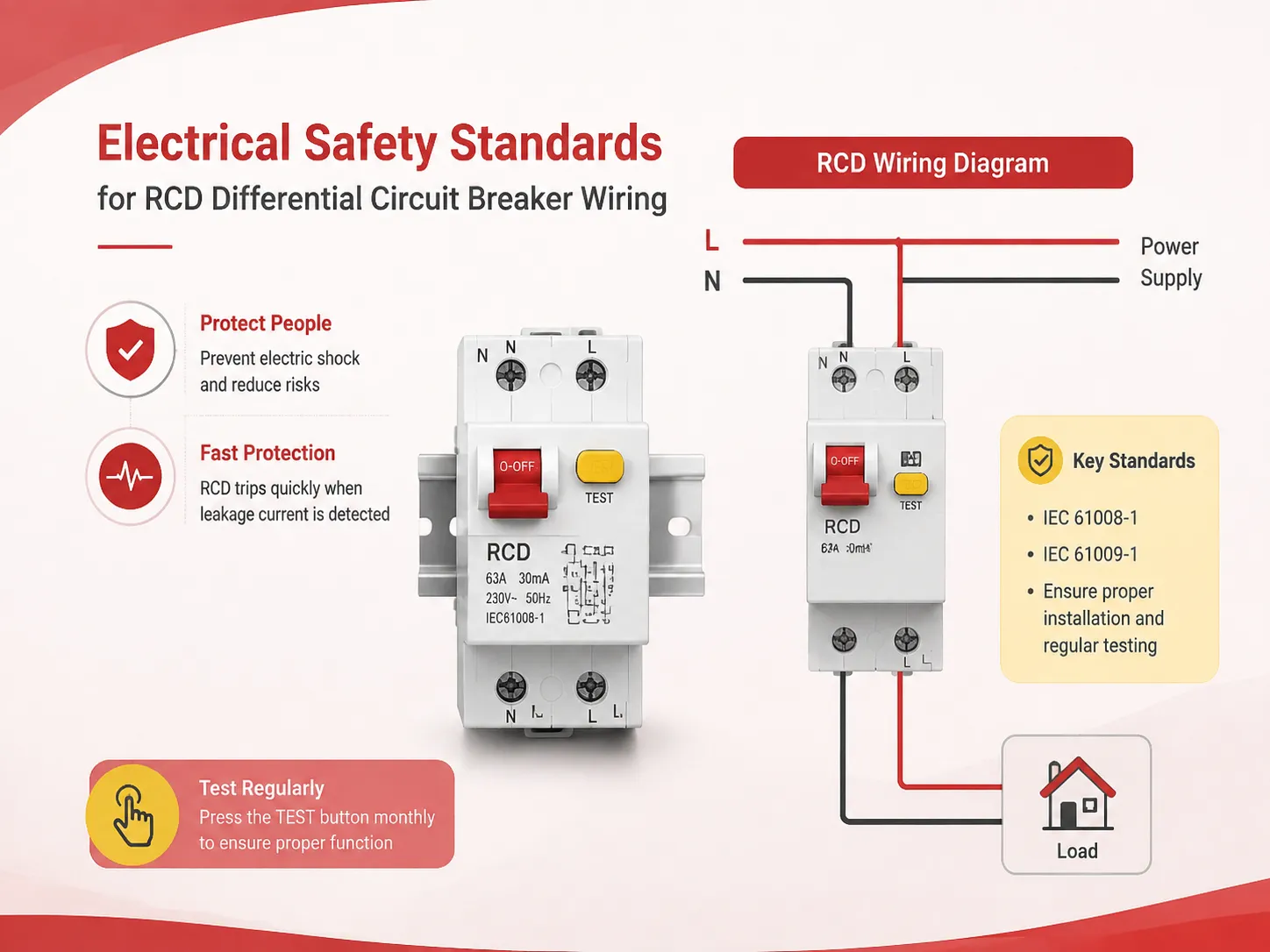
A residential consumer unit was installed by an electrician in Manchester who connected it in exactly the same way as the previous installation. The wiring appeared neatly done, the screws were tight, and the connections performed well after first power up. However, after about six months a problem did surface in the immersion heater circuit and caused a trip in the chain both on the RCD protecting the circuit, and also on the upstream RCD system causing a blackout in the house. In the dark, the homeowner fell on the stairs and broke their arm. The investigation showed that a mistake was made by the electrician in connecting the neutral wires in the circuit. The neutral provided for one circuit was connected into a wrong neutral bar, leading to the RCDs functioning simultaneously after about six months of no issues. The mistake was impossible to identify through a simple socket testing since it had happened at a fault moment. The lesson that follows from that is quite simple: the installation of RCDs is not just about connecting the wiring properly. It is all about adequate knowledge of certain pathways, segregation of neutral conductors, earthing and testing requirements. This guide provides the major rules of wiring, basic schemes and simple steps allowing for successful and safe installation of the RCD.
Summary: The wiring techniques of RCD are regulated by national and international regulations—IEC 60364, BS 7671 (The IET Wiring Regulations), NEC in North America—and they include the following cornerstones: For every protected circuit, the live and the neutral must go through the RCD (in case of RCBO) or be connected to the side protected by an RCD in the distribution board (in case of shared RCCB); the neutral of different RCDs must not be mixed; the protective earth must never go through the toroidal coil of the RCD; the RCD must be installed after the main switch and the overcurrent-protecting devices; and last but not least, testing must be done for every installation to verify that the RCD works as expected when the rated residual current is applied.
RCD, RCCB, RCBO, GFCI: Understanding the Terminology Before You Wire
It is important to clarify terminology before discussing the wiring standards, as terms and definitions differ from place to place and by the particular device type, and so do wiring requirements. An RCD (Residual Current Device) denotes the general term for any device that calculates earth leakage current and disconnects the circuit. In the UK and IEC market, it is most commonly the RCCB (Residual Current Circuit Breaker), which only disconnects the circuit upon detecting the earth leakage, therefore requiring a separate MCB for providing protection against overloads and short-circuits, as well as the RCBO (Residual Current Breaker with Overcurrent), which combines earth leakage, overloads, and short-circuits protection into one device. In North America, the name used for the similar device is GFCI (Ground Fault Circuit Interrupter) and it is often used just as a receptacle outlet instead of the standard DIN rail device, but it is also available as an additional circuit breaker.
The phrase “differential circuit breaker” is also common in some European and Latin American markets but refers to the RCBO, the device that disconnects the circuit upon the detection of the differential between the current in the live and neutral wires. Therefore, the term RCD is to be used meaning the general name for residual current devices, while the differences in wiring requirements for RCCB, RCBO, and GFCI application are to be stated. For a detailed comparison of RCCBs and RCBOs—what each one does, how they differ, and when to use each—our article on the difference between RCCB and RCBO provides the complete technical background. And for the broader context of the earthing systems that determine how an RCD functions, our guide on power supply systems explained covers the TN‑S, TN‑C‑S, TT, and IT arrangements that define where and how an RCD must be installed.
The Fundamental Wiring Rules: What Every RCD Installation Must Satisfy
The wiring of an RCD is governed by a small set of absolute rules, each of which is derived from the physics of how the device works. Violating any one of them will prevent the RCD from operating correctly under fault conditions, and the violation may go undetected until a fault occurs. The rules are as follows, and they apply to every RCD installation, regardless of the device type, the earthing system, or the country.
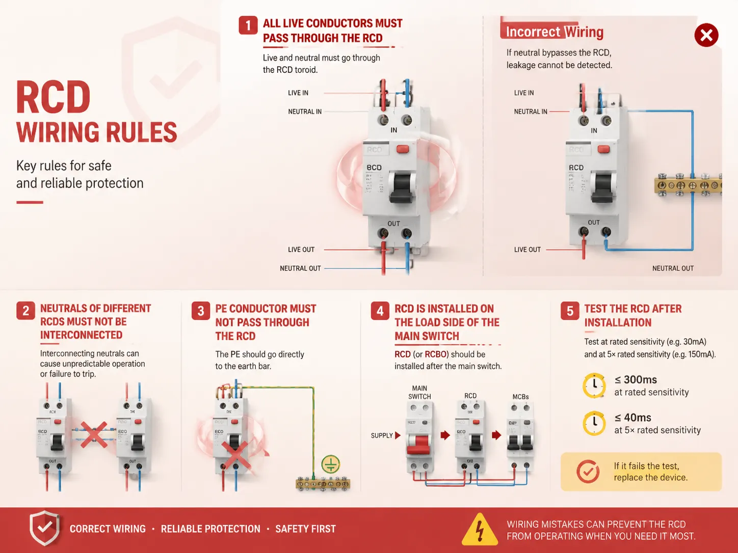
- First of all, all the conductors of the live parts in the protected circuit must pass through the toroid of the RCD. In the case of a single-phase RCBO, both live and neutral go through the internal toroid of the RCD, where the live is connected to the input terminal of the RCBO, subsequently going through toroidal coil and the overcurrent protection devices before reaching the output terminal. The neutral is connected to the neutral input terminal, passes through the toroid, and exits through the neutral output terminal. In case the neutral is connected to the unprotected neutral bar and not to the neutral terminal of the RCBO, there will be a difference between the current on the live side and the current on the neutral side of the device, whereby the amount of leakage flux detected by the RCD will be equal to the current at the load, regardless of the load intensity.
- The neutral conductors on different RCDs should not be interconnected or interlinked. The action of the Manchester electrician where the neutral from one RCD’s circuits joined to that of another RCD’s neutral bar is one of the usual cases of RCD wiring mistakes. When two RCDs are connected through the same neutral, the circulating currents of the two circuits may split randomly between their toroids, allowing the equipment to work normally in the process. Only in abnormal conditions, the two RCDs may trip together or not trip at all. The operation of the two RCDs is complex and cannot be predicted using any existing means.
- The PE (protective earth) conductor should not be passed through the toroid of RCD. This is due to the fact that RCD works on the concept of live and neutral current’s imbalance. The earth conductor generally does not carry any current except in the case of a fault. So, if the earth conductor were to go through toroid, any earth leakage current that RCD is supposed to identify will be negated because current in the earth wire will be balanced with the same current going back through the earth conductor. When this happens, since both current flow through the same toroid, the RCD will detect zero imbalance and as a result will not trip. The earth conductor is wired to the earth bar in the distribution board, and thus skips the RCD altogether.
- Installation of the RCD occurs on the load side of the main switch. An RCCB is connected to the main switch. It is then connected to the MCBs which protect the particular circuits. An RCBO serves as an overcurrent protective device while connecting to the main bus bar at the line side. The RCD cannot be installed on the supply side of the main switch: otherwise, the user will not be able to isolate the device when having an issue.
- Testing of the RCD is a must after installation of wiring. It is necessary. The standards‐BS 7671, IEC 60364 and NEC all require that the RCD must be checked at commissioning stage to ensure that it trips quickly in a stipulated time for the residual current. The test process is done by using the RCD tester which is a tool that can also measure the time of trip. The test is performed at the rated sensitivity of the RCD which is usually 30mA and then at five times of rated sensitivity that is 150mA. The trip times should not exceed 300ms at rated sensitivity or 40 m at five times rated sensitivity. If the device fails to meet the time limit then it must be replaced.
Step‑by‑Step: Wiring a Single‑Phase RCBO in a Distribution Board
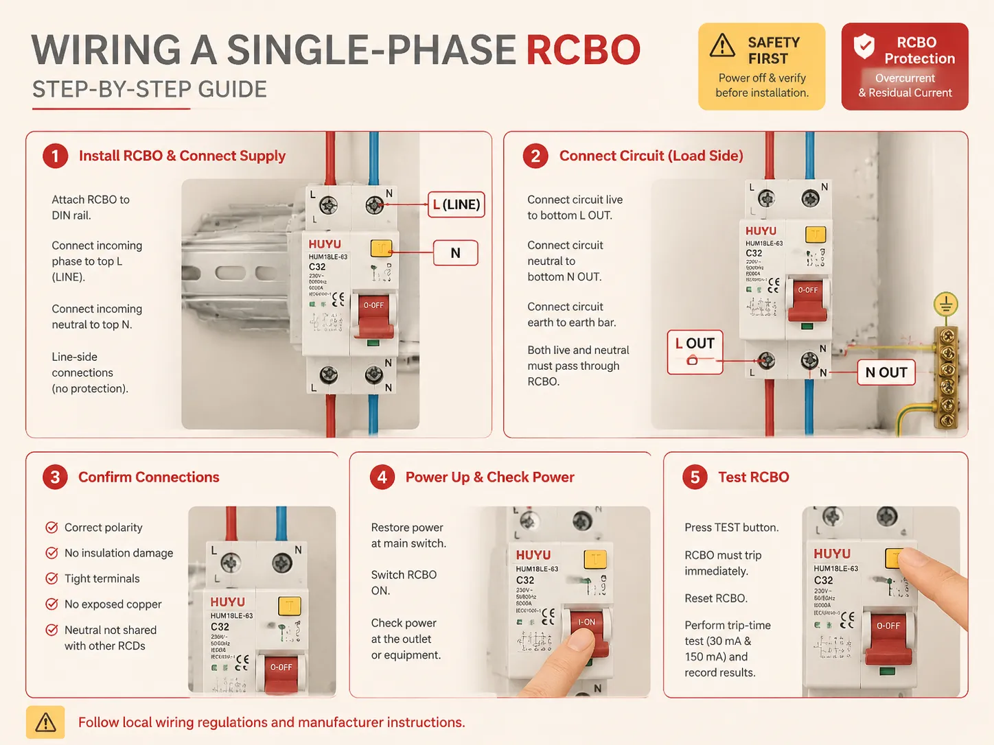
The following procedure describes the wiring of a single‑phase RCBO in a residential or light commercial distribution board, using a DIN‑rail device such as HUYU’s HUM18LE‑63 RCBO. The procedure assumes that the distribution board is correctly installed, that the main switch is off and locked out, and that all conductors have been verified dead before work begins.
- Install the RCBO onto the DIN rail and connect the supply. Attach the RCBO to the DIN rail properly. Connect the incoming phase (from the main switch or bus bar) to the top phase terminal of the RCBO, which is usually labeled “L” or “LINE.” Connect the incoming neutral (from the main neutral bar) to the top neutral terminal of the RCBO, commonly labeled as “N.” These are the line-side connections, which do not receive protection from overcurrent and residual current protection. Tighten the terminals to the required torque indicated on the device body.
- Connect the circuit as follows. The live conductor of the circuit is wired to the bottom live terminal of the RCBO, which may be labeled “LOAD” or “L OUT.” The neutral color of the circuit is routed to the bottom neutral terminal of the RCBO, which may be labeled “N OUT.” It is important that both the live and neutral wires of the circuit connect to the RCBO. The ground wire of the circuit is connected to the earth bar in the distribution board, but it does not connect to the RCBO.
- Confirm the connections. Make sure that the live and neutral conductors are correctly identified, that there is no damage or pinching of the insulation, that the terminal screws are firm, and that there is no bare copper outside of the terminals. Make sure that there is no connection between the neutral in the circuit and either the other nneutral bar or any other RCD’s neutral circuit.
- Power up and check functionality, restore power at the main switch. Switch the RCBO in the ON position. Check if power is available from the socket tester or measuring voltage on the connected equipment. Press the TEST button on the RCBO. The device must trip immediately and power should be lost. Reset the RCBO. Make a calibrated trip-time test with RCD tester at the end of the connected circuit and keep track of trip time at 30 mA and 150 mA. The test results should meet the requirements from wiring regulations.
Wiring an RCCB Protecting Multiple Circuits: The Neutral Bar Rule
Whenever just one RCCB takes control of many circuits—such as when several MCBs use just one RCCB for their power up supply—the wiring procedure that must be adhered to accurately is known as the neutral bar rule. The output neutral from the RCCB is connected to a unique neutral bar, which only powers the circuits protected by the RCCB. Every circuit protected by the RCCB has to use the neutral from that bar. However, every circuit not being protected by the RCCB has to use the main neutral bar, which is on the unprotected side of the RCCB. The two neutral bars are not merely different from one another; they are completely separate and electrically isolated from each other. The instant one of the neutral wires from an unprotected circuit is accidentally connected to the protected neutral bar, the RCCB instantly senses the different currents flowing in the live wire (not passing through the RCCB) and the neutral wire (which is passing through the RCCB) and trips immediately. Moreover, in case the neutral from one of the RCCB’s circuits is connected to another RCCB’s neutral bar, it may not give out an alarm as such, but will do so in case of earth fault situations. The neutral bar rule is the most important wiring principle in a distribution board with multiple RCDs and the one which is regularly broken. For help identifying the correct device for any circuit, our guide on what size circuit breaker you need explains the NEC‑based sizing process.
Special Considerations for Type B, Type F, and DC‑Sensitive RCDs
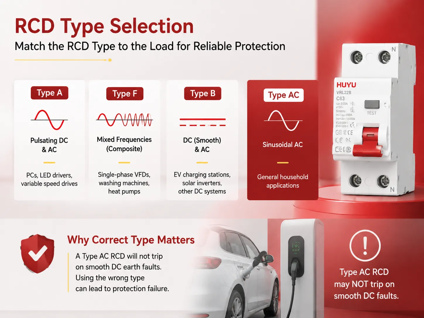
Not every type of RCD will operate in response to all residual currents, so employing an incorrect RCD for any connected equipment can lead to a failure of protection. The most prevalent type of RCD is Type AC, which detects sinusoidal AC residual currents, similar to those that would be caused by a human being in contact with a live wire. Although they work well for most domestic applications, Type AC RCDs have been widely superseded by Type A RCDs, which also operate with pulsating DC currents from appliances that include rectifiers, such as PCs, LED drivers, and variable speed drives. Moving to the next level, Type F RCDs provide protection against composite residual currents with a combination of frequencies and they find their application in circuits operating with single-phase VFDs and certain types of washing machines and heat pumps. Finally, Type B RCDs operate with both pure DC and AC residual currents and find application in EV charging and solar inverter circuits. HUYU manufactures Type B RCDs, including the VRL22B Type B RCBO, for these applications. The wiring of a Type B or Type F RCD follows the same rules as for any other RCD—the live and the neutral both pass through the device, the neutrals of different RCDs are segregated, and the earth does not pass through the toroid—but the selection of the correct type for the load is a safety requirement, not a preference. An EV charger protected by a Type AC RCD will not trip on a smooth DC earth fault, because the Type AC toroid cannot detect it. The RCD will appear to function—the TEST button will trip it—but it will provide no protection against the specific type of fault that the connected equipment can produce. The Institution of Engineering and Technology (IET) provides guidance on the selection of RCD types in its Wiring Matters publication, and the relevant product standards are defined in IEC 61008 and IEC 61009.
Frequently Asked Questions
What is a RCD breaker used for?
An RCD (Residual Current Device) circuit breaker is designed to provide protection against electric shock by identifying electricity leakage—for instance, electric current flowing along the body of a person or through a faulty connection—and shutting down the circuit within a few seconds. Electric regulations stipulate that RCDs should be installed in almost all homes and businesses in circuits serving bathrooms, kitchens, outside territories, and other potentially dangerous places.
Is an RCD a GFCI?
Indeed, there is no difference between RCD and GFCI (which is an abbreviation of Ground Fault Circuit Interrupter). The phrase “RCD” is applied in UK, Europe, and IEC markets while “GFCI” is used in North America. Both devices indicated by these terms, experience the imbalance of the live and neutral currents and interrupt their work if the difference reaches 5mA (this corresponds to North America) or 30mA (this corresponds to IEC markets).
Where should RCDs be installed?
Installing residual current devices (RCDs) on final circuits servicing bathrooms, electrical equipment outdoors and socket outlet circuits is mandatory as per electrical safety regulations. BS 7671 law dictates that RCDs with an operating value of 30 mA must be fitted on almost all socket outlet systems in domestic installations in the UK, any circuits with baths/showers and with cables installed in walls less than 50 mm away from the surface, which do not have earthing protection of any kind. However, depending on one’s country of residence and to which edition of wiring regulations one adheres to, requirements regarding RCD usage will vary, hence checking the local codes is always advisable.
What is a differential breaker?
The differential circuit breaker is a name used for the RCBO in some Latin American and European markets, the device providing combined residual current (earth leakage) protection, plus overcurrent (overload and short-circuit) protection. The term “differential” expresses the principle of operation of RCBO: the device detects the difference “differential” in the current flowing in the live conductor and the current flowing in the neutral conductor and trips if the difference exceeds the maximum allowable value of the residual current. The differential circuit breakers produced by HUYU are suitable for AC, DC, and mixed frequency applications, providing all the necessary certifications.
References
- IET — BS 7671 Requirements for Electrical Installations (IET Wiring Regulations). The UK national standard governing the installation of RCDs, including the types, the wiring requirements, and the testing procedures.
- IEC 61008 and IEC 61009 — Residual Current Devices. The international standards that define the construction, testing, and performance of RCCBs (IEC 61008) and RCBOs (IEC 61009).
- NFPA 70 — National Electrical Code (NEC) — GFCI Requirements. The North American standard for GFCI installation, including the locations where GFCI protection is required and the wiring rules that apply.
- Hager — RCD and RCBO Wiring and Application Guides. Manufacturer of distribution boards and protective devices, with technical guidance on RCD wiring, neutral bar segregation, and trip‑time testing.
Electrical safety standards for RCD differential circuit breaker wiring are not suggestions. They are the rules that ensure that a device designed to protect a life will actually do so when a fault occurs. All of the rules surrounding wiring that electricity employees follow when installing an RCD stem from the fundamental belief of balance in electrical current. If any of these rules are violated, it will mean the RCD fails to protect a person as it should. An electrician who wires the neutral incorrectly, who connects an earth wire through a toroid or who does not conduct a tripping time test will never know about the faulty installation—until a fault develops and the RCD cannot trip as it should. HUYU manufactures all kinds of RCDs and other devices according to guidelines that say the device stopping a person from experiencing electric shock should be correctly wired, tested, and completely reliable the very moment it is put into practice.