A recent incident involved a contractor in Illinois who ran cables for a new commercial kitchen by using 10-gauge copper THHN for a 30-amp, three-phase, 208-volt circuit for a convection oven. This type of conductor is rated for 600 volts. The NEC ampacity chart approved 35 amps for use with this conductor in the specific installation. It seemed that everything was in order, but the inspector disapproved the installation not due to wire size or voltage rating, but because the contractor ran the 208-volt wire within the same raceway as several 120-volt branch lighting circuits without any physical barrier. This violates the NEC requirement saying that wires of different voltage classes should be separated unless all of them are insulated for the maximum voltage. To make the installation compliant, it would be necessary to take out the wires with the higher voltages and instead use a separate conduit for them. The main conclusion is classical — meeting the NEC requirements in terms of wiring and voltage doesn’t mean just seeing the ampacity and insulation rating. There is an interplay of voltage, insulation rating, distance, and safety gaps. This guide describes the basic NEC rules which connect wire dimension and insulation.
Summary: The NEC contains nothing like a chart that specifies which wire is to be used for each voltage level. What the NEC does present instead is a complex array of interrelated specifications that describe several important factors affecting the relationship between a wire and the voltage carried by it. Among such key specifications, we find insulation voltage rating (NEC Article 310.4—requires that all wires are insulated adequately for the highest voltage that can appear in the raceway or cable and that wires of different voltage class are separated from one another unless properly insulated), ampacity and temperature rating (NEC Article 310.16 and relevant tables—determines the capacity of wires based on wire gauge, insulation temperature rating, ambient temperature and the number of wires in the raceway and requires that wires’ gauge is calculated as to provide wires flow capacity no less than that of the load current and circuit breaker rating), voltage drop (NEC Article 210.19(A) Eng. Note No. 4 requires that no more than 5% voltage drop should occur during the wire operation on any branch circuit and not more than 3% in the feeder and 2% in the conductor) and the 125% adoption principle (NEC Article 210.19(A)(1)—states that gauge of the wire should correspond to 125% of the continuous load plus 100% of the load intended for use in a non-continuous operation). All of the aforementioned specifications are interrelated: for example, a wire that is compliant with insulation standard can happen to be smaller than required for ampacity and/or voltage drop; likewise, a wire that conforms to sizing standards may turn out to be wrongly installed in case it is placed in the raceway alongside other wires belonging to a different voltage standard.
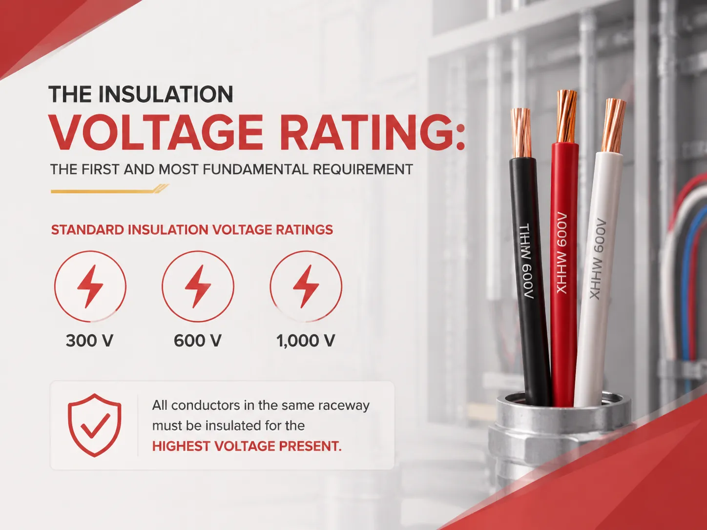
The Insulation Voltage Rating: The First and Most Fundamental Requirement
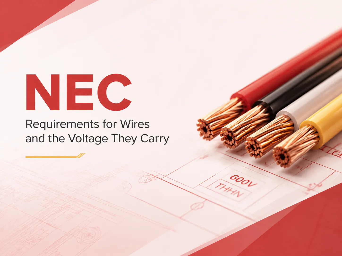
All types of conductors produced for wiring inside buildings are assigned a voltage rating indicated either on the insulation or on the cable sheath. The voltage rating means the insulation is able to withstand the indicated voltage on a continuous basis and is the first thing the electrician or inspector will look at to check if a specific conductor can be applied for a specific circuit. As per standard practice in low-voltage building installations, 300 V, 600 V, and 1,000 V are considered standard insulation voltage ratings. Conductor wiring that can withstand 600 V insulation voltage, which is widely used for residential and commercial branch circuit wiring, including THHN, THWN, and XHHW conductors is suitable for the application of any kind of circuit up to 600 V. Conductor wiring that can withstand 300 V insulation voltage is often applied for equipment wiring, fixture whips, and some control cables and can only be used for circuits that utilize up to 300 V of electricity.
Although the NEC’s rule, which is stipulated in Article 310.4, is straightforward in concept, it has a particular meaning that is not always recognized. In essence, all conductors that are placed in a raceway, a cable, or an enclosure must be insulated in accordance with the highest rated voltage found in the raceway, cable, or enclosure. Therefore, if the conduit contains 120‑volt lighting conductors as well as 480‑volt motor conductors, then all the conductors in conduit must be insulated in accordance with voltage of at least 600 volts. The insulation of 120‑volt conductors cannot consist of 300 volts insulation even though the conductors have only 120 volts; the conductors are together with those conducting higher voltages, and therefore all the wires installed in the same conduit must be rated for the maximum voltage present in the wiring. The NEC provides a second possibility: conductors with various voltages can share the same raceway if they are insulated from each other with help of non-conductive barriers, although it is extremely rare for the equipment to be installed in the field. The typical practice is to cover the mixed voltage wiring with help of conductors which are rated for 600 volts, which best explains why the conductors with this rating are used for almost all industrial and commercial wiring. The National Fire Protection Association (NFPA), which publishes the NEC, provides the complete text of Article 310 and the associated tables that define insulation ratings, ampacity, and installation conditions for every conductor type.
Ampacity and Conductor Sizing: The Relationship Between Wire Gauge, Temperature, and Current
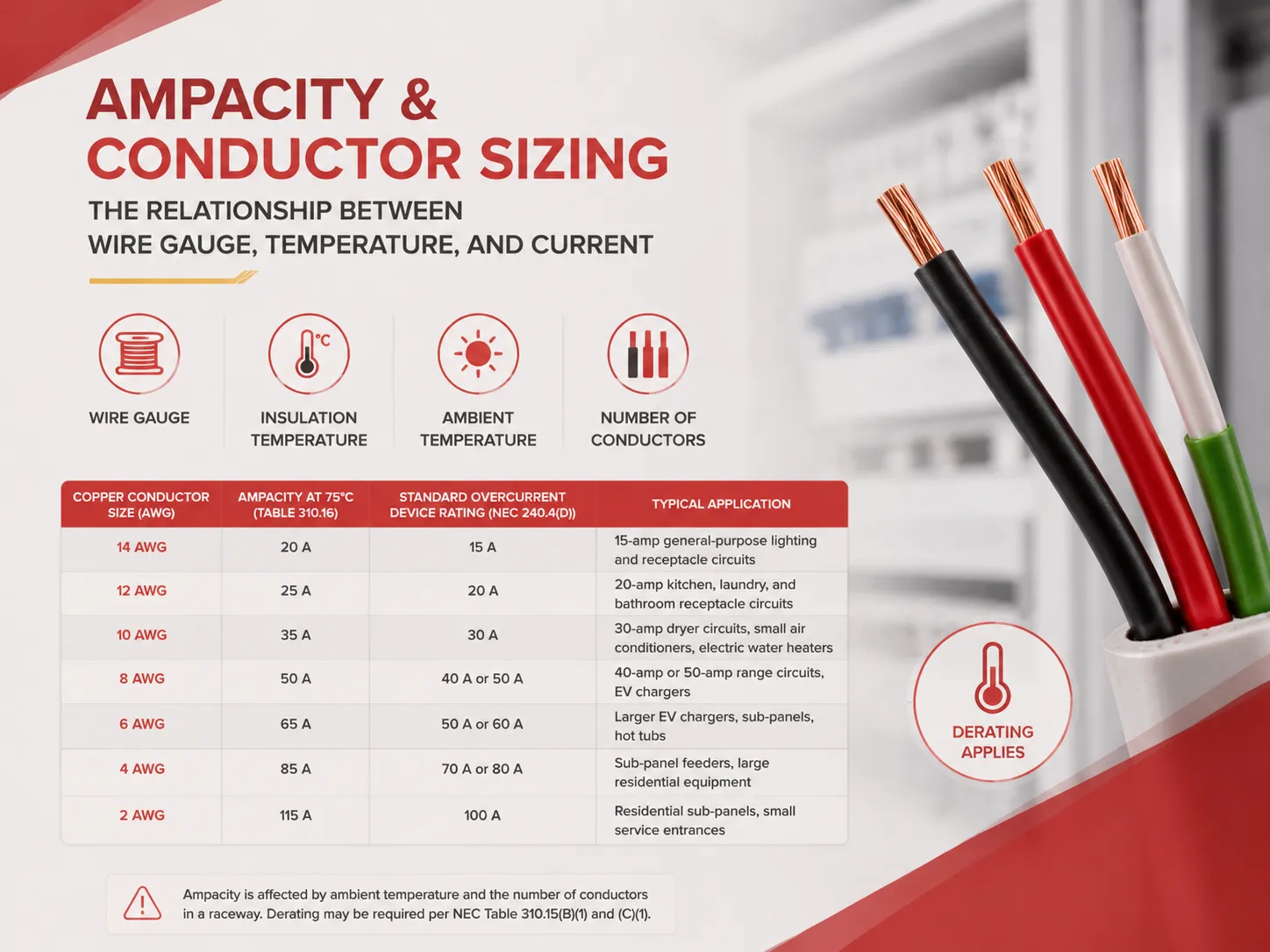
In a conductor, voltage remains a significant factor, however, it is not the only determinant of the conductor dimensions. Moreover, the conductor size is supposed to accommodate the current required by the load, and the size depends on factors such as the conductor gauge, insulation temperature rating, ambient conditions, as well as the amount of currents travelling in the racetrack. Ampacity tables according to the NEC – specifically, Table 310.16 facilitated calculation of the maximum permissible amount of current for the type of conductor based on its gauge. For instance, a 12-gauge copper conductor with insulation rated for 75˚C can accommodate 25 amps (despite the fact that the NEC has limited the amount of current to 20 amps for the circuit) due to the fact that in terms of its regulations, small conductors are more prone to overheating problems. In the table below, various ampacity data is summarized for copper conductors used in building wiring according to NEC temperature rating standard (75 C).
| Conductor Size (AWG, Copper) | Ampacity at 75°C (Table 310.16) | Standard Overcurrent Device Rating (NEC 240.4(D)) | Typical Application |
|---|---|---|---|
| 14 AWG | 20 A | 15 A | 15‑amp general‑purpose lighting and receptacle circuits |
| 12 AWG | 25 A | 20 A | 20‑amp kitchen, laundry, and bathroom receptacle circuits |
| 10 AWG | 35 A | 30 A | 30‑amp dryer circuits, small air conditioners, electric water heaters |
| 8 AWG | 50 A | 40 A or 50 A (depending on load and application) | 40‑amp or 50‑amp range circuits, EV chargers |
| 6 AWG | 65 A | 50 A or 60 A | Larger EV chargers, sub‑panels, hot tubs |
| 4 AWG | 85 A | 70 A or 80 A | Sub‑panel feeders, large residential equipment |
| 2 AWG | 115 A | 100 A | Residential sub‑panels, small service entrances |
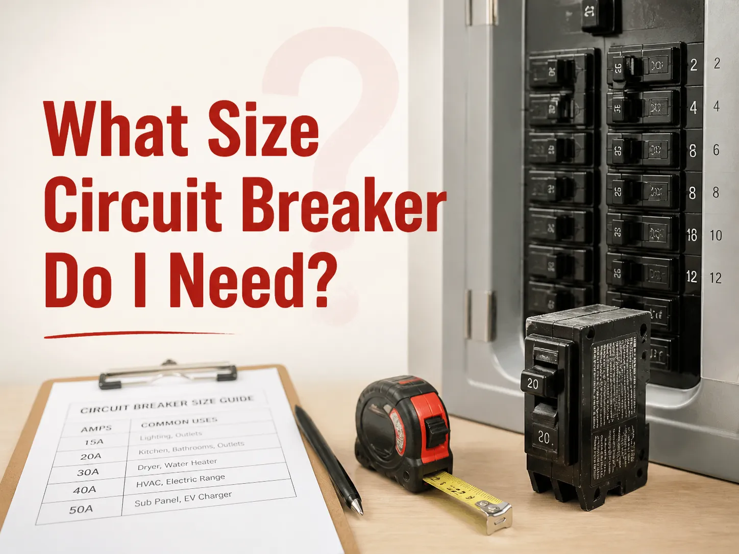
Ampacity figures are subject to modification based on environmental factors and number of conductors present in a raceway. In an instance where a conductor is used in a hot attic, where the ambient temperature surpasses the standard reference temperature of 30°C (86°F), it has to be derated where its permissible ampacity is decreased by the multipliers in Table 310.15(B)(1). Also, a raceway that has more than three current-carrying conductors should be derated according to the figures provided in Table 310.15(C)(1). As a result, the reduction of allowable ampacity of the conductor takes place, and such wire may be incorrectly sized for the circuit above temperature. For help with the specific calculation for any circuit, our guide on what size circuit breaker you need walks through the NEC‑based process for both general and motor loads, including the derating factors that apply to bundled and high‑temperature installations.
Voltage Drop: The NEC’s Recommendation That Becomes a Requirement in Practice
Voltage drop is not a requirement that must be followed according to the NEC; rather, it is simply a general guideline that many types of projects follow. For the most part, voltage drop recommendations by the NEC are followed by many engineers. As per Article 210.19(A) Informational Note No. 4, the NEC recommends that a branch circuit should not show a voltage drop value exceeding 5%, where there shouldn’t be more than 3% located on the feeder and maximum of 2% present on the branch circuit. The NEC guidelines state that a 120-volt load should be receiving a voltage supply of up to 114 volts. Likewise, in the case of 240 and 480-volts loads, respective values provided are 228 volts and 456 volts.
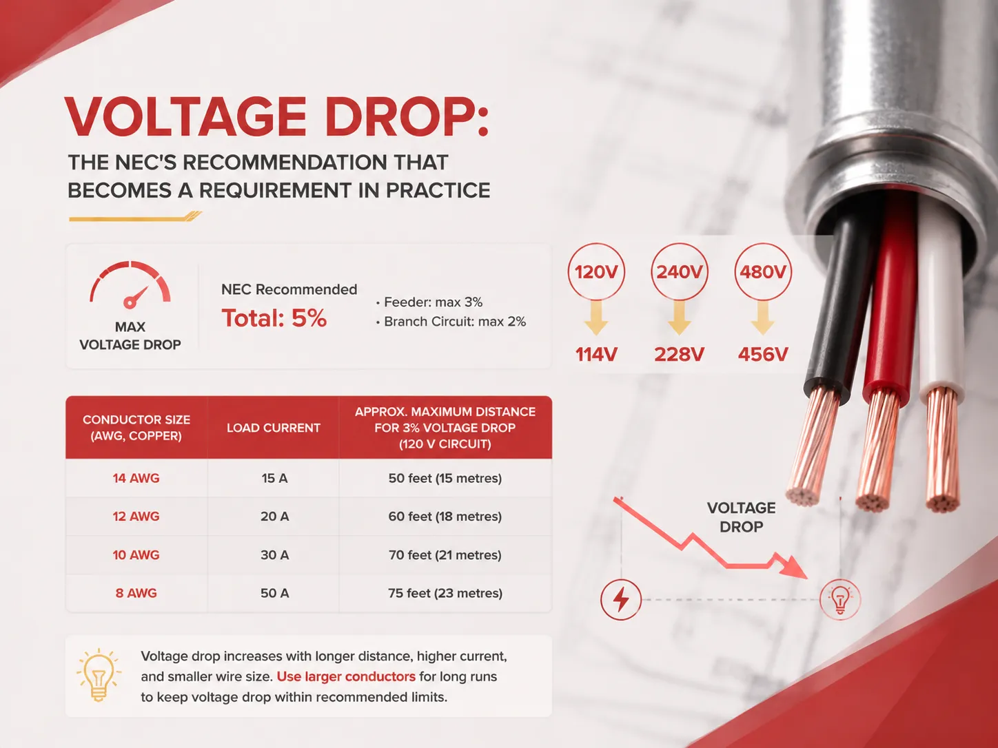
The voltage drop is determined by the length of the conductor, the size of the conductor, the amount of current flowing through it, and the voltage of the supply. The same conductor made of 12-gauge copper that is used to carry 20 Amperes without observable voltage drop over a distance of 50 feet will experience the drop of about 6% when the distance increases to 200 feet, which is greater than acceptable according to the National Electrical Code and could lead to some problems with dimming of light bulbs, overheating of motors, and malfunctioning of electronic devices. This problem can be resolved by increasing the size of the conductor, using a 10-gauge copper conductor or even an 8-gauge one for the distance of long runs, so as to ensure sufficient resistance and acceptable range of voltage drop. In the table below, the above mentioned maximum lengths of different sizes of conductors and loads are provided.
| Conductor Size (AWG, Copper) | Load Current | Approx. Maximum Distance for 3% Voltage Drop (120 V Circuit) |
|---|---|---|
| 14 AWG | 15 A | 50 feet (15 metres) |
| 12 AWG | 20 A | 60 feet (18 metres) |
| 10 AWG | 30 A | 70 feet (21 metres) |
| 8 AWG | 50 A | 75 feet (23 metres) |
These distances are approximate and should be calculated precisely for the specific installation, using the actual load current, the actual conductor length, and the applicable NEC voltage‑drop formula. Online calculators and mobile apps, many of which are referenced by industry organisations such as the Electrical Contractor Magazine, provide a convenient way to perform these calculations in the field, but the underlying formula — Vd = (2 × L × I × R) / 1,000 for single‑phase circuits, where R is the conductor’s resistance per 1,000 feet from the NEC’s Chapter 9 Table 8 — is straightforward and can be computed with a standard engineering calculator.
The 125% Rule for Continuous Loads: Sizing Conductors for the Long Haul
The 125% rule by NEC is one of the commonly misinterpreted provisions in the code. It influences the size of the conductor required to be used in a circuit. Simply speaking, continuous load is described in the NEC as the type of load that operates for a minimum of 3 hours. In this case, the conductors used for the circuit must be calculated based on 125% of the continuous load along with 100% of the non-continuous load. For instance, if we have a circuit with 16A continuous load (e.g. water heater), it will produce 20A rating — 16A * 1.25 = 20A. This indicates that 12-gauge copper conductor is the smallest conductor that can be used for such load. For reference, a 14-gauge copper wire would be too small since it has 15A capability. In addition to that, the rule applies to the overcurrent protective device: the circuit breaker is also sized at 125% of the load. So, for instance, in our 16A case we will have to use 20A circuit breaker. That is why so many residential circuits (particularly home heating systems, normal lightning circuits in buildings, and data centers) use 20A circuit with 12-gauge wire instead of complying with the code since the code requires that and it protects the wires from heat generated from continuous use. The Electrical Contractor Magazine and the UL provide extensive guidance on the application of the 125% rule in both residential and commercial installations.
The 83% Rule: When the Service Entrance Conductors Are Sized Differently
The 83% rule by NEC is an important rule for residential service entrance conductors. Under NEC Article 310.12(A), the service entrance conductor for a single-family dwelling can be calculated at 83% of the service rating, which is different from the normal practice where a 200-amp residential service is calculated based on the full load requirement as it would have been done for a commercial service of 200 amps. The 83% rule considers the diverse nature of the electrical load supply in homes, whereby it is not likely that all the appliances, lights, and receptacles being used are running at full load. Thus, 200-amp service can work using 2/0 AWG copper wire, which can supply the current at a rate of 175 amperes at a temperature of 75°C, unlike the 3/0 AWG copper wire that would be used in a 200-amp commercial system. In addition, the 83% regulation is only for the service entrance conductor, which is the cable that is connecting between the utility connection point and the main disconnect switch of a home, but does not apply to the feeder conductors, branch circuit conductors, or any other service in downstream services. Furthermore, the 83% rule only applies for single-family shit and it would make sense for all other sectors to have their service conductors calculated based on the load requirements and the overcurrent device rating.
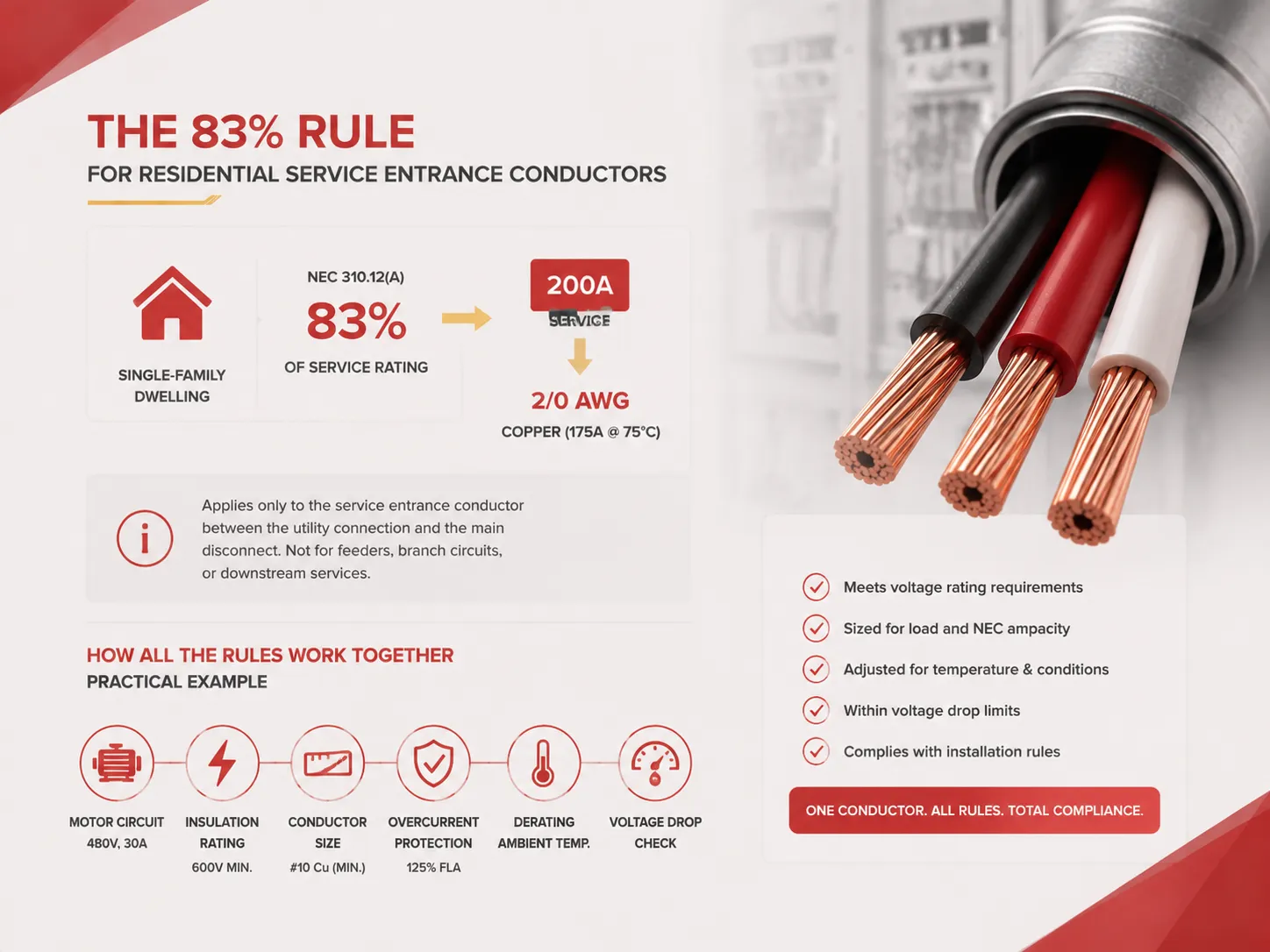
How All of These Rules Interact: A Practical Example
The NEC’s specifications regarding wires and their voltage levels are interrelated rules that must all be met by a single wire. For instance, a manufacturer may use a three-phase type of motor circuit of 480 volts and 30 amps. The wire must have a minimum rating of 600 volts insulation because the voltage of 480 volts is related to the low-voltage systems that require wires with 600 volts insulation. The wire must meet the requirement for the wire size to be equal to or larger than the current of the motor when it is fully loaded. For a motor running at 30 amps and 480 volts, the wire may be a #10 copper wire. However, due to the specific NEC motor circuit regulation stating that an overcurrent protection system must withstand 125% of a motor’s full-load current (when used with the continuous-duty motors), the size of a wire may be bigger than #10 copper wire. Moreover, the wire must also be derated in case of hot weather conditions; for instance, a factory ceiling can be derated in summer to then increase the dimensions of necessary wires. The wire dimensions must also be checked with regard to the voltage drop issue; for instance, a wire of 300 feet running at 480 volts can be #8 or #6 wire depending on the constraints imposed by the voltage drop. The wire is also required to share the system with wires having the same electrical insulation rating greater than 600 volts. The conductor used for one motor has to meet all these different requirements.
Frequently Asked Questions
What is the 125% rule in the NEC?
According to NEC Article 210.19(A)(1), the conductors and the protection against overcurrent device must have a size of 125% of the continuous load plus 100% of the non-continuous load for a continuous load which is a load functioning for three hours or more. Therefore, for a continuous load of 16 amps, conductors must have a size equivalent to 20 amps and a 20-amp breaker. The rule helps to maintain thermal safety by preventing the wires from overheating while running continuously for long hours.
How to find the voltage amount going into wires?
In order to measure the voltage on a conductor, a digital multimeter tuned to measure AC voltage is used with the measuring probes placed in such a way that one of them is connected to the conductor while the second is attached to the ground wire of the circuit. The voltage of a wire can be measured only when the wire is live, and the measurement can be performed only by a certified electrician using the right testing devices as well as the safety gear. The voltage that the conductor can hold is indicated on its insulation, and it usually equals 300 or 600 volts for building wire insulation, although this voltage should not be confused with the actual voltage present on the conductor at the time of measuring.
What is the NEC 5% voltage drop rule?
According to the guidelines presented in Article 210.19(A) Informational Note No. 4 of the National Electrical Code (NEC), it is advised that the maximum overall voltage drop in a branch circuit does not surpass 5% of the supply voltage, and this should include the feeder’s drop of 3% and the branch circuit’s drop of up to 2%. Although it is merely a recommendation, it is still commonly adopted by many design specifications and building regulations. The voltage drop can effectively be reduced by using conductors with a larger gauge and by taking into account the active load current, the length of the wires and the supply voltage.
What is the 83% rule in the NEC?
Article 310.12(A) of the NEC explains the 83% rule, which states that for a single-family house the service entrance conductors may be sized to 83% of the actual service rating or load. This means that a residential service rated at 200 amps may use 2/0 AWG conductors instead of the larger 3/0 AWG copper conductor that would be required in a commercial application. However, the 83% only applies to single-family dwelling’s service entrance conductors, while all other conductors must be sized according to their actual ampacity, which is determined by the load calculations and overcurrent device ratings for those circuits.
References
- NFPA 70 — National Electrical Code (NEC). The foundational standard for electrical installation in the United States, including Articles 210, 240, 310, and the ampacity and voltage‑drop tables that govern conductor sizing and installation. National Fire Protection Association.
- UL — Wire and Cable Standards and Certification. The testing and listing standards that define the insulation voltage ratings, temperature ratings, and ampacity of building wire and cable.
- Electrical Contractor Magazine — NEC Application Guides and Voltage Drop Calculations. Industry publication providing practical guidance on applying the NEC’s conductor sizing, ampacity, and voltage‑drop rules in real‑world installations.
- Mike Holt Enterprises — NEC Training and Conductor Sizing. Educational resources on the NEC’s conductor sizing rules, including the interactive calculation tools and the detailed explanations of the 125% rule, the 83% rule, and the voltage‑drop recommendations.
The NEC requirements for wires and the voltage they carry are not a single table or a single rule. They are a web of interrelated requirements — insulation voltage rating, ampacity, voltage drop, continuous‑load sizing, and service‑entrance sizing — that together ensure that every conductor in an electrical installation is correctly specified for its voltage, its current, its distance, and its environment. The electrician who pulls a 12‑gauge conductor for a 20‑amp circuit, the engineer who sizes a 500‑kcmil feeder for a 400‑amp switchboard, and the inspector who checks that the conductors in a mixed‑voltage raceway are all rated for the highest voltage present are all applying the same NEC framework. Understanding that framework — and applying every part of it, not just the ampacity table — is the foundation of safe, code‑compliant electrical installation.