During a motor failure in a crucial conveyor line of a major food processing facility, the maintenance technicians did not have to search the cables through the conduits, stop all the production on the floor or waste their hours on determining which switch supplied the electricity to which motor. The professionals therejust walked into the Motor Control Center (MCC) — a single metal cabinet, placed on the floor of the electric room, opened the door of the needed motor’s bucket, disconnected it, locked it and carried out the repairs. The production line continued without interruptions. It means the MCC had done what it was designed for: bringing all motor controls, protections, and isolations into one single and easy-to-reach place. Неalthy andМ knowledgeable understanding of the MCCs and their functioning is something that everyone working with the industrial motor loads should possess. So, this guide contains everything readers need to know about the MCC, starting with its construction and elements, to power and principle of work.
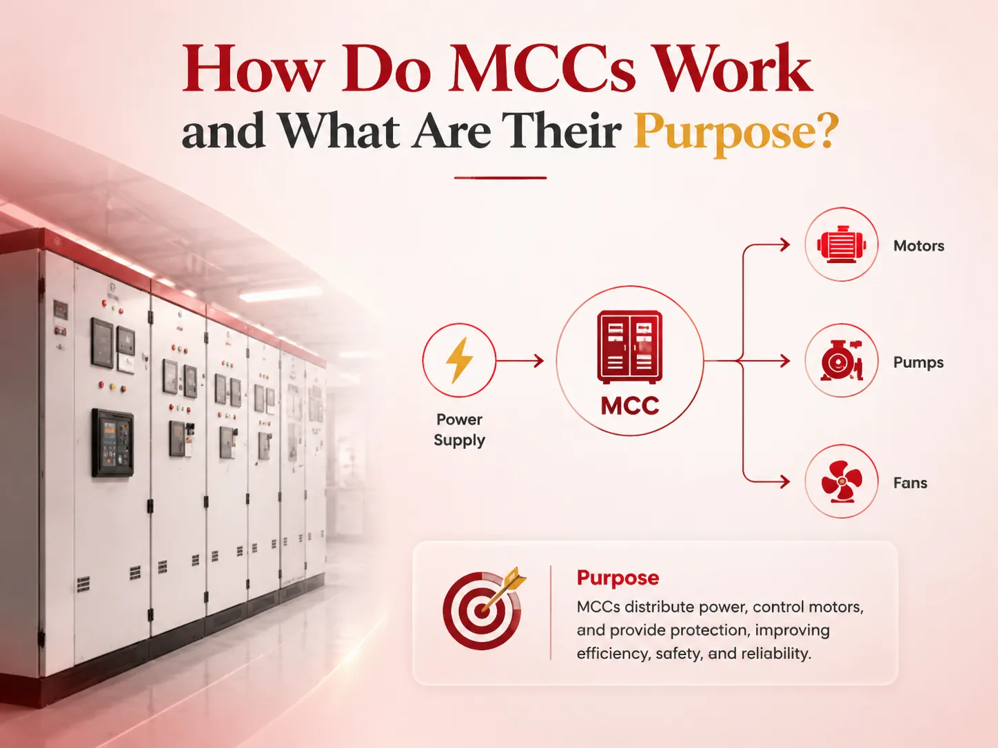
Summary: Motor Control Center (MCC) is a unit made up of several compartments of motor control units that provide a centralized and standardized operation of power distribution, motor starting, powered equipment protection and control functions for multiple electric motors. The process of work begins with the hardware receiving power from the system of bus bars then distributing power to motor controllers , which are also known as starters, contactors and soft starters. In addition to power distribution, MCC also provides the location for motor isolation, preventive maintenance and troubleshooting of equipment. Each motor is allotted a separate compartment within the structure in order to be provided with the circuit breaker, overload relay and motor control unit. The main function of the Motor Control Center is to increase efficiency of electrical engineering processes, reduce time on repairing electrical and control devices and increase safety of the operations.
What a Motor Control Center Actually Is
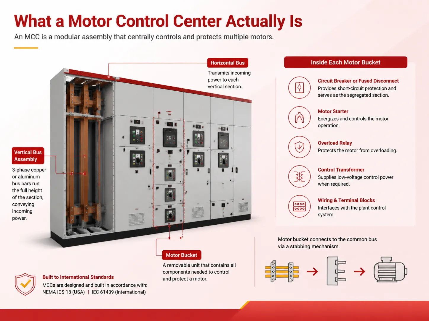
A metal enclosed floor standing structure called MCC is made of standardized vertical sections bolted together to make a consistent lineup of columns. The vertical sections contain vertical bus bar assembly system which normally consist of 3 phase copper or aluminum bars, which run throughout the length of these sections and convey the incoming power.
The sections are connected horizontally via a common horizontal bus, which transmits the incoming power from the feeder to the vertical sections. The bus bars form the electrical backbone of the MCC, since each motor bucket in the row uses these common buses to receive energy through a stabbing mechanism that allows the bucket to connect to the bus.
Each motor at the facility features a motor bucket which is a separate techer housing fitted into a specific slot of the MCC. The bucket itself has all parts required to operate the motor: circuit breaker or fused disconnect module that functions as the segregated section; motor starter that provides energization of the motor. The overload relay will protect the motor from being overloaded; control transformer for providing low-volt control power (should it be necessary) and sufficient wiring and terminal blocks for connecting the bucket with the control system of the plant. The bucket acts as a self-sufficient installation for motor control that can be used with any installation of the same or similar type, standardising and interchangeability being its main operating principal. And every motor installed at the plant has the same name and characteristics. The regulations for MCC are spelled out in NEMA ICS 18 document in the USA and in IEC 61439 standard internationally.
How Power Flows Through an MCC and Reaches the Motor
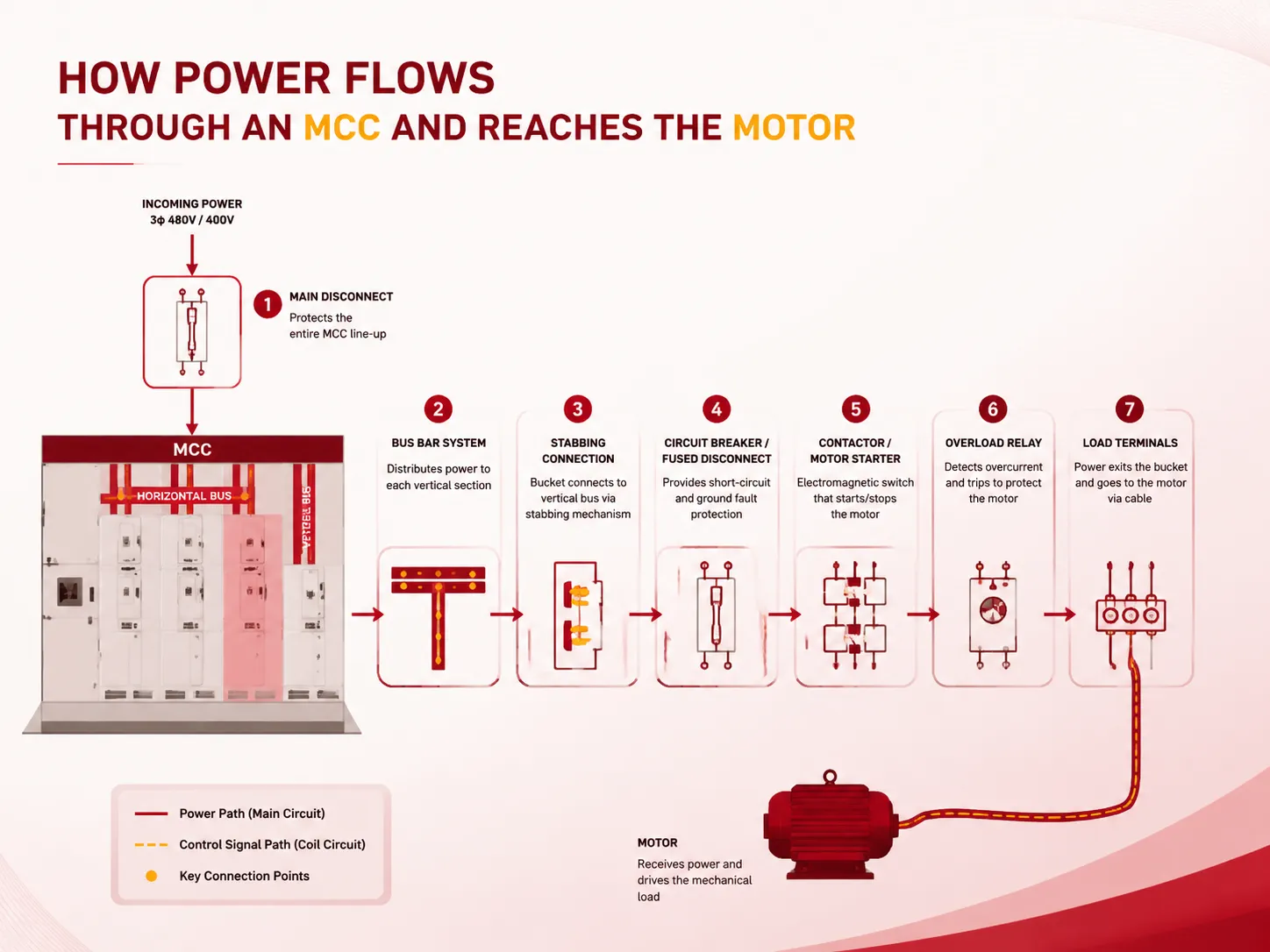
An MCC is an electrical arrangement that has an organized sequence of control and protective equipment, which has its assigned task. Understanding this sequence is crucial when diagnosing a fault in the MCC, replacing a device, or ordering a new bucket. The electrical path is as follows:
- Incoming power enters the MCC through a main disconnect – a circuit-breaker or fused switch – protects the whole line-up. The incoming feeder may be from a switchgear, a transformer secondary, or a distribution panel, usually at a voltage of 480V three-phase in North America or 400V in IEC markets.
- The main bus bar system distributes power to every vertical section. The horizontal bus runs on the upper part of the lineup and the vertical bus goes through the sections of the MCC. The bus bars are made accordingly to the total connected load of the MCC. The short-circuit withstand rating of the bus bars is equal to the maximum fault current that can happen at the place of installation.
- Each motor bucket connects to the vertical bus through a stabbing mechanism. Once the bucket is inserted into position, the spring-loaded jaws come into contact with the bus bars and are able to create a bolted-pressure connection for the full-load current of the motor. The stabbing mechanism ensures no need to de-energize the entire MCC in order to insert and remove the bucket.
- Inside the bucket, the power flows first through the circuit breaker or fused disconnect. This is the first safety assembly present in the bucket. It grants protection to the motor circuit against ground faults and short circuits, besides functioning as a local point for lockout/tagout during repair operations. Usually, the breaker is rated for the current of the motor at its full load and should be capable of interrupting the circuit strength, i.e. its breaking capacity must be equal to the short circuit rating of MCC.
- Power then flows to the contactor or motor starter. The contactor acts as an electromagnetically-driven switch that turns the power circuit on and off to initiate or halt motor operation. The control system causes the coil of the contactor to be activated and power flows to the motor in response to a start signal, typically transmitted through either 120 V AC or 24 V DC. The moment the stop signal is transmitted, the coil shuts down and motor operation is terminated. A motor starter combines the contactor and the overload relay into a single unit so that the terms are interchangeable in MCC applications.
- The overload relay is the final protective device before the motor. The overload relay is wired in series with the contactor and has the capability of detecting the current flowing to the motor through the use of the bimetallic strips or electronic current sensing devices. When the motor has a prolonged overcurrent — due to a mechanical blockage, bearing breakdown, or process overload — the overload relay gets heated and trips, thus interrupting the circuit in the contactor and connecting the motor in order to prevent overheating the windings. The relay is adjusted for the motor’s maximum current, usually at the level of 115% or 125%, depending on the type of battery and applicable laws.
- The power leaves the bucket through load terminals and is wired to the motor. The motor cable which generally consists of three conductors and a grounding wire and whose size is determined by total motor current and voltage drop over cable’s distance connects the load terminals of the bucket to the terminals of the motor. There can be a great distance of hundreds of feet between the motor and the MCC while the motor cable could be run in a conduit or cable tray.
The Purpose of an MCC: Why Centralised Motor Control Became the Standard
Before MCCs (Motor Control Centers) gained popularity in the 1950s and 1960s, industrial motor control was accomplished in a decentralized fashion, where every motor had its own starter, mounted on the wall in close proximity to the motors. Though this method was effective in achieving its intended purpose, it still had many disadvantages. Starters were placed in numerous locations throughout plants, sometimes in areas affected by dust, water or otherwise hard-to-access areas. Troubleshooting motor faults meant moving around the plant, possibly getting onto a platform or even a pit. In order to install a new motor, one had to install a new starter, connect it to the supply and run the cables from the switchboard.
The MCC tackled these challenges through the incorporation of all motor control equipment to a locale that is centralized, efficient, clean, and accessible. MCCs serve numerous but interrelated purposes:
- Centralised motor control and monitoring. Every motor in any part of the factory can be controlled and observed from just one point. The custodian of the factory does not have to go around and inspect each motor. A motor control center’s indicators, ammeters, and control buttons provide a unified point of control for an entire production region.
- Simplified maintenance and fault‑finding. Whenever a motor trips, the maintenance technician opens up the motor control center’s door, checks the trip indicator on the overload relay as well as the circuit breaker and lock and isolate the motor without entering the area of production into trouble. The bucket can be taken out, checked and placed back within a few minutes minimizing the downtime at work. A spare bucket can be kept in the warehouse and it can quickly replace the faulty one.
- Safe, accessible isolation points. All motor buckets have a nearby, secure disconnect system that is conveniently located in a well-lit electrical room. This enhances safety considerably as opposed to the conventional fused disconnect on the wall next to the motor that could find itself in dangerous, humid or narrow spaces.
- Space efficiency and reduced wiring cost. One MCC combines dozens of standalone box-type panel installations and reduces them into a single compact model. The shared bus bar system completely removes the need to install separate power cables to connect the electrical distribution panel and every motor.
- Scalability and flexibility. An MCC has been crafted with spare bucket areas. So, to add a new motor in the future, you just have to add a new bucket in the vacant area and lay the motor cable — there will be no need for a new enclosure, a new feeder, or any major overhaul.
How an MCC Differs from Individual Motor Controls and VFD Panels
An MCC is often misunderstood with various kinds of electrical equipment, and knowing their differences is key to selecting the right solution. The term MCC is given to a single entity that consists of multiple motor starters, all combined in a bus system. A VFD panel is a system placed either on a wall or on the floor; it allows for controlling a motor or a group of related motors with the help of the variable frequency drive and its equipment. The use of a VFD means that the frequency and voltage supplied to the motor can be adjusted – a function that cannot be performed by a conventional motor starter located in the MCC. However, it is also possible to incorporate VFDs into MCC blocks. In this case, a VFD block occupies the space in a standard MCC, while having a common connection and isolation capabilities of a standard starter block. Next comes MCP, which is the name for a circuit breaker providing only short-circuit protection for a motor circuit. The MCP has an adjustable magnetic trip, but there is no thermal overload element. An MCP operates in a combined motor starter alongside a contactor and an overload relay. For a detailed explanation of how MCPs differ from standard circuit breakers, our article on motor circuit protector vs circuit breaker covers the distinctions in protection, application, and code requirements.
The Components That Make Up a Typical MCC Bucket
Every motor bucket in an MCC contains a standard set of components, arranged in a sequence that reflects the electrical path from the bus to the motor. The table below summarises the key components and their functions.
| Component | Function |
|---|---|
| Circuit breaker or fused disconnect | Provides short‑circuit and ground‑fault protection for the motor circuit. Serves as the local isolation point for lockout/tagout. Must be rated for the motor’s full‑load current and the MCC’s short‑circuit rating. |
| Contactor | An electromagnetically operated switch that makes and breaks the power circuit to start and stop the motor. The contactor coil is energised by the control circuit. The main contacts are rated for the motor’s full‑load and locked‑rotor currents. |
| Overload relay | Protects the motor from sustained overloads. Senses the motor current through bimetallic strips or electronic sensors, and trips the contactor control circuit if the current exceeds the set threshold for a defined time. Set to 115–125% of the motor’s full‑load current. |
| Control transformer (optional) | Steps down the incoming 480 V or 400 V to the control voltage — typically 120 V AC or 24 V DC — that powers the contactor coil, the pilot lights, and the control relays. |
| Pilot devices | Start and stop pushbuttons, selector switches, and indicator lights mounted on the bucket door for local control and status indication. |
| Terminal blocks and wiring | Connect the bucket’s internal components and provide the interface to the external control system — PLC inputs and outputs, remote start/stop signals, and motor temperature sensors. |
What Is the Typical Life Expectancy of an MCC?
Motor Control Centers that are properly cared for, kept in clean and dry conditions, and operated within their specified limits can serve between 25 and 35 years, or even longer. The steel casing, copper bus bars, and structural frame can easily be considered as some of the strongest elements in the construction of the unit, as they can remain intact for as long as the building. At the same time, the parts that need to be changed from time to time — circuit breakers, contractors, and overload relays — are the weakest parts, as their service life depends on the frequency of motor use, the type of load, and the working environment. Thus, a contractor that start a motor six times every hour will last less than a contractor that starts the same motor only once a day. Moreover, an overload relay that works under high ambient temperatures or in dusty or wet environment will fail sooner than the one that is stored in a climate-controlled switch room. Thus, the most effective way to prevent failures is to inspect all control center buckets once a year through thermal scanning of the bus bars and circuit breakers, visual checking of the contactor contacts for burns, calibration and cleaning of the interior.
Frequently Asked Questions
What does a motor control centre do?
The functions of power distribution, motor starting, overload protection, and electric motor control are gathered in one enclosure by means of a Motor Control Centre (MCC). The MCC not only makes it easier to isolate and maintain electrical motors in a secure place but also minimises the difficulties arising in the process of troubleshooting, helping achieve an overall simplicity of the system and avoiding troubles with wiring as compared to distributed electric motor starters installed throughout the plant.
What is the difference between a MCC and a VFD?
An MCC is an intricate assembly that includes motor starters, circuit breakers and control equipment for various motors assembled into a common bus structure. VFD (Variable Frequency Drive) refers to a single device that controls motor speed by varying the supply frequency and voltage to the motor. Thus, VFD can be installed within the MCC bucket that also provides a platform for operation across bar starters.
What is the difference between MCC and MCP?
An MCC is an entire Motor Control Center — the metal‑enclosed assembly that contains multiple motor buckets and a common bus system. An MCP (Motor Circuit Protector) is a specific type of circuit breaker that provides only short‑circuit protection, with an adjustable magnetic trip and no thermal overload element. An MCP is a component within an individual motor bucket in the MCC; it is not an alternative to an MCC. Our detailed comparison of MCPs and standard circuit breakers explains the functional and code‑driven differences.
What is the life expectancy of a motor control center?
A well‑maintained MCC in a clean, dry, indoor environment has a typical service life of 25 to 35 years or more. The structural enclosure and the bus bars can last for the life of the facility. The wear components — circuit breakers, contactors, overload relays — have shorter lives, typically 15 to 25 years, depending on the frequency of motor starts, the severity of the electrical load, and the operating environment. Annual inspection and preventive maintenance extend the life of every component.
References
- NEMA ICS 18 — Motor Control Centers. The North American standard that defines the design, construction, testing, and performance requirements for Motor Control Centers, published by the National Electrical Manufacturers Association.
- IEC 61439 — Low‑Voltage Switchgear and Controlgear Assemblies. The international standard governing the design and testing of MCCs and similar assemblies, adopted across Europe, Asia, and many global markets.
- Eaton — Motor Control Centers: Freedom 2100 and FlashGard. Manufacturer of MCCs for industrial and commercial applications, with technical documentation covering bucket selection, bus ratings, and arc‑flash safety features.
- Schneider Electric — Model 6 Motor Control Centers. Manufacturer of MCCs with integrated power monitoring and smart motor control capabilities, with application guidance for heavy industrial and process applications.
A Motor Control Center is the electrical hub of an industrial facility — the single point where every motor’s power, protection, and control converges into a standardised, maintainable, and expandable system. Learning how an MCC operates — the bus bars carrying voltage from the incoming line, the buckets that house and control each motor, the sequence of equipment from the power supply to the motor — is essential for industrial electrical maintenance, troubleshooting, and design. The MCC creates a unit out of what was previously scattered, unifies what was once done spontaneously, and enables the required safe disconnection as well as modularity of devices. Any electrician performing maintenance, engineer selecting components, and production site manager using the MCC will characterize that device as trusting and stable.