
In most cases, electric motors do not get damaged due to short circuits. Usually, they stop functioning due to getting overheated because of continued operation at 110% of the rated current for 40 minutes due to dry bearings or restricted flow through pumps or other similar faults that have gone undetected by everyone until the winding insulation has failed. The only device capable to notice the malfunction is an overload relay, which is the cheapest protective part of the motor starter.
The information given below explains what the overload relay provides in the motor control circuit, how each type of relay works, which trip classes to select, what causes tripping, and how to set the relay.
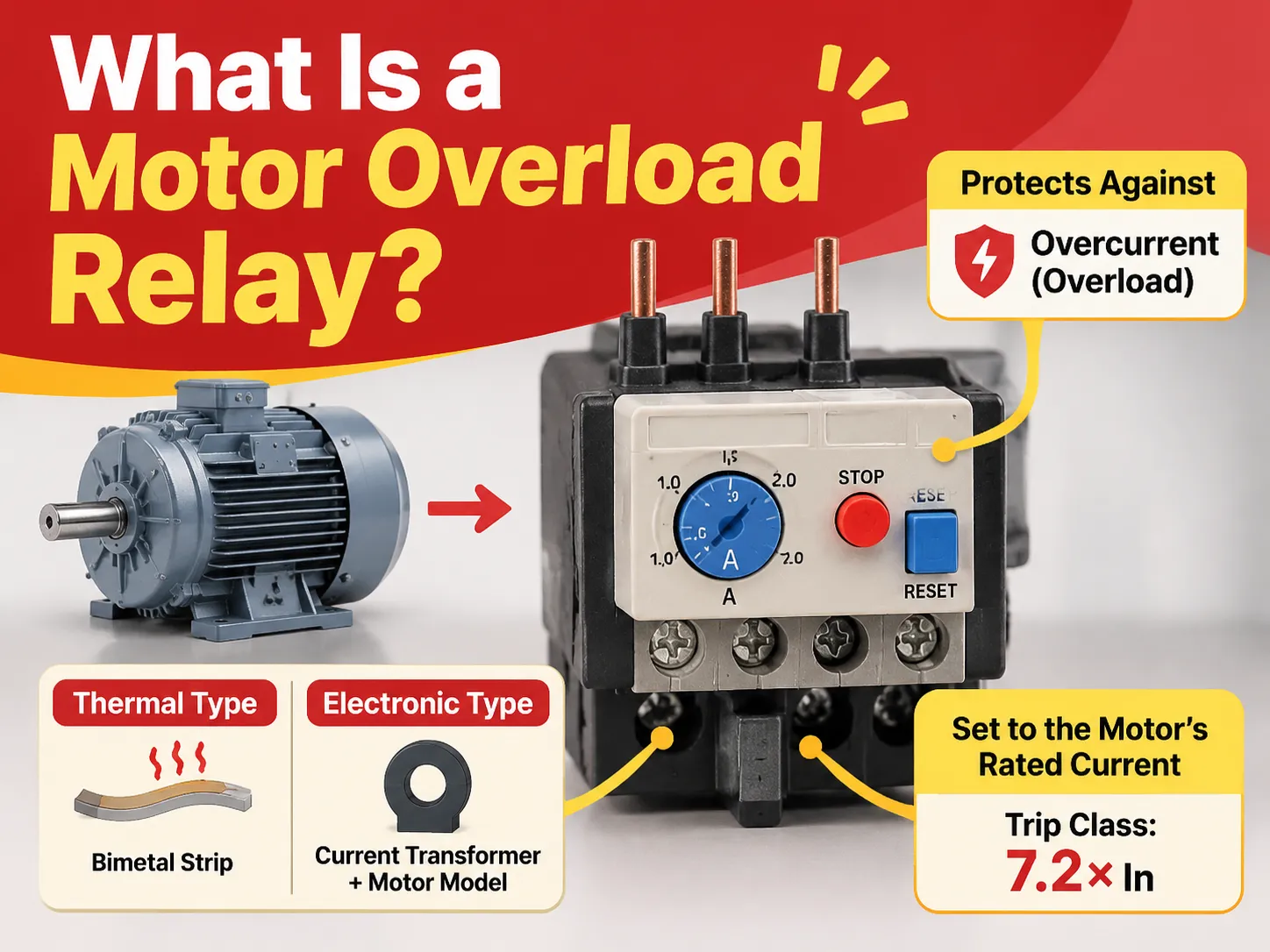
Briefly put, a motor overload relay is a device in a motor starter that measures current and cuts off the control circuit if the motor consumes too much current for too long. Therefore, this device provides no short circuit protection, which is fulfilled by the circuit breaker. The thermal types use bimetal strips heated by the current, while electronic types rely on current transformers and a model of the motor. The setting is the rated current of the motor, while the trip class defined at 7.2 times that current must consider the time of the motor start.
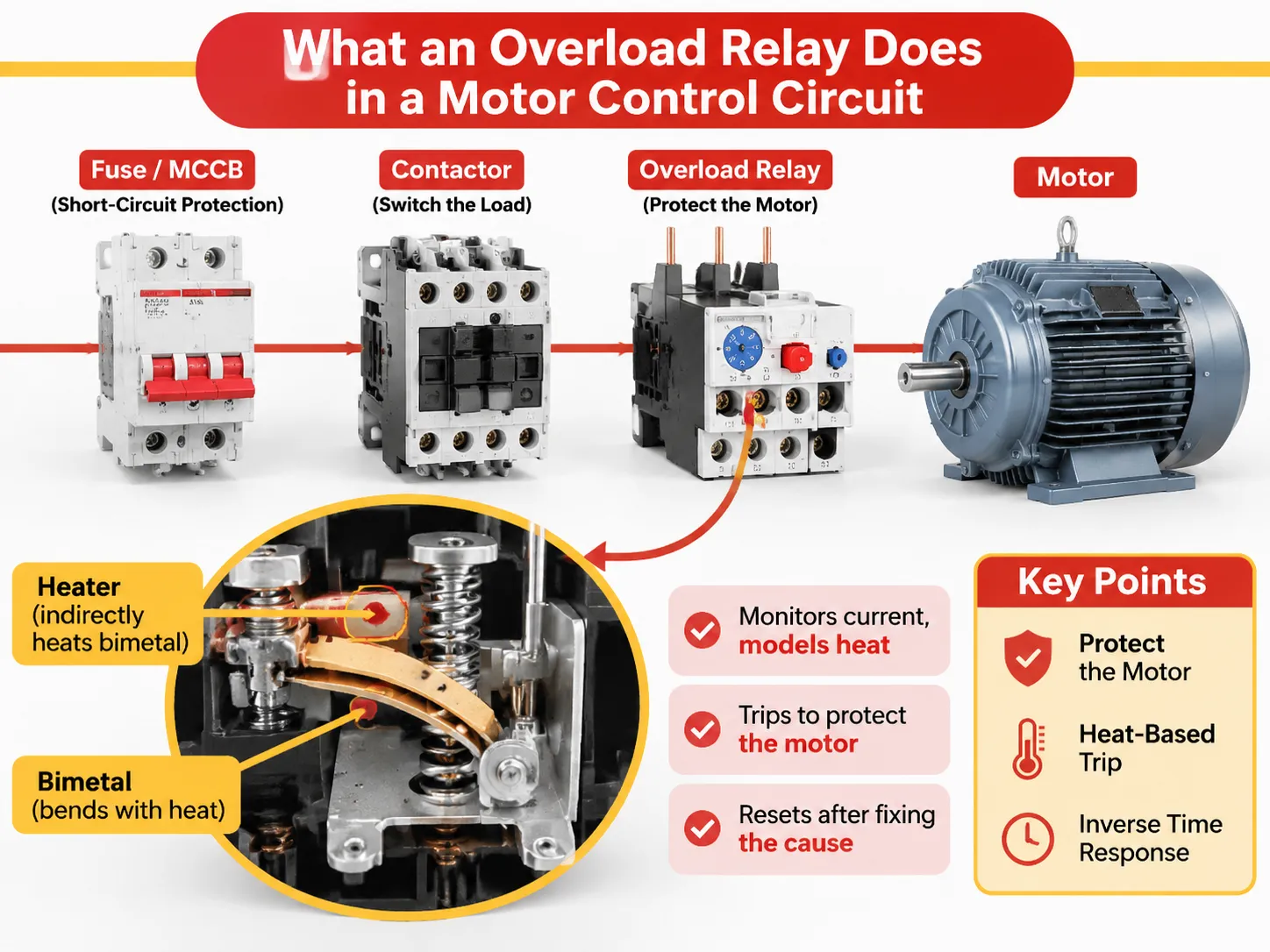
What an Overload Relay Does in a Motor Control Circuit
The electric overload relay has a specific role in motor control. The purpose of an overload relay in the system is to protect the motor against the burning of the winding than protecting the cable or the contactor. This is something that explains a lot in the process of setting this machine.
The protector will act in different situations, so every device will be responsible for its type of failure. The first one is a short circuit device such as fuse and a molded case breaker which can cope with the short-circuit current of up to kiloamps literally in milliseconds. The second type of protector is the contactor that uses electrical work when switching on the load. The overload relay is used in between both devices to identify when the motor operates at the condition of the damaged motor winding and overheated engine.
So it works according to its primary function and does not allow the engine overheating or getting damaged. When detecting a fault, the relay opens a small contact which is used in the contactor circuit. After the contact of the contactor breaks down, the motor stops working but the relay requires manual resetting.
So in fact, the relay guards thermal capacity of the motor as current is just the indirect indicator of it. If the motor is running hot, it will be harder for the relay to stop the engine than if the appliance is running in cold mode since it has to take into consideration the accumulated heat of the motor prior to its operation.
The practice shows that if the motor has proper protection, it does not matter how big the relay is. The main problem with the relay is whenever it works or not, increasing the relay capacity does not mean anything unless the main root cause of the issue is discovered.The integrated version of the whole assembly, contactor plus overload plus enclosure, is what a motor starter of this type packages, and buying it as one unit removes the mismatch risk between contactor and relay that causes most installation errors.
How a Motor Overload Relay Works, Type by Type
The market is characterized by two predominant mechanisms and one mechanism that has just emerged.
- The first one is the Bimetal, which uses indirect heating. Each phase goes through an element heated by the bimetallic component, which consists of two different metals that expand at different rates so that it bends with heat. When bending, it acts on the bar of summation and a lever, which releases the snapping mechanism and opens contact 95-96. Indirect heating means that the heater is responsible for heating the bimetal as opposed to electric current transmitting heat through the bimetal. The advantage is that it is possible to use one frame for different current levels by changing the heater.The result of such design is that inverse time effect is achieved. At double-rated current the bimetal bends slowly, at six times the current the bend is fast. This corresponds to the physical behavior of a motor, which has capability to withstand high current for a short time and low current idling. There is a different bimetal for compensation purposes which cancels ambient temperature influence.
- The second type is Electronic. Current transformers monitor the current value for each phase, and based on that an electronic circuit makes a decision according to the thermal model and activates a small relay or a transistor switching the circuit on. There is no heater in this process – and DVR is capable of switching various currents just by changing the setting.Such electrical devices are used for motor protection, combining in one device the functions of magnetic short-circuit and thermal overload devices.
No matter what type of protection is used, the electrical connection is the same: the terminals 95-96 are the normally-closed tripping contacts connected in series with the contactor coil while terminals 97-98 are normally-open and used either as indicating contacts or to signal PLC. The relay connected through the terminals 97-98 instead of terminals 95-96 would never trip, and this mistake occurs often enough to be checked by the meter every time one receives a panel. The coil side of the same circuit is covered in these AC contactor specifications, which give the coil voltages that the control circuit has to match.
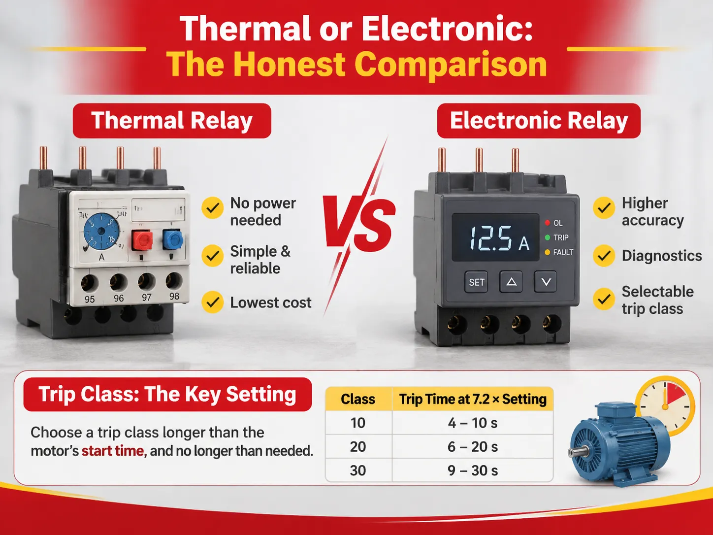
Thermal or Electronic: The Honest Comparison
Both are correct answers for different jobs, and the price difference is smaller than the feature difference.
| Factor | Thermal (bimetal) | Electronic |
|---|---|---|
| Accuracy | ±10% to 20% around the setting | Typically ±5% or better |
| Ambient compensation | −20 to +60 °C on most frames | −25 to +60 °C, wider on some |
| Trip class | Fixed at purchase, usually Class 10 | Selectable, often 5E to 30E |
| Thermal memory | By physical cooling, which is realistic | By model and stored state |
| Diagnostics | Trip or no trip | Current per phase, thermal load, trip cause |
| Price | Lowest | Two to five times thermal, falling |
| Best for | Standard pumps, fans, simple starters | Critical drives, high-inertia loads, networked plants |
The drawback of the thermal relay is that it utilizes bimetal that operates in the same way as the motor but not in the way that eliminates its shortcomings. The thermic relay does not indicate the reason for tripping and is affected by the temperature in the panel. Furthermore, the accuracy of the thermic relay is affected by other factors, such as the heater tolerances.
The drawback of the electronic relay is its dependency on correct settings and power supply. If there is a problem with the output, no signal will be emitted. However, there is a benefit due to the fact that the readings obtained from the electronic relay can be utilized by the maintenance team for other applications. The behaviour of the contactor side under the same duty is set out in these AC contactor selection and wiring guidelines, because a relay protects a motor only if the contactor survives long enough to interrupt it.
Trip Class: The Setting That Causes Most Nuisance Trips
According to the IEC 60947-4-1 standard, the trip class refers to the time taken to trip at 7.2 times the preset current when a motor is cold. It was developed to allow motors to go through the startup process without sensing current until the motor stopped entirely.
| Class | Trip time at 7.2 × setting, from cold | Typical load |
|---|---|---|
| 10A | 2 to 10 s | Fast-starting, low inertia, hermetic refrigeration |
| 10 | 4 to 10 s | Pumps, fans, small conveyors, general duty |
| 20 | 6 to 20 s | Loaded conveyors, compressors, larger fans |
| 30 | 9 to 30 s | Crushers, mills, centrifuges, high-inertia loads |
The demand for usage of tolerance band E in electronic relays is that the minimum rates for the classes are lower than for others, 3 seconds for 5E, 5 seconds for 10E, 10 seconds for 20E, and 20 seconds for 30E with the upper rates being equal to the one for other classes.
In order to decide on the proper trip class, the initial requirements can be put simply: it should be longer than the leading time of the motor. Still, despite the simplicity of the described rule, there is a risk of making a mistake while selecting a relay. When using Class 10 relay with a motor taking 14 seconds to reach working speed, it will trip at every attempt, so the temptation will be to adjust the setting current instead of changing the class of the relay, which will allow fixing the problem but deprive the motor of protection.
The people often make mistakes when calculating the possible current in case of using the star-delta starter. The current flowing through the overload relay installed on the main contactor is equal to 0.58 of the nominal current of the motor. If there is an additional overload relay protecting the motor during the star phase, it will be set to work at one third of the current value.
What Causes an Overload Relay to Trip, and What Does Not
The list of real causes is small compared to the long list of alleged causes associated with overloads.
A motor overload takes place when the effective current exceeds the rating for long enough to exceed the thermal limit. There are four major causes of overloads: mechanical issues, like a stuck bearing, or the impeller being blocked or misaligned; supply problems, such as low voltage, where the current increases; usage changes, such as the workpiece being heavier, or the damper being shut; and a failed start, where the motor does not change its speed and remains in the blocked current mode.
However, one must note some mistakes people make in their overload interpretations. Some of them are: a short circuit related to the breaker; a ground fault, requiring protection by the RCD; burnt-out main contacts of a contactor leading to an open circuit; and a fault in the control circuit manifesting in a failure of the latch-up. The last one is the most common misinterpretation since it produces the very same symptom: complete stoppage of the motor, which has to be restarted. A contactor that has lost a phase through contact erosion will draw more current on the remaining phases and will look exactly like an overload until someone inspects it, and the symptoms of that failure are set out in this look at AC contactor failure symptoms.
Repeating trips on a motor used for years is a mechanical, not a signal issue. Repeating trips on a new installation is most likely a setting or class fault. Any trips occurring only during the summer are likely to be temperature related. Any trips upon starting are likely to be a class fault or a star-delta setting fault. The fastest way to classify a trip is by its timing.
Setting the Dial: Rated Current, Not Tripping Current
The dial is calibrated according to the motor’s full-load current rating written on the nameplate and not to a value that prevents it from tripping. The standard IEC 60947-4-1 specifies that the relay should not trip under conditions where the current exceeds this value by a factor of 1.05, and it must trip within 2 hours where the current exceeds it by a factor of 1.2. The value on the dial becomes the starting point for the drawing of the inverse-time characteristics for the relay.
The typical range of the settings is 1.5:1, for instance 7.5-11 Amperes, and should ensure that the motor works within the specified range instead of at the extreme values to allow for small readjustments afterwards. In situations when the motor’s service factor exceeds 1.0, it would be reasonable to set it slightly higher than that specified in the nameplate information. If the service factor is equal to 1.0, then it should be set according to the nameplate data or slightly below this figure.
Once the commissioning is complete, the following three steps should be adhered to. The running current of the completed set-up should be measured and compared with that of the nameplate. The setting itself must be recorded on the panel schedule. The last step would be to choose the mode of change, manual or automatic, depending on whether a person will observe the equipment or not.
Where Phase Loss Changes Everything
Single phasing may create the most hazardous overload condition that a three-phase motor will have to face. When one phase has failed and the motor continues to run on two phases, the current flowing through the remaining windings rises sharply and takes up some of the bimetallic relay’s current load. A plain three-bimetal relay could be slow enough to allow for a first profession of winding failure.
The phase-loss-sensitive construction, sometimes referred to as differential, will incorporate a second summing bar that senses the difference in deflection between phases. An unbalanced-represented or missing phase will trip the relay faster than a symmetric overload with the same magnitude. The published figures bring the effect down to earth. On one common relay family, the ultimate trip current is 120% of full load, and with phase loss, it is 115%. Modern IEC relays are phase-loss-sensitive by default; older stock and cheap imports are often, and the data sheet does not always say so in plain English.
Choosing a Relay by Application
Five common situations and what to specify for each.
| Application | Specification that matters | Suggested type |
|---|---|---|
| Pump or fan, direct on line | Class 10, phase-loss sensitivity, manual reset | Thermal relay, mounted on the contactor |
| Loaded conveyor or compressor | Class 20, thermal memory, remote reset | Electronic relay with selectable class |
| Crusher, mill, centrifuge | Class 30, stalled-rotor detection, current per phase | Electronic relay with communications |
| Star-delta starter | Setting at 0.58 times rated current, second relay in star | Thermal, sized to the main contactor |
| Single motor, small rating | Combined magnetic and thermal, one device | Motor protection circuit breaker |
In cases where a facility manufactures its own starters instead of purchasing it, the relay forms part of a triad of elements needed to make the decision. The coordination between the relay and the contactor has to take place so that the starter is not harmed as a result of fault clearing; this is indeed the essence of the meaning of type 2 coordination, and the degree of success in achieving this is entirely down to the selection of the upstream device.A 63 A frame miniature circuit breaker is the usual upstream choice on small starters, and its curve has to match the motor’s starting current or the first start will clear the breaker instead of the relay.
FAQ
What is the function of an overload relay in a motor circuit?
In order to safeguard the motor winding from prolonged overcurrent, the method consists of opening the control circuit once the duration of the current is sufficient enough to surpass the thermal ability of the motor. It does not eliminate short circuits and cannot replace the breaker or fuse ahead of the control circuit.
What is the purpose of a thermal overload relay in a motor starter?
This protection mechanism operates using bimetal strips that are heated using the motor current. Its advantage in a starting switch is that it does not require any additional power source and behaves like the motor in temperature and current characteristics. Thus, this type of protection remains the standard for simple direct-on-line starters.
How does a motor overload relay work?
The heat produced by the current in a bimetal or a current transformer is compared with a thermal model. However, should the resulting signal exceed the limit according to the trip class, a normally-closed contact opens and the contactor drops. The contactor remains latched until reseting.
What is a type of overload relay used in a motor starter?
Four types of relays are generally used in practical applications. These are the thermal bimetal relay, electronic overload relay, motor protection circuit breaker which combines the properties of both thermal and magnetic relays, and the solid-state overload block which uses electronic methods to measure overload but has the same dimensions as thermally actuated relays.
What causes an overload relay to trip?
The occurrence of mechanical overload, low voltage supply, changes in the operational load, or a motor that fully fails to attain speed. In an older installation, a potential mechanical problem will show signs of multiple trips; however, a new installation could simply indicate the need for a different trip class or the wrong trip setting.
Does an overload relay protect against short circuit?
No, it is purposely made slow so that it can be able to pass through the starting of motors. Hence, it does not work for fault current. Hence, separate protection has to be provided against short circuit failures. These two devices have to be chosen together, so that starter survives the failure without being damaged.
Can I set the overload relay above the motor’s rated current?
The service factor can only be set higher if there is a valid reason for that. Putting the service factor higher to avoid nuisance trips defeats the purpose of having the motor in the first place, and instead of a trip, the next failure will be a winding.
References
- Siemens — SIRIUS Overload Relay Technical Documentation
- ABB — Thermal and Electronic Overload Relays
- Newark — Overload Relay and Motor Protection Components
- Grainger — Motor Controls and Overload Relays
- NEMA — Motor Control Equipment Standards
Conclusion
An overload relay is slow at its work, guarding the appliance energetically. The essence of its task is to detect slight prolonged overcurrent, which implies setting its dial at motor rated current, the trip class just over the start time, and understanding that a trip is information only.
The only defects to watch for are a relay set too high and a relay 95-96 contact not connected to the coil circuit. In both cases, a motor is still unprotected even with a seemingly fully assembled panel, and checking for both cases doesn’t take more than a minute.